EP0588509A2 - Appareil d'affichage stéréoscopique - Google Patents
Appareil d'affichage stéréoscopique Download PDFInfo
- Publication number
- EP0588509A2 EP0588509A2 EP93306623A EP93306623A EP0588509A2 EP 0588509 A2 EP0588509 A2 EP 0588509A2 EP 93306623 A EP93306623 A EP 93306623A EP 93306623 A EP93306623 A EP 93306623A EP 0588509 A2 EP0588509 A2 EP 0588509A2
- Authority
- EP
- European Patent Office
- Prior art keywords
- display
- light modulating
- space light
- units
- virtual
- Prior art date
- Legal status (The legal status is an assumption and is not a legal conclusion. Google has not performed a legal analysis and makes no representation as to the accuracy of the status listed.)
- Granted
Links
Images







Classifications
-
- G—PHYSICS
- G09—EDUCATION; CRYPTOGRAPHY; DISPLAY; ADVERTISING; SEALS
- G09F—DISPLAYING; ADVERTISING; SIGNS; LABELS OR NAME-PLATES; SEALS
- G09F9/00—Indicating arrangements for variable information in which the information is built-up on a support by selection or combination of individual elements
- G09F9/30—Indicating arrangements for variable information in which the information is built-up on a support by selection or combination of individual elements in which the desired character or characters are formed by combining individual elements
- G09F9/35—Indicating arrangements for variable information in which the information is built-up on a support by selection or combination of individual elements in which the desired character or characters are formed by combining individual elements being liquid crystals
-
- G—PHYSICS
- G03—PHOTOGRAPHY; CINEMATOGRAPHY; ANALOGOUS TECHNIQUES USING WAVES OTHER THAN OPTICAL WAVES; ELECTROGRAPHY; HOLOGRAPHY
- G03H—HOLOGRAPHIC PROCESSES OR APPARATUS
- G03H1/00—Holographic processes or apparatus using light, infrared or ultraviolet waves for obtaining holograms or for obtaining an image from them; Details peculiar thereto
- G03H1/04—Processes or apparatus for producing holograms
- G03H1/08—Synthesising holograms, i.e. holograms synthesized from objects or objects from holograms
-
- G—PHYSICS
- G03—PHOTOGRAPHY; CINEMATOGRAPHY; ANALOGOUS TECHNIQUES USING WAVES OTHER THAN OPTICAL WAVES; ELECTROGRAPHY; HOLOGRAPHY
- G03H—HOLOGRAPHIC PROCESSES OR APPARATUS
- G03H1/00—Holographic processes or apparatus using light, infrared or ultraviolet waves for obtaining holograms or for obtaining an image from them; Details peculiar thereto
- G03H1/22—Processes or apparatus for obtaining an optical image from holograms
-
- G—PHYSICS
- G03—PHOTOGRAPHY; CINEMATOGRAPHY; ANALOGOUS TECHNIQUES USING WAVES OTHER THAN OPTICAL WAVES; ELECTROGRAPHY; HOLOGRAPHY
- G03H—HOLOGRAPHIC PROCESSES OR APPARATUS
- G03H1/00—Holographic processes or apparatus using light, infrared or ultraviolet waves for obtaining holograms or for obtaining an image from them; Details peculiar thereto
- G03H1/22—Processes or apparatus for obtaining an optical image from holograms
- G03H1/2294—Addressing the hologram to an active spatial light modulator
-
- G—PHYSICS
- G03—PHOTOGRAPHY; CINEMATOGRAPHY; ANALOGOUS TECHNIQUES USING WAVES OTHER THAN OPTICAL WAVES; ELECTROGRAPHY; HOLOGRAPHY
- G03H—HOLOGRAPHIC PROCESSES OR APPARATUS
- G03H1/00—Holographic processes or apparatus using light, infrared or ultraviolet waves for obtaining holograms or for obtaining an image from them; Details peculiar thereto
- G03H1/26—Processes or apparatus specially adapted to produce multiple sub- holograms or to obtain images from them, e.g. multicolour technique
- G03H1/268—Holographic stereogram
-
- G—PHYSICS
- G03—PHOTOGRAPHY; CINEMATOGRAPHY; ANALOGOUS TECHNIQUES USING WAVES OTHER THAN OPTICAL WAVES; ELECTROGRAPHY; HOLOGRAPHY
- G03H—HOLOGRAPHIC PROCESSES OR APPARATUS
- G03H1/00—Holographic processes or apparatus using light, infrared or ultraviolet waves for obtaining holograms or for obtaining an image from them; Details peculiar thereto
- G03H1/26—Processes or apparatus specially adapted to produce multiple sub- holograms or to obtain images from them, e.g. multicolour technique
- G03H2001/2605—Arrangement of the sub-holograms, e.g. partial overlapping
- G03H2001/262—Arrangement of the sub-holograms, e.g. partial overlapping not in optical contact
-
- G—PHYSICS
- G03—PHOTOGRAPHY; CINEMATOGRAPHY; ANALOGOUS TECHNIQUES USING WAVES OTHER THAN OPTICAL WAVES; ELECTROGRAPHY; HOLOGRAPHY
- G03H—HOLOGRAPHIC PROCESSES OR APPARATUS
- G03H2225/00—Active addressable light modulator
- G03H2225/60—Multiple SLMs
Definitions
- the invention relates to a space light modulating apparatus and a stereoscopic display apparatus, for example for use in a rewritable hologram stereoscopic display.
- a stereoscopic display is a method of enabling a structure such as depth, thickness, or the like of a 3-dimensional object to be easily visually understood. Such a stereoscopic display is largely demanded in the display field of the structure designed by a CAD or the like or the display field of a medical image.
- the stereoscopic display has a feeling of a reality and is impressive as compared with the 2-dimensional display and is also used in the display for amusement in an amusement park, a movie, or the like.
- a conventional rewritable hologram stereoscopic display apparatus is realized by using, for example, an acoustic optical element (AOM) for generating a calculated 1-dimensional interference fringe, a rotary mirror, a galvano mirror, a reducing lens, and the like (refer to "Practical Holography VI, #1212-20", SPIE Proc., Vol. 1212, 1990). Since such an apparatus has mechanical movable portions, however, there is a drawback such that it is difficult to realize a large screen and to miniaturize the apparatus.
- AOM acoustic optical element
- a pixel density of the ordinary liquid crystal display apparatus is equal to a value on the order of about 103 per line and is not so fine, so that it is difficult to express an interference fringe of a high spatial frequency, namely, a phase distribution. That is, in order to display a solid image in front of the space light modulating apparatus or in a wide visual field, a space light modulating element which can display an interference fringe at a high spatial frequency is needed. According to the pixel density of the present liquid crystal display apparatus, however, there is a problem such that an interference fringe at a high spatial frequency cannot be produced.
- embodiments of the invention may provide a space light modulating apparatus which can properly display a solid image by a phase distribution at a low spatial frequency.
- an interference fringe as a phase distribution may be produced on a space light modulating apparatus in which the phase distribution display surface has an arc-like curved surface and a solid image is displayed at a position near the center of the arc.
- a solid image thus, may be stereoscopically displayed at a low spatial frequency.
- the phase display surface forming the curved surface may be an imaginary surface and a plurality of flat space light modulating units each having a predetermined area are arranged along the imaginary surface, thereby forming a phase distribution display surface.
- the space light modulating apparatus may have a plurality of flat space light modulating units each having a predetermined area for performing a wave front conversion while setting the position of a cross point of the normal line from the virtual display surface into a producing position of a solid image are arranged along the virtual display surface having a non-plane shape, for example, a cylindrical surface or a spherical surface to display the phase distribution.
- Embodiments of the invention may provide a stereoscopic display apparatus in which a phase distribution of a virtual object is calculated and a space light modulating apparatus is driven and a solid image is displayed is provided.
- the stereoscopic display apparatus may comprise: phase distribution calculating means for calculating a phase distribution (interference fringe) on the basis of 3-dimensional image information to be displayed; and display driving means for displaying the phase distribution obtained by the phase distribution calculating means to each of flat space light modulating units of the space light modulating apparatus and for allowing a solid image to be displayed by the wave front conversion by irradiation of a reference light.
- Space light modulating apparatus and stereoscopic display apparatus even in case of producing the same solid image, may express the solid image by a diffraction of a low angle by producing an interference fringe to the space light modulating apparatus of a curved surface rather than producing an interference fringe to the space light modulating apparatus of a flat surface. Since the diffraction angle is low, the spatial frequency of the interference fringe can be also set to a low frequency. Particularly, by setting a position near the cross point of the normal line from the curved surface of the space light modulating apparatus (near the center of the spherical surface or arc) into a producing position of the solid image, a stereoscopic display can be performed by the diffraction of the lowest angle.
- the space light modulating apparatus having a curved surface
- a plurality of flat space light modulating units each having a small area are arranged.
- the display surface of the phase distribution is locally flat, the stereoscopic display can be executed at a spatial frequency that is lower than that in the case where the whole display surface is formed by a flat surface.
- Such a space light modulating apparatus and a stereoscopic display apparatus can be designed to display a solid image at a practical pixel density.
- FIG. 1 shows the first embodiment of the invention.
- a display section 10 is constructed by coupling seven space light modulating units 12-1 to 12-7 by flexible coupling portions 18. By attaching the display section 10 onto a base plate 15, the space light modulating units are arranged along a cylindrical surface having a predetermined radius.
- the space light modulating units 12-1 to 12-7 have a combination structure of liquid crystal display units 14-1 to 14-7 provided on the inside and illuminating units 16-1 to 16-7 provided on the outside, respectively.
- a number of micro liquid crystal cells are arranged in a matrix form in order to display an interference fringe as a calculated phase distribution on the inside.
- a connector unit 20 is attached to the side surface of the space light modulating unit 12-1.
- a signal line 25 from a display driving section 24 is connected to the connector unit 20.
- a phase distribution calculating section 22 is provided for the display driving section 24.
- Fig. 2A is a diagram showing a conventional flat space light modulating apparatus 26.
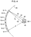
- Fig. 2B is a diagram showing an arc-shaped space light modulating apparatus 40.
- the flat space light modulating apparatus 26 of Fig. 2A in case of displaying a real image 30-1 when it is seen from a visual point 38 for the irradiation of a reference light 28, it is necessary to perform a diffraction at a large angle ⁇ 1 which is decided by a line 34 on the lower side of the real image 30-1 for a normal line 32.
- a phase distribution at a high spatial frequency must be displayed.
- a diffraction angle for the reference light 28 in case of displaying the real image 30-1 at the same position when it is seen from the visual point 38 can be set to a small angle ⁇ 2 for lines 44 and 46 which define both sides of the real image 30-1 from the normal line 42.
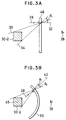
- a spatial frequency of an interference fringe as a phase distribution which is produced on the arc surface of the space light modulating apparatus 40 can be set to a low frequency. This point also shall apply to the display of a virtual image shown in each of Figs. 3A and 3B.
- Fig. 5 is a diagram showing liquid crystal display units which are used in the space light modulating units 12-1 to 12-7 in Fig. 1.
- a number of micro liquid crystal cells 58 are arranged in a matrix form on the display surface of the liquid crystal display unit 14.
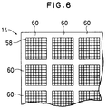
- Fig. 6 shows another embodiment of the liquid crystal display unit 14 which is used in the embodiment of Fig. 1.
- the embodiment is characterized in that a liquid crystal segment 60 in which a predetermined number of liquid crystal cells 58 are arranged in a matrix form is set to one unit and that a plurality of such liquid crystal segments 60 are two-dimensionally arranged in a matrix form.
- the liquid crystal display unit 14 can be easily manufactured as compared with the case where the liquid crystal cells 58 are arranged on the whole surface as shown in Fig. 5.
- Fig. 7 shows a structure of the liquid crystal display unit.
- the liquid crystal display unit 14 has a uniform transparent electrode 144 subsequent to a glass substrate 140 on the incident surface side. Branched transparent electrodes 146-1 to 146-n constructing one display segment are formed subsequent to a glass substrate 142 on the outgoing side. Orientation films 152 and 154 are provided through insulating layers 148 and 150 subsequent to the transparent electrodes 144 and 146-1 to 146-n. A liquid crystal 160 is provided between the orientation films 152 and 154.
- the liquid crystal display unit 14 is driven so that the voltage corresponding to the calculated phase information is applied to every liquid crystal cells which are decided by the divided electrodes 146-1 to 146-n.
- a refractive index of the liquid crystal cell for the transmitting direction of a reproduction light 162 is changed in accordance with the applied voltage.
- Fig. 8 shows a state of phase modulation with respect to three pixels of the liquid crystal display in Fig. 7 as an example.
- reproduction lights 162-1 to 162-3 comprising, for instance, plane waves having the same phase entered from the left side into pixels 166-1,166-2, and 166-3 which had been driven into different phase states, namely, to different refractive indices.
- phase deviations occur in lights 164-1 to 164-3 upon outgoing. It is ideally demanded that an arbitrary phase within a range of 0 to 2 ⁇ , namely, a range of a length corresponding to the wavelength as an optical distance can be expressed.
- a depth of liquid crystal is decided so as to satisfy conditions such that the product ⁇ n x d of the thickness d and a change ⁇ n in maximum refractive index which can be changed by the applied voltage is equal to a wavelength ⁇ of the reproduction light.
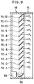
- Fig. 9 shows an embodiment of the illuminating units 16-1 to 16-2 provided on the back side of the space light modulating units 12-1 to 12-7 shown in Fig. 1.
- a laser light source 66 is built in on the lower side of the illuminating unit 16. It is desirable to use a small semiconductor laser as a laser light source 66.
- the semiconductor laser has a light emitting spectrum whose wavelength width is a few nm or less and can reconstruct a clear solid image. As a wavelength, an arbitrary wavelength can be used so long as it lies within a visible light range. It is necessary to consider a wavelength of light source which is used for reconstruction at the stage of calculating a phase distribution of a hologram.
- a semiconductor laser which emits the light of red whose wavelength is on the order of 600 nm, the light of green whose wavelength is on the order of 500 nm, or the light of blue whose wavelength is on the order to 400 nm.
- the light from the laser light source 66 is converted into the parallel light by a collimating mirror 68 and is irradiated upward.
- Twelve half mirrors 70-1 to 70-12 are arranged in the vertical direction of the illuminating unit 16 in the embodiment.
- the half mirrors 70-1 to 70-12 have transmission factors T1 to T12. Each half mirror reflects a part of the incident light.
- the reflected light enters the liquid crystal display unit 14 as a reproduction light. A part of the incident light also enters the next half mirror.
- a hologram is obtained as follows. One laser beam is divided into two beams. One laser beam is irradiated to an object, so that a laser beam (object light) is scattered by the object. A hologram is obtained by an interference of two light fluxes of the laser beam (object light) and another laser beam (reference light).
- a space light modulating apparatus such as a liquid crystal device or the like which can change an amplitude or phase of the light.
- a hologram By inputting the same wave front as the reference light to the hologram formed as mentioned above, a hologram can be reconstructed.
- the exposure intensity I H in the equation (1) only the third term of the right side contributes to the reconstruction of the object light. Therefore, when considering the third term of the right side, a transmission light T from the hologram is where, the first term of the right side in the equation (2) indicates that the wave front from the object was reproduced.
- the second term of the right side indicates a conjugate wave of the object light. From the above description of the principle, it will be understood that in order to obtain a phase distribution of the hologram, it is sufficient to calculate only the third term of the right side in the equation (1).
- Fig. 10 shows the principle by which a hologram is formed.
- a light intensity R can be ignored because an intensity of plane wave is not changed depending on the position.
- An object 62 to be displayed here is positioned so that an axial center line of a virtual cylindrical surface passes through, for example, the center of gravity.
- the coordinate system of a target space is set so that a proper reference position is set to an origin.
- the calculations of the equations (3) and (4) are executed with respect to the whole area of the hologram display surface 100.
- a position on the center axis of the space light modulating units 12-1 to 12-7 arranged along the cylindrical surface is set to a display center position of the solid image and, as shown in Fig. 10, a phase distribution which is expressed by each liquid crystal cell is calculated by the phase distribution calculating section 22 on a unit basis of each space light modulating unit 12-1.
- the space light modulating units 12-1 to 12-7 are driven by the display driving section 24 and the display driving according to the phase distribution is executed to each of the liquid crystal cells of the liquid crystal display units 14-1 to 14-7.
- the space light modulating units 12-1 to 12-7 are arranged along the arc in the horizontal direction and are flat in the vertical direction, so that the spatial frequency in the horizontal direction can be lowered.
- Fig. 1 shows a state in which the space light modulating units 12-1 to 12-7 are arranged in an arc shape in the horizontal direction, by falling down the display section 10 as a whole, the space light modulating units 12-1 to 12-7 can be arranged along the cylindrical surface in the vertical direction.
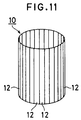
- Fig. 11 shows the second embodiment of a space light modulating apparatus of the invention and is characterized in that the same space light modulating units 12 as the space light modulating units 12-1 to 12-7 shown in Fig. 1 are arranged in a perfect arc shape along the cylindrical surface.
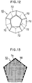
- Fig. 12 shows the third embodiment of the invention and is characterized in that the display section 10 of a regular dodecahedron is formed by arranging space light modulating units 72 each having a regular pentagon.
- Fig. 13 shows one of the space light modulating units 72 of the regular pentagon which are used in the space light modulating apparatus that is constructed by the regular dodecahedron of Fig. 12.
- a liquid crystal display units shown in Figs. 7 and 8 are used and the liquid crystal cells 58 are arranged in a matrix form in regions other than a non-display region 74 shown by a black area.
- Fig. 14 shows a modification of Fig. 12 and is characterized in that three space light modulating units 72 of the regular pentagon arranged on the lower side of the display section 10 which is constructed by the regular dodecahedron of Fig. 12 are removed, thereby forming a dome shape.
- Fig. 15 shows the fourth embodiment of a space light modulating apparatus of the invention and is characterized in that the display section 10 of a regular trisoctahedron is formed by arranging space light modulating units 76 of a regular triangle along a spherical surface.
- the space light modulating units 76 of a regular triangle which are used in the embodiment have an arrangement structure of the liquid crystal cells 58 shown in Fig. 16.
- Fig. 17 is characterized in that the five space light modulating units 76 of the regular triangle on the lower side with respect to the fourth embodiment of Fig. 15 are removed, thereby forming a dome shape.
- Fig. 18 shows the fifth embodiment of a space light modulating apparatus of the invention and is characterized in that the display section 10 as a polyhedron of the Fullerene type is formed by combining the space light modulating units 72 of the regular pentagon and space light modulating units 78 of a regular hexagon along a spherical surface.
- the space light modulating units 78 of the regular hexagon which are used in Fig. 18 have a matrix-like arrangement of the liquid crystal cells 58 shown in Fig. 19.
- Fig. 20 is characterized in that a dome shape is formed by removing the portion on the lower side of the display section 10 comprising polyhedrons of the Fullerene type of Fig. 18.
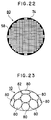
- Fig. 21 shows the fifth embodiment of a space light modulating apparatus of the invention and is characterized in that the display section 10 is formed by arranging circular space light modulating units 80 having a matrix arrangement of the liquid crystal sells 58 shown in Fig. 22 along a spherical surface.
- Fig. 23 is characterized in that a dome shape is formed by removing the lower half portion of Fig. 21.
- the spatial frequency can be lowered by reducing the diffraction angles in all of the directions including the horizontal and vertical direction.
- a size of the space light modulating apparatus in each of the foregoing embodiments is properly decided as necessary and is not limited.
- a stereoscopic display can be performed at a low spatial frequency. Even when a pixel density is small, a solid image can be displayed on a large screen. A clear solid image can be displayed because it is not so away from the visual point.
Landscapes
- Physics & Mathematics (AREA)
- General Physics & Mathematics (AREA)
- Chemical & Material Sciences (AREA)
- Crystallography & Structural Chemistry (AREA)
- Engineering & Computer Science (AREA)
- Theoretical Computer Science (AREA)
- Holo Graphy (AREA)
- Liquid Crystal (AREA)
Applications Claiming Priority (3)
| Application Number | Priority Date | Filing Date | Title |
|---|---|---|---|
| JP24899092 | 1992-09-18 | ||
| JP248990/92 | 1992-09-18 | ||
| JP4248990A JPH06102813A (ja) | 1992-09-18 | 1992-09-18 | 空間光変調装置および立体表示装置 |
Publications (3)
| Publication Number | Publication Date |
|---|---|
| EP0588509A2 true EP0588509A2 (fr) | 1994-03-23 |
| EP0588509A3 EP0588509A3 (en) | 1996-05-29 |
| EP0588509B1 EP0588509B1 (fr) | 2000-03-29 |
Family
ID=17186385
Family Applications (1)
| Application Number | Title | Priority Date | Filing Date |
|---|---|---|---|
| EP93306623A Expired - Lifetime EP0588509B1 (fr) | 1992-09-18 | 1993-08-20 | Appareil d'affichage stéréoscopique |
Country Status (5)
| Country | Link |
|---|---|
| US (1) | US5594559A (fr) |
| EP (1) | EP0588509B1 (fr) |
| JP (1) | JPH06102813A (fr) |
| CA (1) | CA2105118C (fr) |
| DE (1) | DE69328223T2 (fr) |
Cited By (6)
| Publication number | Priority date | Publication date | Assignee | Title |
|---|---|---|---|---|
| WO1996009864A1 (fr) * | 1994-09-27 | 1996-04-04 | Oellers E Hans | Scene |
| EP1331495A2 (fr) | 2002-01-23 | 2003-07-30 | Omron Corporation | Dispositif source de lumière de surface, plaque diffusante et dispositif d'affichage à cristaux liquides |
| EP1220189A3 (fr) * | 2000-12-26 | 2004-07-14 | Ngk Insulators, Ltd. | Dispositif d'affichage |
| EP1650729A3 (fr) * | 2004-10-07 | 2007-11-28 | Barco, naamloze vennootschap. | Dispositif d'affichage amélioré et support correspondant, modules d'affichage à émission lumineuse et empaquetage pour tels modules d'affichage |
| EP1528442A4 (fr) * | 2002-08-05 | 2008-04-02 | Pioneer Corp | Modulateur optique spatial |
| CN113903254A (zh) * | 2020-10-12 | 2022-01-07 | 友达光电股份有限公司 | 显示元件以及显示装置 |
Families Citing this family (15)
| Publication number | Priority date | Publication date | Assignee | Title |
|---|---|---|---|---|
| US6195184B1 (en) | 1999-06-19 | 2001-02-27 | The United States Of America As Represented By The Administrator Of The National Aeronautics And Space Administration | High-resolution large-field-of-view three-dimensional hologram display system and method thereof |
| US10083542B1 (en) * | 1999-10-21 | 2018-09-25 | International Business Machines Corporation | Method and system to compare and search polyhedral shape |
| JP3513562B2 (ja) * | 2000-04-20 | 2004-03-31 | インターナショナル・ビジネス・マシーンズ・コーポレーション | 形状解析システム、3次元形状モデルの差分検出システム、類似形状検索システム、形状解析方法及び記憶媒体 |
| GB2379351A (en) * | 2001-09-04 | 2003-03-05 | Holographic Imaging Llc | Illuminating a computer generated hologram |
| US6927886B2 (en) * | 2002-08-02 | 2005-08-09 | Massachusetts Institute Of Technology | Reconfigurable image surface holograms |
| KR101908033B1 (ko) | 2008-07-10 | 2018-12-10 | 리얼 뷰 이미징 리미티드 | 광시야각 디스플레이들 및 사용자 인터페이스들 |
| CN102013222A (zh) * | 2010-10-29 | 2011-04-13 | 鸿富锦精密工业(深圳)有限公司 | 球状显示屏 |
| WO2012095703A1 (fr) * | 2011-01-14 | 2012-07-19 | Onural, Levent | Appareil et procédés pour un affichage holographique |
| KR102250189B1 (ko) * | 2014-07-29 | 2021-05-10 | 삼성전자주식회사 | 홀로그래피 재생 장치 및 재생 방법 |
| WO2016076749A1 (fr) * | 2014-11-14 | 2016-05-19 | Михаил Алексеевич ФИЛИМОНОВ | Dispositif pour affichage visuel des informations |
| CN206833886U (zh) * | 2017-04-11 | 2018-01-02 | 河北思安科技有限公司 | 激光智能投射多媒体广告平台 |
| SG11202100408XA (en) | 2018-07-25 | 2021-02-25 | Light Field Lab Inc | Light field display system based amusement park attraction |
| CN110442006B (zh) | 2019-06-28 | 2021-08-27 | 京东方科技集团股份有限公司 | 全息再现装置、全息再现系统和全息显示系统 |
| US11317039B1 (en) * | 2021-01-06 | 2022-04-26 | Visera Technologies Company Limited | Image-sensing device |
| KR20240085348A (ko) * | 2022-12-07 | 2024-06-17 | 삼성디스플레이 주식회사 | 표시 장치 |
Family Cites Families (11)
| Publication number | Priority date | Publication date | Assignee | Title |
|---|---|---|---|---|
| US3601466A (en) * | 1968-06-21 | 1971-08-24 | Nippon Kogaku Kk | Method for detecting an aberration-compensated image |
| US3591252A (en) * | 1968-10-21 | 1971-07-06 | Texas Instruments Inc | Large array synthesizing |
| DE2229381A1 (de) * | 1972-06-16 | 1974-01-03 | Agfa Gevaert Ag | Verfahren und vorrichtung zur aufzeichnung eines in einem hologramm gespeicherten objektwellenfeldes |
| JPS5786815A (en) * | 1980-11-19 | 1982-05-31 | Yokogawa Hokushin Electric Corp | Photoscanner |
| DE3140418A1 (de) * | 1981-10-12 | 1983-05-05 | Stadelmayr, Hans-Günther, 8000 München | Bild- und raumbild-(hologramm)-produktions- transmissions- und reproduktions-system fuer grosse ausdehnung (extensitaet) bei gleichzeitiger hoher aufloesung (intensitaet) |
| US4863225A (en) * | 1986-03-26 | 1989-09-05 | Gec Avionics Limited | Reflection holograms formed by scanning |
| GB2209422B (en) * | 1987-09-03 | 1991-05-29 | Emi Plc Thorn | Displays |
| FR2633069B1 (fr) * | 1988-06-20 | 1993-12-31 | Garcon Thierry | Procede de realisation d'un hologramme de transfert a grand champ de vision sur son imagerie reelle orthoscopique et hologramme ainsi obtenu |
| US5111313A (en) * | 1989-08-10 | 1992-05-05 | Shires Mark R | Real-time electronically modulated cylindrical holographic autostereoscope |
| JP2785427B2 (ja) * | 1990-03-26 | 1998-08-13 | 松下電器産業株式会社 | 計算機ホログラムの作成方法 |
| US5198914A (en) * | 1991-11-26 | 1993-03-30 | Hughes Aircraft Company | Automatic constant wavelength holographic exposure system |
-
1992
- 1992-09-18 JP JP4248990A patent/JPH06102813A/ja active Pending
-
1993
- 1993-08-20 DE DE69328223T patent/DE69328223T2/de not_active Expired - Fee Related
- 1993-08-20 EP EP93306623A patent/EP0588509B1/fr not_active Expired - Lifetime
- 1993-08-30 CA CA002105118A patent/CA2105118C/fr not_active Expired - Fee Related
-
1996
- 1996-04-10 US US08/632,346 patent/US5594559A/en not_active Expired - Lifetime
Cited By (7)
| Publication number | Priority date | Publication date | Assignee | Title |
|---|---|---|---|---|
| WO1996009864A1 (fr) * | 1994-09-27 | 1996-04-04 | Oellers E Hans | Scene |
| EP1220189A3 (fr) * | 2000-12-26 | 2004-07-14 | Ngk Insulators, Ltd. | Dispositif d'affichage |
| EP1331495A2 (fr) | 2002-01-23 | 2003-07-30 | Omron Corporation | Dispositif source de lumière de surface, plaque diffusante et dispositif d'affichage à cristaux liquides |
| EP1528442A4 (fr) * | 2002-08-05 | 2008-04-02 | Pioneer Corp | Modulateur optique spatial |
| EP1650729A3 (fr) * | 2004-10-07 | 2007-11-28 | Barco, naamloze vennootschap. | Dispositif d'affichage amélioré et support correspondant, modules d'affichage à émission lumineuse et empaquetage pour tels modules d'affichage |
| CN113903254A (zh) * | 2020-10-12 | 2022-01-07 | 友达光电股份有限公司 | 显示元件以及显示装置 |
| CN113903254B (zh) * | 2020-10-12 | 2023-11-14 | 友达光电股份有限公司 | 显示元件以及显示装置 |
Also Published As
| Publication number | Publication date |
|---|---|
| CA2105118A1 (fr) | 1994-03-19 |
| DE69328223T2 (de) | 2000-09-07 |
| EP0588509A3 (en) | 1996-05-29 |
| CA2105118C (fr) | 1999-01-05 |
| JPH06102813A (ja) | 1994-04-15 |
| US5594559A (en) | 1997-01-14 |
| DE69328223D1 (de) | 2000-05-04 |
| EP0588509B1 (fr) | 2000-03-29 |
Similar Documents
| Publication | Publication Date | Title |
|---|---|---|
| EP0588509A2 (fr) | Appareil d'affichage stéréoscopique | |
| US7414769B2 (en) | Reconfigurable spatial light modulators | |
| CA2103950C (fr) | Methode d'affichage stereoscopique d'un hologramme, methode de formation et dispositif d'affichage stereoscopique | |
| EP0590913B1 (fr) | Méthode et dispositif d'affichage stéréoscopique | |
| CN100578392C (zh) | 三维场景的全息再现装置 | |
| US6473209B1 (en) | Apparatus for producing a three-dimensional image | |
| CN102063046B (zh) | 一种应用显示装置生成物体的全息再现的方法 | |
| US20050122549A1 (en) | Computer assisted hologram forming method and apparatus | |
| CN108803295B (zh) | 大视场全息图的制作方法、显示系统及点阵光源 | |
| JP2009533721A (ja) | 角度スライスの本当の3dディスプレイに係るシステム及び方法 | |
| WO2005099386A2 (fr) | Projecteur holographique | |
| JPH11513814A (ja) | 液晶ディスプレイ内に組み込んだ、ホログラフ高コントラスト視野スクリーン | |
| US10816932B2 (en) | Apparatus for displaying a hologram | |
| Toda et al. | Three-dimensional (3D) video system using grating image | |
| JPH1068906A (ja) | ホログラフィック表示装置 | |
| JP3338479B2 (ja) | ホログラムの作成および立体表示方法並びに立体表示装置 | |
| KR100466622B1 (ko) | 광굴절 기록매질 제작 장치 및 그 방법과 그를 이용한3차원 홀로그래픽 디스플레이 장치 및 그 방법 | |
| EP0586098B1 (fr) | Modulateur spatial de lumière | |
| EP3129836B1 (fr) | Caméra vidéo holographique à grand angle de vue et afficheur utilisant une lame de phase | |
| JP3292516B2 (ja) | 空間光変調装置および立体表示装置 | |
| Jones et al. | Liquid crystal display based implementation of a real-time ICVision holographic stereogram display | |
| CN119846929A (zh) | 一种大视场全息平板显示装置 | |
| JP2838163B2 (ja) | 動的三次元画像の表示方法 | |
| JPH10332917A (ja) | 回折素子パネル及びそれから構成される三次元画像表示装置 |
Legal Events
| Date | Code | Title | Description |
|---|---|---|---|
| PUAI | Public reference made under article 153(3) epc to a published international application that has entered the european phase |
Free format text: ORIGINAL CODE: 0009012 |
|
| AK | Designated contracting states |
Kind code of ref document: A2 Designated state(s): DE FR GB |
|
| PUAL | Search report despatched |
Free format text: ORIGINAL CODE: 0009013 |
|
| AK | Designated contracting states |
Kind code of ref document: A3 Designated state(s): DE FR GB |
|
| 17P | Request for examination filed |
Effective date: 19961121 |
|
| 17Q | First examination report despatched |
Effective date: 19970103 |
|
| GRAG | Despatch of communication of intention to grant |
Free format text: ORIGINAL CODE: EPIDOS AGRA |
|
| GRAG | Despatch of communication of intention to grant |
Free format text: ORIGINAL CODE: EPIDOS AGRA |
|
| GRAH | Despatch of communication of intention to grant a patent |
Free format text: ORIGINAL CODE: EPIDOS IGRA |
|
| GRAH | Despatch of communication of intention to grant a patent |
Free format text: ORIGINAL CODE: EPIDOS IGRA |
|
| GRAA | (expected) grant |
Free format text: ORIGINAL CODE: 0009210 |
|
| AK | Designated contracting states |
Kind code of ref document: B1 Designated state(s): DE FR GB |
|
| REF | Corresponds to: |
Ref document number: 69328223 Country of ref document: DE Date of ref document: 20000504 |
|
| ET | Fr: translation filed | ||
| PLBE | No opposition filed within time limit |
Free format text: ORIGINAL CODE: 0009261 |
|
| STAA | Information on the status of an ep patent application or granted ep patent |
Free format text: STATUS: NO OPPOSITION FILED WITHIN TIME LIMIT |
|
| 26N | No opposition filed | ||
| REG | Reference to a national code |
Ref country code: GB Ref legal event code: IF02 |
|
| PGFP | Annual fee paid to national office [announced via postgrant information from national office to epo] |
Ref country code: FR Payment date: 20060808 Year of fee payment: 14 |
|
| PGFP | Annual fee paid to national office [announced via postgrant information from national office to epo] |
Ref country code: GB Payment date: 20060816 Year of fee payment: 14 |
|
| PGFP | Annual fee paid to national office [announced via postgrant information from national office to epo] |
Ref country code: DE Payment date: 20060817 Year of fee payment: 14 |
|
| GBPC | Gb: european patent ceased through non-payment of renewal fee |
Effective date: 20070820 |
|
| REG | Reference to a national code |
Ref country code: FR Ref legal event code: ST Effective date: 20080430 |
|
| PG25 | Lapsed in a contracting state [announced via postgrant information from national office to epo] |
Ref country code: DE Free format text: LAPSE BECAUSE OF NON-PAYMENT OF DUE FEES Effective date: 20080301 |
|
| PG25 | Lapsed in a contracting state [announced via postgrant information from national office to epo] |
Ref country code: FR Free format text: LAPSE BECAUSE OF NON-PAYMENT OF DUE FEES Effective date: 20070831 |
|
| PG25 | Lapsed in a contracting state [announced via postgrant information from national office to epo] |
Ref country code: GB Free format text: LAPSE BECAUSE OF NON-PAYMENT OF DUE FEES Effective date: 20070820 |