EP0588626B2 - Dispositif de mesure de débit d'air - Google Patents
Dispositif de mesure de débit d'air Download PDFInfo
- Publication number
- EP0588626B2 EP0588626B2 EP93307289A EP93307289A EP0588626B2 EP 0588626 B2 EP0588626 B2 EP 0588626B2 EP 93307289 A EP93307289 A EP 93307289A EP 93307289 A EP93307289 A EP 93307289A EP 0588626 B2 EP0588626 B2 EP 0588626B2
- Authority
- EP
- European Patent Office
- Prior art keywords
- air
- air passage
- flow rate
- sub
- rate measuring
- Prior art date
- Legal status (The legal status is an assumption and is not a legal conclusion. Google has not performed a legal analysis and makes no representation as to the accuracy of the status listed.)
- Expired - Lifetime
Links
Images


Classifications
-
- G—PHYSICS
- G01—MEASURING; TESTING
- G01F—MEASURING VOLUME, VOLUME FLOW, MASS FLOW OR LIQUID LEVEL; METERING BY VOLUME
- G01F5/00—Measuring a proportion of the volume flow
-
- G—PHYSICS
- G01—MEASURING; TESTING
- G01M—TESTING STATIC OR DYNAMIC BALANCE OF MACHINES OR STRUCTURES; TESTING OF STRUCTURES OR APPARATUS, NOT OTHERWISE PROVIDED FOR
- G01M11/00—Testing of optical apparatus; Testing structures by optical methods not otherwise provided for
-
- G—PHYSICS
- G01—MEASURING; TESTING
- G01F—MEASURING VOLUME, VOLUME FLOW, MASS FLOW OR LIQUID LEVEL; METERING BY VOLUME
- G01F1/00—Measuring the volume flow or mass flow of fluid or fluent solid material wherein the fluid passes through a meter in a continuous flow
- G01F1/68—Measuring the volume flow or mass flow of fluid or fluent solid material wherein the fluid passes through a meter in a continuous flow by using thermal effects
- G01F1/684—Structural arrangements; Mounting of elements, e.g. in relation to fluid flow
- G01F1/6842—Structural arrangements; Mounting of elements, e.g. in relation to fluid flow with means for influencing the fluid flow
Definitions
- the present invention relates to an air flow rate measuring device of the type which employs a heat-generating resistor and, more particularly, to an air flow rate measuring device of the type described, suitable for use In measuring intake air flow rate in an automotive engine to obtain air flow rate information to be used In the control of fuel injection performed in such an engine.
- a conventional air flow rate measuring device of the type using a heat-generating resistor is disclosed in, for example, Japanese Patent Unexamined Publication No. 2-232524.
- This conventional device includes a sub-air passage having a recessed inlet and orthogonally bent at a portion downstream of a flow rate measuring portion so as to open In a joining outlet provided in the vicinity of the wall of a main air passage, thereby diminishing output variation in the air flow rate measuring device caused by an offset of flow of the air occurring in the region upstream of the air flow rate measuring device.
- the above-described arrangement has not been considered to eliminate influence of an air cleaner or other component which would cause such an offset of the air flow that the velocity is high in the region between the region of the sub-air passage upstream of the flow rate measuring portion and the center of the main air passage.
- the above-mentioned known arrangement cannot satisfactorily reduce error or deviation of the measuring output to the plus side which is caused when the above-mentioned offset of the air flow exists.
- EP-A-0386966 and EP-A-0313089 both disclose hot wire-type air flow meters in which there is a main air flow passage and an auxiliary airflow passage disposed within the main air flow passage.
- the Auxiliary air flow passage has an inlet residing in the longitudinal plane of the main air passage but in which the outlet of the auxiliary air passage is disposed to displace air therefrom generally orthogonally to the longitudinal direction of the main air flow passage.
- GB-A-2065898 discloses an air flow rate measuring device utilising a Venturi tube. Because the Venturi tube gradually reduces in diameter, so the air flow is narrowed with little resistance so that the pressure at the region upstream of an auxiliary air passage remains relatively unchanged.
- EP-A-458 081 discloses a hot-wine type air flow meter with a sub air passage containing the metering sensors in an egg shaped member mounted in the main passage.
- US-3 314 290 discloses an impact restriction shunt flow meter in one example of which a restriction is present in the main air passage, positioned upstream of the outlet of a bypass passage, which is partially external of the main air passage.
- the known air flow rate measuring device Is not designed for providing sufficiently high measuring accuracy to a variety of arrangement of the conduit upstream of the air flow rate measuring device and a variety of configurations of air cleaner, and is adapted only to a specific configuration of the air cleaner.
- the known air flow rate measuring device can provide measuring accuracy only when it is combined with specific configurations of the conduit upstream of the measuring device.
- no air flow rate measuring device has been proposed which would provide sufficiently high measuring accuracy adapting to various designs of air cleaner and air duct of automotive engines, through elimination of influence of offset of the air flow, in particular such an offset that the velocity is highest In the central portion of the main air passage as in the case where a straight duct is adopted.
- an object of the present invention is to provide an air flow rate measuring device which can measure air flow rate with a high degree of accuracy, adapting to a variety of forms of the upstream structure, i.e., forms of the air cleaner and duct upstream of the air flow rate measuring device, in particular such a configuration of the upstream structure that develops highest flow velocity in the central portion of the main air passage.
- an air flow rate measuring device as claimed in claim 1.
- the invention also provides a fuel control system for an Internal combustion engine, comprising: an air flow rate measuring device as defined in claim 1; fuel injection means for injecting a fuel at a controlled rate and timing; and a control unit for receiving a signal from the air flow rate measuring device Indicative of the flow rate of intake air and for computing the injection rate and timing based on the signal and delivering the result of the computation to the fuel injection means.
- Such flow velocity distribution patterns are broadly sorted into three types: a pattern in which flow velocity is substantially uniform over the entire area of the cross-section of the air passage; a stratified or laminate pattern which is caused by, for example, a bend of the duct such that, velocity is higher in the radially outer region of the curvature than in the inner region; and a curve-shaped pattern which is formed by, for example, the presence of a long straight duct such that the flow velocity is highest In the core portion of. the passage and lowest in the peripheral region near the wall defining the passage.
- the inlet opening of the sub-air passage is so positioned as to include the axis of the main air passage so that the air is introduced into the flow rate measuring portion preferentially from the central portion of the main air passage, thus preventing the measuring output from largely shifted or deviated to the minus side, i.e., to the smaller side.
- the present invention In its another aspect proposes to provide an arrangement in which a smaller pressure drop occurs at the joining outlets of the sub-air passage when the velocity of the principal flow of air is low in the region immediately upstream of the joining outlets.
- the pattern of flow velocity distribution varies widely according to factors such as configurations of the air cleaner and duct. In order to achieve sufficiently high degree of accuracy of measurement despite such a variety of distribution patterns, it is necessary to locally adjust the degrees of influence of flow rate variations at different regions.
- the degree of influence of the flow velocity of the air in the main air passage upstream of the joining outlet is controllable by-varying the height of protrusions provided on both side faces of the bridge.
- Fig. 1 is a sectional view of an air flow rate measuring device
- Fig. 2 is an end view as viewed, from the upstream side (left side as viewed on Fig. 1)
- Fig. 3 is a sectional view taken along the line III-III of Fig. 1.
- the air flow rate measuring device has a body 3 in which is defined a main air passage 5.
- a bridge 2 is formed in the body 3 so as to bridge opposing ends of the wall of the body 3 across the main air passage 5.
- a sub-air passage 4 formed in the bridge 2 is provided with a heat-generating resistor 7 for detecting the air flow rate and a heat-sensitive resistor 8 for detecting the temperature of the intake air.
- the heat-generating resistor and the heat-sensitive resistor are electrically connected to a module 9 incorporating a driving circuit, through a support member 10.
- the sub-air passage 4 has an axial portion which has a sub-air passage inlet 4a and extends in parallel with the main passage 5.
- the axial passage is orthogonally bent at a portion thereof downstream of the flow rate measuring portion where the heat-generating resistor is disposed, thus forming a diametrical portion which extends to open in a joining outlet 4b.
- the main air passage 5, the bridge 2 and the sub-air passage 4 are integrally formed in the body 3.
- the axis of the axial portion of the sub-air passage 4 is deviated from the axis of the main air passage 5.
- the sub-air passage inlet 4a is extended to include the central portion of the main air passage 5 and has a tapered bottom so that the air falling within the area of the inlet 4a is introduced into the sub-air passage to reach the flow rate measuring portion.
- the portion of air flow In the central region of the main air passage 5, the velocity of which substantially approximates the velocity of the uniform flow of air, is introduced even when such a non-uniform flow distribution or offset of air flow exists that exhibits low flow velocity at the upstream side of the axial portion of the sub-air passage 4.
- This arrangement reduces deviation of the output of the air flow rate measuring device from the value which would be obtained if uniform flow of air is formed without any offset in the main air passage 5.
- protrusions 1 are formed on both sides of the bridge 2 upstream of the joining outlet 4b of the sub-air passage 4 where the air from the sub-air passage 4 joins the air flowing through the main air passage 5.
- the air flowing in the main air passage 5 along both side faces of the bridge 2 collides with the protrusion 1, so that, by increasing the velocity of the principal air flow, separation or burble of air flowing from the side faces of the bridge 2 is caused the vicinity of the region where the joining outlet 4b exists, with the result that the pressure of air in the main air passage 5 is reduced in this region so that the air which has been introduced into the sub-air passage 4 can be discharged through the joining outlet 4b without being interfered by the flow of the air-in the main air passage 5.
- the output of the air flow rate measuring device tends to be deviated to the greater side because the sub-air inlet 4a is so shaped as to take up the portion of the air flow in the central region of the main passage 5.
- Such deviation of the measuring output is suppressed in the described embodiment for the following reason. Namely, when such a curve-shaped flow velocity distribution exists, the flow velocity is comparatively small in the region around the joining outlet 4b which is disposed in the vicinity of the wall of the main air passage, and thus, the foregoing separation of the air flow is small.
- the pressure reduction appearing in the region where the joining outlet 4b exists is smaller than the case where the flow velocity distribution is uniform, so that the rate of flow of the air through the sub-air passage 4 is reduced correspondingly, thus suppressing the above-described deviation of the measuring output.
- the bridge 2 having the sub-air passage 4 formed therein, the main air passage 5 and the mount for the circuit module can be formed integrally as a body 3 by plastic molding or by casting.
- the diametrical portion of the sub-air passage 4 is obtained by forming a groove in the downstream side of the bridge 2 by molding or casting, and attaching a cover 6 to the downstream or rear ends of the side walls of the groove.
- the cover 6 extends to join the wall of the body 3 while the side walls of the groove are omitted at their ends adjacent the wall of the body so as to provide a pair of openings which open in the left and right sides of the bridge 2 thus forming the joining outlet 4b.
- the vortices generated as a result of the burble of the air flow in the sub-air passage joining outlet 4b are largely influenced by the configuration of the upstream edge of each tabular protrusion 1. Namely, a greater burble effect is obtained even when the height of the protrusion is small, provided that the upstream edge of the tabular protrusion is not rounded.
- the integral structure is formed by a split mold which has a parting plane coinciding with the plane of the upstream flat surfaces of the tabular protrusions 1,.
- a thick-walled portion can never be eliminated by vertical pattern drawing.
- a vacant portion 11 opening in the wall of the body 3 is formed so as to prevent any deformation which otherwise may be caused by shrinkage of the thick-walled portion.
- Figs. 4 to 6 show a device in which an upwardly facing flat surface 2a is provided upstream of the joining outlet of the sub-air passage so as to generate burble vortices.
- Fig. 4 is a sectional view of this device
- Fig. 5 is an end view as viewed from the upstream side (left side as viewed on Fig. 4)
- Fig. 6 is a sectional view taken along the line VI-VI of Fig. 4.
- a main air passage 5 and a sub-air passage 4 are formed in a body 3 of the air flow rate measuring device.
- a flow rate measuring portion including a heat-generating resistor 7 and a temperature-sensitive resistor 8 is provided in the sub-air passage 4.
- an inlet 4a of the sub-air passage is provided near the central region of the main air passage 5 and the sub-air passage 4 branches into a plurality of branches downstream of the flow rate measuring portion so as to provide a plurality of merging outlets 4b.
- the inlet 4a of the sub-air passage is disposed in the central region of the main air passage 5, it is possible to reduce the deviation of the measuring output to minus side when a stratified flow pattern is generated in the region upstream of the air flow rate measuring device.
- the deviation of the measuring output to the plus side is increased when the air flow in the main air passage exhibits such a curve-shaped flow velocity distribution pattern that the highest velocity appears in the central region of the main air passage.
- the sub-air passage 4 is substantially orthogonally bent at a portion thereof downstream of the flow rate measuring portion and the joining outlets 4b of the sub-air passage 4 are disposed in the vicinity of the wall of the main air passage 5, with the above-mentioned flat surface 2a disposed upstream of the joining outlets 4 so as to extend normally to the principal flow of the air inside the main air passage 5.
- the flow velocity is high in the region upstream of the inlet 4a of the sub-air passage 4 and low in the regions upstream of the joining outlets 4b, tending to reduce the rate of flow of the air through the sub-air passage 4, thereby suppressing the deviation of the measuring output to the plus side which otherwise may be caused by the high velocity of the air flowing into the sub-air passage 4.
- Fig. 7 is a sectional view of a device in which the circuit module 9 is integrated with the bridge 2 which is Inserted into a hole formed in the wall of the body 3 so as to project into the main air passage 5.
- Fig. 8 is an end view of this embodiment as viewed from the upstream side
- Fig. 9 is a sectional view taken along the line IX-IX of Fig. 7.
- the sub-air passage 4 has two inlets 4a one of which opens in a region which contains the center of the main air passage 5. Conduits leading from these inlets 4a join each other at a portion upstream of the heat-generating resistor 7 so as to form an axial portion of the sub-air passage 4, which is then bent orthogonally to form diametrical portion of the sub-air passage 4.
- the body 3 has a simple cylindrical form, with the opening for receiving the bridge 2 and a seat for mounting the circuit module.
- protrusions 1, 1 having a triangular cross-section are provided on both lateral sides of the bridge 2 at positions Immediately upstream of the joining outlets 4b so as to produce more stable burble vortices zones than the embodiments explained in connection with Figs. 1 and 3.
- These protrusions 1, 1 produce almost the same effect against any offset or uneven flow velocity distribution as those produced by the protrusions of Fig. 3 and the flat surface of Fig. 6.
- the bridge 2 can be formed by casting or molding by using a split mold having a parting plane which coincides with the downstream faces of the triangular protrusions.
- the triangular visor-shaped protrusion 1 can be shaped to have an apex of an acute angle and, hence, a reduced height.
- Figs. 10 to 12 show the device shown in Fig. 1, having different arrangements for generating burble vortices. These modifications are typical three examples of the configurations of the above-mentioned arrangement other than those shown in Figs. 3, 6 and 9, and are shown in section corresponding to the section taken along the line III-III of Fig. 1.
- the bridge has the same configuration as those of known air flow rate measuring devices.
- a pair of rod-shaped obstacles 2b are provided in the regions upstream of the joining outlets 4b in order to impede the principal flow of the air so as to generate burble vortices.
- the surfaces of the bridge themselves do not cause burble of the flow of air but the rod-shaped obstacles 2b which are disposed in the vicinity of the bridge causes impediment to the principal flow of the air so that burble vortices are generated in the region Immediately downstream of these rod-shaped obstacles 2b and immediately upstream of the outlets of the sub-air passage, thus producing the same effect as those produced by the protrusions or flat surface in the preceding embodiments.
- the obstacles having circular cross-section are employed in this modification, obstacles having other cross-sections such as rectangular or triangular sections may be used in order to enhance the effect of producing burble vortices.
- each of the side face has an upstream slant surface which extends over a substantial length from one of the upstream end edges of the bridge 2 so as to converge towards the upstream end of the body of the flow rate measuring device, and a downstream end surface also is tapered to converge towards the downstream side.
- the effect to produce the burble vortices is not so strong because the side faces have gently slanted upstream and downstream surfaces.
- This arrangement offers an advantage in that the velocity of the upstream air at which the burble takes place is varied adjustable by suitably selecting the tapers of the slant surfaces.
- the bridge 2 is positioned at a level below the inlet 4a of the sub-air passage 4 in the region immediately upstream of the outlets 4b of the sub-air passage 4.
- the bridge 2 is wedge-shaped such that its both side surfaces diverge towards the downstream end, rather than being provided with protrusions on Its both lateral side surfaces.
- the flow of air colliding with the bridge is forced to change its flowing direction so that burble vortices are generated in the regions downstream of both side surfaces of the bridge.
- the modification shown in Fig. 12 can be considered as being a compromise of the device in which the bridge has a flat upstream end surface normal to the flow of the air and the embodiments in which protrusions are formed on both lateral side surfaces of the bridge.
- Fig. 13 is a sectional view of this device
- Fig. 14 is an end view as viewed from the upstream side
- Fig. 15 is a sectional view taken along the line XV-XV of Fig. 13.
- This air flow rate measuring device has a body 3 which defines a main air passage 5 and a sub-air passage 4 formed therein.
- the body 3 also has a structure for mounting and fixing a circuit module 9 thereon.
- a flow rate measuring element 7 is disposed to project into the sub-air passage 4 and is electrically connected to an electrical circuit in the circuit module 9.
- an air temperature sensing element 8 also is fixed to project into the sub-air passage 4 as in the case of the flow rate measuring element 7.
- the sub-air passage 4 is orthogonally bent at a portion downstream of these elements 7, 8 so as to form a diametrically extending portion perpendicular to the direction of the principal flow of the air in the main air passage.
- the diametrically extending portion is formed by forming a downwardly facing diametrical groove and closing the groove by a cover 6.
- the inlet 4a of the sub-air passage 4 also has the form of a groove which extends in the diametrical direction of the main air passage 5, with the bottom of the groove tapered upwardly rearward as viewed in Fig. 13. More specifically, the inlet surface of the sub-air passage 4 is stepped to have two portions; namely, a first upper step which is remoter from the flow rate measuring portion and closer to an upstream flow rectifying grating 12 and a second lower step closer to and axially aligned with the flow rate measuring portion and remoter from the grating 12, and the steps are connected by a tapered surface.
- the air which has just been discharged through the flow rectifying grating 12 has a large inertia acting in the direction of the principal flow of air, i.e., in the direction of axis of the main passage 5. Consequently, the first upper step of the inlet portion of the sub-air passage 4, which is closer to the grating 12, receives air having large inertia in the axial direction.
- protrusions 1 are provided on the lateral side surfaces of the bridge upstream of the joining outlet 4b of the sub-air passage to enable adjustment of the rate of introduction of the air into the sub-air passage 4 due to the velocity of air flow upstream of the outlet.
- the protrusion 1 also is stepped to have two portions of different heights to enable adjustment of the influence of the air flow velocity upstream of the outlet of the sub-air passage.
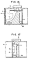
- Fig. 16 shows a flow rate measuring device in which, the inlet 4a of the sub-air passage is stepped according to the diametrical distance from the flow rate measuring portion so as to provide a local selectivity or preference of introduction of the air into the sub-air passage 4.
- the configuration of the inlet 4a of the sub-air passage 4 as viewed in section shown in Fig. 14 is different from that of the embodiment shown in Fig. 13.
- the inlet surface of the sub-air passage is so configured that one end portion of the inlet which is remotest from the flow rate measuring portion is positioned most upstream, i.e., closest to the flow rectifying grating 12, and the other end portion of the inlet which is closest to and axially aligned with the flow rate measuring portion is positioned downstream of the first-mentioned end of the inlet.
- Intermediate portion of the inlet between the above-mentioned two end portions is concave so as to be farthest from the grating 12, i.e., further to the downstream side beyond the position of the above-mentioned the other end portion of the inlet.
- air is less liable to be trapped at the intermediate portion of the inlet of the sub-air passage; namely, air is preferentially trapped and introduced into the flow rate measuring portion through the above-mentioned two end portions of the inlet.
- introduction of air into the sub-air passage is suppressed in the region around the axis of the main air passage where the flow velocity is liable to fluctuate largely when offset or unevenness flow pattern of the air occurs, whereas introduction of air is promoted at both end portions of the inlet. Consequently, the air is introduced at a rate which approximates the mean of the flow rate of air at these two end portions of the inlet, thus diminishing error in the measurement output which otherwise may occur due to offset or unevenness of the flow pattern of the air.
- the described devices can be produced without any rise in the production cost, because the inlet of the sub-air passage having the described configuration can easily be formed integrally with the body 3 by casting or plastic molding.
- the sub-air passage 4 can be bent orthogonally and the outlets of the sub-air passage can be formed to open in both lateral directions, so that the flow rate measuring device can produce a measuring output without any error caused by pulsation of the air flow and can be used stably for a long time against secular change which are caused by backfire from the engine or contamination.
- Fig. 17 shows a flow rate measuring device.
- the main passage 5 is constructed as part of the intake system of an engine, and the sub-air passage 4 which is integrated with the circuit module 9 is inserted into the intake system, thus completing a structure which functions as a flow rate measuring device.
- a portion of the intake system, which forms the main air passage 5, is provided with a flow rectifying grating 12.
- the wall defining the main air passage 5 is provided at a portion thereof downstream from the grating 12 with an opening through which the assembly having the sub-air passage 4 is inserted into the intake system.
- the wall also is provided with a seat structure for mounting and fixing the circuit module 9 thereon.
- the assembly having the sub-air passage 4 and the circuit module 9 integrated therewith is inserted into the intake passage through the above-mentioned opening and is fixed as the circuit module 9 is seated on and fixed to the above-mentioned seating structure.
- This embodiment also can have a stepped inlet surface 4a of the sub-air passage 4 and orthogonal bend of the sub-air passage at a portion downstream from the flow rate measuring portion.
- Fig. 18 is a sectional view of a device which has a greater area of the inlet through which the air is introduced into the flow rate measuring portion than the embodiments described hereinbefore, while Fig. 19 is an end view of this device as viewed from the upstream side.
- this has a main air passage 5 and a sub-air passage 4 which are integrally defined in a body 3.
- the flow rate measuring portion in the sub-air passage 4 including a flow rate measuring element 7 electrically connected to a circuit module 7, Is disposed on the axis of the main air passage 5.
- the inlet portion of the sub-air passage 4 has four slant grooves which extend radially so as to diverge from the flow rate measuring portion towards the upstream end, and the inlet surface 4a is configured to have two steps for each of these grooves: namely, an upper step which is on the radially outer upstream end of each groove and a lower step which is on the radially inner downstream end closer to the core region where the flow rate measuring portion is located.
- an upper step which is on the radially outer upstream end of each groove
- a lower step which is on the radially inner downstream end closer to the core region where the flow rate measuring portion is located.
- this device is devoid of any flow rectifying grating, error in the measuring output caused by flow offset or uneven flow velocity distribution can be further diminished when a flow rectifying grating of mesh or honey-comb type is employed also in this embodiment.
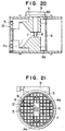
- Fig. 20 is a sectional view of a flow rate measuring device, while Fig. 21 is an end view as viewed from the upstream side of the embodiment.
- the inlet portion 4a of the sub-air passage is configured to have grooves which, when viewed from the upstream side, extends in a diametrical direction of the main air passage, with a bottom which converges towards the downstream flow rate measuring portion.
- the inlet surface is so stepped that the radially central region of the surface around the axis of the main air passage 5 Is projected in the upstream direction towards the flow rectifying grating 12.
- the flow rectifying grating 12 has a central mask portion which is located on the axis of the main air passage 5 immediately upstream of the central projected portion of the inlet surface of the sub-air passage and which does not permit to air to pass therethrough.
- the inlet surface of the sub-air passage 4 has two discrete inlet openings which are presented by radially outer ends of the diametrical groove when viewed from the upstream side of the grating 12, and air Is introduced Into the flow rate measuring portion through these two openings.
- this device it Is thus possible to selectively set a plurality of regions in the cross-section of the main air passage such that air Is introduced from selected regions into the flow rate measuring portion, by suitably determining the configuration of the inlet portion of the sub-air passage and the shape of the flow rectifying grating 12. Consequently, air can be introduced from optimal portions of the main air passage against any uneven flow velocity distribution pattern.
- the flow rectifying grating having a central mask may be used in combination with the device shown in Figs. 18 and 19, so that a flow rate measuring device is obtained in which air is introduced Into a sub-air passage through four regions which are defined radially around the axis of the main air passage.
- the device as described can be obtained by using the same components as those of conventional flow rate measuring device except for the configuration of the inlet of the sub-air passage and the mask of the flow rectifying grating.
- This device therefore, can have performance equivalent to those of known devices and, in addition, can suppress error in the output attributable to uneven flow velocity distribution.
- the inlet of the sub-air passage having the described configuration can easily be formed as a part of the body by casting or plastic molding, so that the flow rate measuring device can be produced without substantial rise of the production cost.
- the rectifying grating with the mask can be fabricated by molding from plastics or by press work, without requiring any separate or additional part for forming the mask and, therefore, can be produced at a cost lower than that of the known honeycomb or mesh type grating.
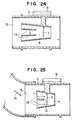
- Fig. 22 is a sectional view of the device
- Fig. 23 is an end view of the device as viewed from the upstream side
- Fig. 24 is a sectional view of the device which presents almost the same appearance as the device shown in Fig. 23 when viewed from the upstream side.
- the device shown in Fig. 22 has a stepped inlet surface for the sub-air passage 4, and a partition wall 13 which divides the interior of the sub-air passage into two portions is provided at the step of the inlet surface.
- This partition wall terminates at a point upstream of the flow rate measuring element 7 so that two portions of the sub-air passage join each other.
- the flow rate measuring element 7 is elongated in a direction substantially perpendicular to the partition wall 13 by a length large enough to receive fractions of air introduced through both portions of the sub-air passage.
- This device is intended to flatten as much as possible the flow velocity distribution pattern over a wide cross-sectional area of the main air passage and to measure the flow rate of the air on the basis of the flattened flow velocity distribution pattern by using the elongated flow rate measuring element, thereby diminishing degradation of the measuring performance attributable to local fluctuation of the measuring characteristics of the flow rate measuring element.
- Measuring error due to uneven flow velocity distribution upstream of the measuring device can generally be reduced by widening the area of measurement by the flow rate measuring element. Such enlargement of the measuring area, however, tends to impair the measuring performance due to local variation of the measuring conditions of the flow rate measuring element.
- the flow rate measuring element has homogeneous structure, different measuring results are obtained at different portions of the flow rate measuring element For instance, the measuring result obtained at the base or supported end portion of the flow rate measuring element is different from that obtained from the free end portion of the same. No substantial problem will be caused by local variation, if the flow of air impinging upon the flow rate measuring element has a uniform flow velocity distribution. Actually, however, different portions of the wide measuring area of the element receive air flow components of different flow velocities. Therefore, a mere widening of the measuring area cannot provide sufficient improvement in the measuring accuracy.
- the widening of the measuring area under non-uniform flow velocity distribution affects not only the measuring accuracy but also response of the flow rate measuring device to change in the flow rate, as well as secular change in the measuring performance due to, for example, deposition of foreign matters on the measuring element.
- the device shown in Fig. 22 employs a configuration of the sub-air passage 4 which can effectively be adopted when the air flowing through the main air passage has such a non-uniform flow velocity pattern that the velocity is higher in the region of the main air passage 5 closer to the circuit module 9, I.e., upper region as viewed in Fig. 22, than in the opposite region, i.e., the lower region as viewed in Fig. 22.
- the flow rate measuring device is devoid of the sub-air passage 4 or that the inlet surface of the sub-air passage 4 Is neither stepped nor parted.
- the upper portion of the flow rate measuring element 7 receives air of greater velocity while the lower portion of the same receives air of smaller flow velocity, as a result of the above-mentioned non-uniform flow velocity distribution pattern, posing a risk of degradation of the measuring performance described before.
- the air flow component in the lower region having smaller flow velocity is preferentially taken into the sub-air passage, by virtue of the fact that the inlet surface for the sub-air passage is stepped and parted. Consequently, the difference between the velocity of air flow component colliding with the upper portion of the flow rate measuring element and the velocity of air flow component colliding with the lower portion of the same is reduced so as to suppress the risk of degradation of the measuring performance described before.
- the device shown in Fig. 24 is intended for use in the case where the most ordinary flow velocity distribution pattern exists in the main air passage 5, i.e., when the flow velocity distribution pattern is such that the flow velocity Is highest in the central region around the axis of the main air passage and is low in the peripheral region.
- the inlet surface in this device is stepped such that the central portion of the inlet surface for the sub-air passage 4 around the axis of the main air passage is recessed to the downstream side, so that air is less liable to be introduced through the central portion of the inlet as compared with the peripheral portion of the inlet, thus flattening the pattern of flow velocity distribution of the air impinging upon the flow rate measuring element 7.
- Fig. 25 shows a flow rate measuring device in which the inlet surface of the sub-air passage 4 is flush.
- the principal flow of air is directed as indicated by an arrow 14. Consequently, a non-uniform flow velocity distribution is formed in the body 3 such that the velocity is higher in the region near the lower end of the body 3 than in the region near the upper end of the body 3 as viewed in Fig. 25.
- the free end portion of the flow rate measuring element 7 receives air of velocity considerably higher than that of the air received by the base end portion of the same element 7 adjacent to the circuit module 9, particularly when the flow rate measuring element 7 having a substantial length is used in such a structure that is completely devoid of the sub-air passage 4 or, even if the sub-air passage is provided, the sub-air passage lacks the partition wall 13 at the inlet thereof.
- this problem is overcome by this device in which, as shown in Fig. 25, the partition plate 13 is provided at the inlet of the sub-air passage 4.
- This partition plate effectively changes the flow velocity distribution pattern in the body 3 in such a manner as to reduce the difference between the velocity of the air flow component colliding with the free end portion of the elongated flow rate measuring element and the velocity of the air flow component colliding with the base end portion of the same. Consequently, the measuring condition is made- more uniform over the area of the flow rate measuring element, thus avoiding degradation in the measuring performance attributable to the use of elongated measuring element.
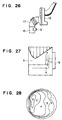
- Figs. 26 to 30 illustrate typical example of non-uniform flow velocity distribution which is caused by the presence of an air cleaner in an intake system of an automotive engine.
- Fig. 26 shows upstream portion of the intake system including an air cleaner housing 16 incorporating an air filter, a duct 17 forming a bent conduit connected to the outlet of the air cleaner housing 16, and an air flow rate measuring device connected to the downstream end of the duct 17.
- Fig. 27 schematically illustrates the pattern of flow velocity distribution which is formed in the region immediately upstream of the air flow rate measuring device by the presence of the intake system shown in Fig. 26.
- Fig. 28 is an equi-velocity diagram illustrative of the flow velocity distribution pattern obtained through an actual measurement in the region downstream of the intake system of Fig. 26, i.e., immediately upstream of the air flow rate measuring device. Greater numerals appearing in this diagram represent higher flow velocities of the air.
- Fig. 29 shows another example of the intake system in which a straight duct 17 is connected to the outlet of the air cleaner housing 16
- Fig. 30 shows the pattern of flow velocity distribution pattern formed by the intake system of Fig. 29,
- Fig. 31 is an equi-velocity diagram showing flow velocity distribution based on velocity data as obtained by actual measurement in the region downstream of the intake system.
- an airflow rate measuring device of the type using a heat-generating resistor as the measuring element measures the total flow rate on the basis of a fraction or flow component which collides with small measuring element.
- the small measuring element 7 measures, as a representative value of the total air flow rate, the flow rate of the flow component which directly contacts the small measuring element 7. Consequently, a significant error tends to be involved in the measurement output particularly when there is a large difference in the flow velocity exists in the flow of air upstream of the flow rate measuring device.
- This problem would be overcome if a plurality of flow rate measuring elements are employed to measure the flow rates at different locations or when a flow rate measuring element having a length large enough to cover a wide region is employed.
- the use of many flow rate measuring elements or long element is not preferred from the view points of production cost and producibility, and may adversely affect the performance of the whole system.
- the present invention proposes to reduce the error or deviation of the measuring output attributable to the presence of non-uniform flow velocity distribution, by improving the construction of the air passages, without being accompanied by the above-described problems which are unavoidable when many flow rate measuring elements or a single element having a substantial length is used.
- the deviation of the measuring output is compensated for by making use of difference between the velocity of air in the main air passage immediately upstream of the inlet of the sub-air passage and the velocity of air in the main air passage immediately upstream of the outlets of the sub-air passage.
- a difference in the flow velocity is positively created by, for example, the provision of protrusions provided on both side surfaces of the structure defining the sub-air passage at positions immediately upstream of the outlets of the sub-air passage.
- the deviation of the measuring output is compensated for by the specific construction which enables air to be introduced into the flow rate measuring portion from different regions of the inlet while giving selectivity or preference of a specific order to these different regions.
- selectivity or preference can be realized, for example, by adopting a stepped inlet surface in which inlet opening leading to the flow rate measuring portion opens.
- a mere widening of the inlet area to capture air from a wide region or a mere passage structure for joining flow components from different regions is impractical because such a measure causes a large drop of pressure.
- the influence of non-uniform flow velocity distribution pattern existing upstream of the flow rate measuring device is effectively diminished simply by modifying the bridge portion which is used in known air flow rate measuring device of the kind described.
- the flow velocity distribution over the cross-section perpendicular to the principal flow of the air exhibits such a pattern that the fraction or component of the highest velocity appears in the core region around the axis of the main air passage, i.e., the center of the above-mentioned cross-section.
- the influence of the non-uniform flow velocity distribution would be remarkably diminished if the flow velocity distribution pattern is flattened in such a manner as to reduce the influence of the central fraction or component of air flow of the highest velocity.
- this could be done by providing a groove-like inlet for the sub-air passage on the upstream end of the bridge, with the bottom of the groove tapered to guide the air to the flow rate measuring portion.
- the bottom of the groove has to be inclined by a large angle from the plane perpendicular to the principal flow of air in the main air passage, with the result that the axial length of the airflow rate measuring device is inconveniently increased, causing various problems such as difficulty encountered in the mounting, rise in the production cost and undesirable effect on the performance of the whole system.
- the inlet surface is modified only by such a degree that does not cause above-described problems. Namely, the inlet surface is simply stepped so as to enable adjustment or control of rates of introduction of air to the flow rate measuring portion from different regions of the inlet opening.
- the positions of the inlet and the outlet of the sub-air passage are determined such that a large difference in the flow velocity is developed between the regions which are immediately upstream of the inlet and the outlet, e.g., such that the inlet and outlet are located at two points which are in symmetry with each other with respect to the axis of the main air passage or such that the inlet is located on the axis while the outlet is located on the axis while the outlet is located at a point near the wall of the body defining the main air passage.
- flow impediment portions such as protrusions provided on the side surfaces of the bridge at positions immediately upstream of the outlets of the sub-air passage are used, so that an automatic canceling or compensation function is performed to cancel the influence of the air flow component introduced from the region around the axis of the main air passage by the fact that, when the velocity of such central air flow component is increased tending to increase the rate of introduction of such component into the flow rate measuring portion, the pressure established immediately downstream of the protrusions is relatively elevated due to reduced air velocity in this region, thus suppressing the rate of introduction of the central flow component of the air into the flow rate measuring portion.
- Fig. 32 shows an engine control system incorporating an air flow rate measuring device, denoted by 101, which produces a signal indicative of the flow rate of the intake air.
- the signal is input to a control unit 102 which computes fuel injection rate and timing based on the detected intake air flow rate.
- the control unit 102 delivers signal indicative of the injection rate and timing to an injector 105.
- Numeral 103 denotes a throttle body which controls the flow rate of the intake air.
- intake air flow rate is measured by the flow rate measuring device 101 without being affected by the construction of the whole system, so that the precision of control of the whole system can be enhanced.
- air can be introduced into the flow rate measuring portion of the sub-air passage from various regions of a cross-section of the main air passage perpendicular to the direction of principal flow of air, while giving preselected order of preference to these regions, thus making it possible to obtain an air flow rate measuring device which can provide a measuring output which is not substantially influenced by the pattern of flow velocity distribution in the region upstream of the flow rate measuring device.
Landscapes
- Physics & Mathematics (AREA)
- General Physics & Mathematics (AREA)
- Fluid Mechanics (AREA)
- Chemical & Material Sciences (AREA)
- Analytical Chemistry (AREA)
- Measuring Volume Flow (AREA)
- Combined Controls Of Internal Combustion Engines (AREA)
Claims (6)
- Dispositif de mesure d'un débit d'air comportant
un passage d'air principal (5) pour l'air d'aspiration,
un élément en forme de pont (2) monté dans ledit passage d'air principal (5), ledit élément en forme de pont (2) ayant une face frontale dirigée dans une direction opposée à la direction prévue d'un écoulement d'air et des faces latérales s'étendant généralement en direction dudit écoulement d'air, dans lequel ledit élément en forme de pont (2) définit un sous-passage d'air (4) permettant à une partie de l'air passant dans le passage d'air principal (5) de passer dans le sous-passage d'air, une portion de mesure de débit étant prévue à l'intérieur dudit sous-passage d'air (4), ledit sous-passage d'air (4) comportant une entrée (4a) sur ladite face frontale de l'élément en forme de pont (2) et une sortie (4b) radialement espacée de l'entrée (4a),
caractérisé par
un moyen de réduction de la résistance à l'écoulement (1) formé par une dite face latérale pourvue d'une protubérance de section substantiellement triangulaire, ladite protubérance ayant une surface inclinée, l'inclinaison de ladite surface inclinée étant dirigée à l'opposé d'un plan généralement parallèle à la direction de l'écoulement et la surface étant disposée en amont de la sortie (4b) du sous-passage d'air (4) pour dévier l'écoulement d'air dans ledit passage d'air principal (5) de manière à l'écarter de la sortie (4b), afin de modifier la résistance imposée par l'écoulement d'air principal dans ledit passage d'air principal (5) sur l'écoulement d'air provenant dudit sous-passage d'air (4) à travers la sortie ( 4b), la résistance décroissant avec une augmentation de l'écoulement d'air principal,
ladite sortie (4b) dudit sous-passage d'air (4) s'ouvrant dans une direction substantiellement orthogonale à la direction de l'écoulement d'air principal dans ledit passage d'air principal (5). - Dispositif de mesure d'un débit d'air selon la revendication 1, dans lequel l'entrée (4a) et la sortie (4b) du sous-passage d'air (4) sont situées à des positions différentes par rapport à des plans transversaux perpendiculaires à la direction de l'écoulement d'air principal dans le passage d'au principal (5).
- Dispositif de mesure d'un débit d'air selon la revendication 1 ou 2, dans lequel l'entrée (4a) du sous-passage d'air (4) comporte un orifice contenant l'axe dudit passage d'air principal (5), alors que la sortie (4b) dudit sous-passage d'air (4) est disposée au voisinage de la paroi définissant le passage d'air principal (5).
- Dispositif de mesure d'un débit d'air selon l'une quelconque des revendications 1 à 3, dans lequel la sortie (4b) est prévue dans une surface d'extrémité en aval ou dans une surface latérale du pont (2).
- Dispositif de mesure d'un débit d'air selon l'une quelconque des revendications 1 à 4, dans lequel une paire desdites sorties (4b) est prévue et une paire desdites protubérances inclinées (1) est formée en symétrie sur les deux faces latérales du pont (2).
- Système de commande du carburant pour un moteur à combustion interne, comprenant:un dispositif de mesure d'un débit d'air selon l'une quelconque des revendications 1 à 5,des moyens (105) d'injection de carburant pour injecter un carburant à un taux et à une synchronisation contrôlés; etune unité de contrôle (102) pour recevoir un signal dudit dispositif de mesure d'un débit d'air indiquant le débit d'air d'aspiration et pour calculer le taux et la synchronisation d'injection à la base dudit signal et délivrant le résultat du calcul au dispositif d'injection de carburant.
Applications Claiming Priority (12)
| Application Number | Priority Date | Filing Date | Title |
|---|---|---|---|
| JP24762692 | 1992-09-17 | ||
| JP24762692 | 1992-09-17 | ||
| JP247626/92 | 1992-09-17 | ||
| JP249504/92 | 1992-09-18 | ||
| JP24950492 | 1992-09-18 | ||
| JP24950492 | 1992-09-18 | ||
| JP29247892 | 1992-10-30 | ||
| JP292478/92 | 1992-10-30 | ||
| JP29247892 | 1992-10-30 | ||
| JP5837193 | 1993-03-18 | ||
| JP5058371A JP2846207B2 (ja) | 1992-09-17 | 1993-03-18 | 空気流量測定装置 |
| JP58371/93 | 1993-03-18 |
Publications (4)
| Publication Number | Publication Date |
|---|---|
| EP0588626A2 EP0588626A2 (fr) | 1994-03-23 |
| EP0588626A3 EP0588626A3 (en) | 1995-08-30 |
| EP0588626B1 EP0588626B1 (fr) | 2000-12-13 |
| EP0588626B2 true EP0588626B2 (fr) | 2003-08-13 |
Family
ID=27463644
Family Applications (1)
| Application Number | Title | Priority Date | Filing Date |
|---|---|---|---|
| EP93307289A Expired - Lifetime EP0588626B2 (fr) | 1992-09-17 | 1993-09-16 | Dispositif de mesure de débit d'air |
Country Status (5)
| Country | Link |
|---|---|
| US (2) | US5467648A (fr) |
| EP (1) | EP0588626B2 (fr) |
| JP (1) | JP2846207B2 (fr) |
| KR (1) | KR100321323B1 (fr) |
| DE (1) | DE69329744T3 (fr) |
Families Citing this family (58)
| Publication number | Priority date | Publication date | Assignee | Title |
|---|---|---|---|---|
| US5789673A (en) * | 1993-09-14 | 1998-08-04 | Hitachi, Ltd. | Thermal type air flow measuring instrument for internal combustion engine |
| US5939628A (en) * | 1995-05-30 | 1999-08-17 | Hitachi, Ltd. | Thermal type air flow measuring instrument for internal combustion engine |
| JP3260552B2 (ja) * | 1994-05-30 | 2002-02-25 | 株式会社日立製作所 | 発熱抵抗式空気流量測定装置 |
| JP3193837B2 (ja) * | 1994-10-18 | 2001-07-30 | 株式会社日立製作所 | 発熱抵抗式流量測定装置 |
| DE4441874A1 (de) * | 1994-11-24 | 1996-05-30 | Bosch Gmbh Robert | Vorrichtung zur Messung der Masse eines strömenden Mediums |
| JPH08219838A (ja) * | 1995-02-15 | 1996-08-30 | Hitachi Ltd | 空気流量測定装置 |
| US5563340A (en) * | 1995-03-28 | 1996-10-08 | Ford Motor Company | Mass air flow sensor housing |
| US5569846A (en) * | 1995-05-03 | 1996-10-29 | Ford Motor Company | Modular apparatus for iteratively evaluating combustion flow process |
| DE19517676B4 (de) * | 1995-05-13 | 2008-01-31 | Robert Bosch Gmbh | Drucksensor für eine Brennkraftmaschine mit einem Ansaugrohr |
| JP3475579B2 (ja) * | 1995-06-20 | 2003-12-08 | 株式会社デンソー | 吸気温センサの取付構造およびそれを用いた熱式流量計 |
| DE19547915A1 (de) * | 1995-12-21 | 1997-06-26 | Bosch Gmbh Robert | Vorrichtung zur Messung der Masse eines strömenden Mediums |
| JP2933871B2 (ja) * | 1996-02-28 | 1999-08-16 | 三菱電機株式会社 | カルマン渦式流量計 |
| US5804718A (en) * | 1996-04-24 | 1998-09-08 | Denso Corporation | Airflow meter having an inverted u-shape bypass passage |
| JP3527813B2 (ja) * | 1996-09-02 | 2004-05-17 | 株式会社日立製作所 | 発熱抵抗体式空気流量測定装置 |
| JP3292817B2 (ja) * | 1997-04-24 | 2002-06-17 | 三菱電機株式会社 | 感熱式流量センサ |
| US6672146B1 (en) * | 1997-09-11 | 2004-01-06 | Hitachi, Ltd. | Thermal resistor type air flow measuring apparatus |
| DE19741031A1 (de) | 1997-09-18 | 1999-03-25 | Bosch Gmbh Robert | Vorrichtung zur Messung der Masse eines strömenden Mediums |
| JP3783896B2 (ja) * | 1997-10-13 | 2006-06-07 | 株式会社デンソー | 空気流量測定装置 |
| JP3758111B2 (ja) * | 1998-03-06 | 2006-03-22 | 株式会社デンソー | 空気流量測定装置 |
| DE19815656A1 (de) * | 1998-04-08 | 1999-10-14 | Bosch Gmbh Robert | Meßvorrichtung zum Messen der Masse eines strömenden Mediums |
| DE19815654A1 (de) * | 1998-04-08 | 1999-10-14 | Bosch Gmbh Robert | Meßvorrichtung zum Messen der Masse eines in einer Leitung strömenden Mediums |
| JP3988307B2 (ja) | 1999-03-26 | 2007-10-10 | 株式会社Sumco | シリコン単結晶、シリコンウェーハ及びエピタキシャルウェーハ |
| KR20010039993A (ko) * | 1999-10-06 | 2001-05-15 | 오카무라 가네오 | 유량 및 유속 측정장치 |
| DE10015918A1 (de) * | 2000-03-30 | 2001-10-04 | Bosch Gmbh Robert | Vorrichtung zur Bestimmung von zumindest einem Parameter eines in einer Leitung strömenden Mediums |
| JP2002005713A (ja) * | 2000-04-17 | 2002-01-09 | Denso Corp | 空気流量測定装置 |
| DE10019149B4 (de) * | 2000-04-18 | 2007-06-06 | Robert Bosch Gmbh | Vorrichtung zur Bestimmung zumindest eines Parameters eines strömenden Mediums |
| DE10046943A1 (de) * | 2000-09-21 | 2002-04-18 | Siemens Ag | Massenstrommesser |
| US6474154B2 (en) * | 2001-01-05 | 2002-11-05 | Ngk Spark Plug Co., Ltd. | Flow measurement device for measuring flow rate and flow velocity |
| DE10135142A1 (de) * | 2001-04-20 | 2002-10-31 | Bosch Gmbh Robert | Vorrichtung zur Bestimmung zumindest eines Parameters eines in einer Leitung strömenden Mediums |
| DE10144327C1 (de) * | 2001-09-10 | 2002-12-12 | Siemens Ag | Luftmassendurchflussmesser mit Strömungselementen |
| JP3764860B2 (ja) * | 2001-09-11 | 2006-04-12 | 株式会社日立製作所 | 流量計測装置 |
| US6622555B2 (en) | 2001-10-11 | 2003-09-23 | Visteon Global Technologies, Inc. | Fluid flow meter |
| US6708561B2 (en) | 2002-04-19 | 2004-03-23 | Visteon Global Technologies, Inc. | Fluid flow meter having an improved sampling channel |
| US6826955B2 (en) * | 2002-09-20 | 2004-12-07 | Visteon Global Technologies, Inc. | Mass fluid flow sensor having an improved housing design |
| US6835234B2 (en) * | 2002-12-12 | 2004-12-28 | Visteon Global Technologies, Inc. | Intake tube assembly with evaporative emission control device |
| US6973825B2 (en) * | 2003-02-24 | 2005-12-13 | Visteon Global Technologies, Inc. | Hot-wire mass flow sensor with low-loss bypass passage |
| DE10316450B4 (de) * | 2003-04-10 | 2019-08-08 | Robert Bosch Gmbh | Vorrichtung zur Bestimmung wenigstens eines Parameters eines in einer Leitung strömenden Mediums |
| JP3848934B2 (ja) * | 2003-05-16 | 2006-11-22 | 三菱電機株式会社 | 空気流量測定装置 |
| US6920784B2 (en) * | 2003-06-18 | 2005-07-26 | Visteon Global Technologies, Inc. | Flow conditioning device |
| US7047805B2 (en) | 2004-04-09 | 2006-05-23 | Visteon Global Technologies, Inc. | Fluid flow meter having an auxiliary flow passage |
| US7281511B2 (en) * | 2005-03-07 | 2007-10-16 | Anthony Quezada | Air intake for motor vehicles |
| JP4752472B2 (ja) * | 2005-12-02 | 2011-08-17 | 株式会社デンソー | 空気流量測定装置 |
| JP4979262B2 (ja) * | 2006-05-08 | 2012-07-18 | 日立オートモティブシステムズ株式会社 | 流量測定装置 |
| DE102006024745A1 (de) * | 2006-05-26 | 2007-12-06 | Siemens Ag | Massenstromsensorvorrichtung |
| JP4341645B2 (ja) | 2006-06-06 | 2009-10-07 | 株式会社日立製作所 | 流量測定装置,流量測定通路及び空気流量測定装置 |
| DE102006045656A1 (de) * | 2006-09-27 | 2008-04-03 | Robert Bosch Gmbh | Strömungsdynamisch verbesserter Steckfühler |
| JP5047079B2 (ja) | 2008-07-02 | 2012-10-10 | 三菱電機株式会社 | 流量測定装置 |
| DE102009054082A1 (de) * | 2009-11-20 | 2011-05-26 | Mahle International Gmbh | Messvorrichtung, Frischluftkanal, Frischluftanlage und Strömungsführungselement |
| JP5263324B2 (ja) * | 2011-03-24 | 2013-08-14 | 株式会社デンソー | 空気流量測定装置 |
| JP2013024710A (ja) * | 2011-07-20 | 2013-02-04 | Denso Corp | 空気流量測定装置 |
| JP5799682B2 (ja) * | 2011-09-05 | 2015-10-28 | 株式会社デンソー | 空気流量測定装置 |
| US9689357B2 (en) | 2013-11-15 | 2017-06-27 | Quirt Evan Crawford | Method and apparatus for improving engine performance |
| DE112015001846B4 (de) | 2014-04-17 | 2023-05-25 | Cummins Filtration Ip, Inc. | Filterbaugruppe mit Konditioniervorrichtung zum Verbessern der Signalqualität eines Luftmassenstromsensors |
| JP6690899B2 (ja) * | 2015-06-29 | 2020-04-28 | 株式会社デンソー | 空気流量測定装置 |
| WO2018075234A1 (fr) | 2016-10-20 | 2018-04-26 | Cummins Filtration Ip, Inc. | Dispositif de conditionnement de flux d'air |
| GB2617625A (en) * | 2017-10-30 | 2023-10-18 | Zehnder Group Uk Ltd | Air flow sensor |
| JP7005856B2 (ja) * | 2017-11-20 | 2022-01-24 | ミネベアミツミ株式会社 | 気流測定装置、及びこれを用いた環境測定装置 |
| DE102021120883A1 (de) * | 2021-08-11 | 2023-02-16 | Sick Ag | Bestimmung des Durchflusses eines strömenden Fluids |
Citations (11)
| Publication number | Priority date | Publication date | Assignee | Title |
|---|---|---|---|---|
| US3314290A (en) † | 1965-07-26 | 1967-04-18 | Technion Res & Dev Foundation | Shunt flow meter |
| DE2653359A1 (de) † | 1975-11-24 | 1977-05-26 | Agar Instr | Vorrichtung und verfahren zur bestimmung eines stroemungsmedium-flusses und/oder zur durchfuehrung einer davon abhaengigen regelung |
| US4527423A (en) † | 1982-02-08 | 1985-07-09 | Hitachi, Ltd. | Air flow meter for internal-combustion engine |
| EP0173946A1 (fr) † | 1984-09-07 | 1986-03-12 | Hitachi, Ltd. | Débitmètre d'air |
| US4612895A (en) † | 1983-09-07 | 1986-09-23 | Hitachi, Ltd. | Fuel flow detector and fuel controller using fuel flow detector |
| US4776213A (en) † | 1987-03-18 | 1988-10-11 | Ford Motor Company | Mass airflow meter |
| EP0295647A1 (fr) † | 1987-06-17 | 1988-12-21 | Hitachi, Ltd. | Débitmètre d'air du type à fil chaud. |
| US4911009A (en) † | 1987-10-09 | 1990-03-27 | Hitachi, Ltd. | Thermal air flow meter |
| US4974445A (en) † | 1987-10-23 | 1990-12-04 | Hitachi, Ltd. | Hot wire type of air flow meter and internal combustion engine using the same |
| EP0458081A2 (fr) † | 1990-04-26 | 1991-11-27 | Nippondenso Co., Ltd. | Débitmètre d'air |
| EP0487346A2 (fr) † | 1990-11-21 | 1992-05-27 | Hitachi, Ltd. | Débimètre d'air |
Family Cites Families (4)
| Publication number | Priority date | Publication date | Assignee | Title |
|---|---|---|---|---|
| JPS5677716A (en) * | 1979-11-29 | 1981-06-26 | Hitachi Ltd | Detector for amount of sucked air |
| US4449401A (en) * | 1981-05-19 | 1984-05-22 | Eaton Corporation | Hot film/swirl fluid flowmeter |
| JP2694664B2 (ja) * | 1989-03-07 | 1997-12-24 | 株式会社日立製作所 | 熱線式空気流量計及び該流量計を備えた内燃機関 |
| US5179858A (en) * | 1990-05-17 | 1993-01-19 | Atwood Robert K | Mass air flow meter |
-
1993
- 1993-03-18 JP JP5058371A patent/JP2846207B2/ja not_active Expired - Lifetime
- 1993-09-14 US US08/120,542 patent/US5467648A/en not_active Expired - Lifetime
- 1993-09-16 KR KR1019930018587A patent/KR100321323B1/ko not_active Expired - Fee Related
- 1993-09-16 DE DE69329744T patent/DE69329744T3/de not_active Expired - Lifetime
- 1993-09-16 EP EP93307289A patent/EP0588626B2/fr not_active Expired - Lifetime
-
1995
- 1995-08-14 US US08/514,851 patent/US5631415A/en not_active Expired - Lifetime
Patent Citations (11)
| Publication number | Priority date | Publication date | Assignee | Title |
|---|---|---|---|---|
| US3314290A (en) † | 1965-07-26 | 1967-04-18 | Technion Res & Dev Foundation | Shunt flow meter |
| DE2653359A1 (de) † | 1975-11-24 | 1977-05-26 | Agar Instr | Vorrichtung und verfahren zur bestimmung eines stroemungsmedium-flusses und/oder zur durchfuehrung einer davon abhaengigen regelung |
| US4527423A (en) † | 1982-02-08 | 1985-07-09 | Hitachi, Ltd. | Air flow meter for internal-combustion engine |
| US4612895A (en) † | 1983-09-07 | 1986-09-23 | Hitachi, Ltd. | Fuel flow detector and fuel controller using fuel flow detector |
| EP0173946A1 (fr) † | 1984-09-07 | 1986-03-12 | Hitachi, Ltd. | Débitmètre d'air |
| US4776213A (en) † | 1987-03-18 | 1988-10-11 | Ford Motor Company | Mass airflow meter |
| EP0295647A1 (fr) † | 1987-06-17 | 1988-12-21 | Hitachi, Ltd. | Débitmètre d'air du type à fil chaud. |
| US4911009A (en) † | 1987-10-09 | 1990-03-27 | Hitachi, Ltd. | Thermal air flow meter |
| US4974445A (en) † | 1987-10-23 | 1990-12-04 | Hitachi, Ltd. | Hot wire type of air flow meter and internal combustion engine using the same |
| EP0458081A2 (fr) † | 1990-04-26 | 1991-11-27 | Nippondenso Co., Ltd. | Débitmètre d'air |
| EP0487346A2 (fr) † | 1990-11-21 | 1992-05-27 | Hitachi, Ltd. | Débimètre d'air |
Also Published As
| Publication number | Publication date |
|---|---|
| JP2846207B2 (ja) | 1999-01-13 |
| DE69329744D1 (de) | 2001-01-18 |
| KR100321323B1 (ko) | 2002-06-20 |
| US5631415A (en) | 1997-05-20 |
| EP0588626A3 (en) | 1995-08-30 |
| KR940007516A (ko) | 1994-04-27 |
| DE69329744T3 (de) | 2004-04-29 |
| DE69329744T2 (de) | 2001-05-23 |
| JPH06194199A (ja) | 1994-07-15 |
| US5467648A (en) | 1995-11-21 |
| EP0588626B1 (fr) | 2000-12-13 |
| EP0588626A2 (fr) | 1994-03-23 |
Similar Documents
| Publication | Publication Date | Title |
|---|---|---|
| EP0588626B2 (fr) | Dispositif de mesure de débit d'air | |
| JPH0475385B2 (fr) | ||
| US6234015B1 (en) | Flow rate measuring device | |
| KR20020085838A (ko) | 분류식 유량계 | |
| US5029465A (en) | Vortex flowmeter | |
| US5052229A (en) | Vortex flowmeter | |
| US6101869A (en) | Air flow rate measuring device for an internal combustion engine | |
| JP2002506529A (ja) | 流動媒体の質量を測定するための装置 | |
| US20020148303A1 (en) | Device for measuring at least one parameter of a flowing medium | |
| JP3245362B2 (ja) | 空気流量測定装置用整流格子 | |
| KR100538060B1 (ko) | 공기 유량 측정 장치 | |
| CN100414264C (zh) | 具有传感器的空气流量测量装置 | |
| US5201216A (en) | Air flow meter for internal combustion engines and a manufacturing method thereof | |
| JP3053176B2 (ja) | 空気流量測定装置 | |
| JP3649258B2 (ja) | 空気流量測定装置 | |
| JPH0718726B2 (ja) | 内燃機関用空気流量計及びその製造方法 | |
| JPH09287991A (ja) | 空気流量測定装置 | |
| JP2000180235A (ja) | 空気流量測定装置 | |
| KR100255475B1 (ko) | 유량계 | |
| JP3070642B2 (ja) | 流量計 | |
| JP2981058B2 (ja) | 流量計 | |
| JP2921150B2 (ja) | 熱式空気流量計 | |
| JP2851884B2 (ja) | 熱式空気流量計 | |
| JP2786708B2 (ja) | 流量測定装置及びこれを含む自動車用スロットルボディー | |
| JP3070641B2 (ja) | 流量計 |
Legal Events
| Date | Code | Title | Description |
|---|---|---|---|
| PUAI | Public reference made under article 153(3) epc to a published international application that has entered the european phase |
Free format text: ORIGINAL CODE: 0009012 |
|
| 17P | Request for examination filed |
Effective date: 19931011 |
|
| AK | Designated contracting states |
Kind code of ref document: A2 Designated state(s): DE GB |
|
| PUAL | Search report despatched |
Free format text: ORIGINAL CODE: 0009013 |
|
| AK | Designated contracting states |
Kind code of ref document: A3 Designated state(s): DE GB |
|
| 17Q | First examination report despatched |
Effective date: 19961021 |
|
| GRAG | Despatch of communication of intention to grant |
Free format text: ORIGINAL CODE: EPIDOS AGRA |
|
| GRAG | Despatch of communication of intention to grant |
Free format text: ORIGINAL CODE: EPIDOS AGRA |
|
| GRAH | Despatch of communication of intention to grant a patent |
Free format text: ORIGINAL CODE: EPIDOS IGRA |
|
| GRAH | Despatch of communication of intention to grant a patent |
Free format text: ORIGINAL CODE: EPIDOS IGRA |
|
| GRAA | (expected) grant |
Free format text: ORIGINAL CODE: 0009210 |
|
| AK | Designated contracting states |
Kind code of ref document: B1 Designated state(s): DE GB |
|
| REF | Corresponds to: |
Ref document number: 69329744 Country of ref document: DE Date of ref document: 20010118 |
|
| EN | Fr: translation not filed | ||
| PLBI | Opposition filed |
Free format text: ORIGINAL CODE: 0009260 |
|
| 26 | Opposition filed |
Opponent name: ROBERT BOSCH GMBH Effective date: 20010508 |
|
| PLBF | Reply of patent proprietor to notice(s) of opposition |
Free format text: ORIGINAL CODE: EPIDOS OBSO |
|
| PLBF | Reply of patent proprietor to notice(s) of opposition |
Free format text: ORIGINAL CODE: EPIDOS OBSO |
|
| REG | Reference to a national code |
Ref country code: GB Ref legal event code: IF02 |
|
| PLAW | Interlocutory decision in opposition |
Free format text: ORIGINAL CODE: EPIDOS IDOP |
|
| PLAW | Interlocutory decision in opposition |
Free format text: ORIGINAL CODE: EPIDOS IDOP |
|
| PUAH | Patent maintained in amended form |
Free format text: ORIGINAL CODE: 0009272 |
|
| STAA | Information on the status of an ep patent application or granted ep patent |
Free format text: STATUS: PATENT MAINTAINED AS AMENDED |
|
| 27A | Patent maintained in amended form |
Effective date: 20030813 |
|
| AK | Designated contracting states |
Designated state(s): DE GB |
|
| EN | Fr: translation not filed | ||
| PGFP | Annual fee paid to national office [announced via postgrant information from national office to epo] |
Ref country code: GB Payment date: 20120912 Year of fee payment: 20 |
|
| PGFP | Annual fee paid to national office [announced via postgrant information from national office to epo] |
Ref country code: DE Payment date: 20120912 Year of fee payment: 20 |
|
| REG | Reference to a national code |
Ref country code: DE Ref legal event code: R071 Ref document number: 69329744 Country of ref document: DE |
|
| REG | Reference to a national code |
Ref country code: DE Ref legal event code: R071 Ref document number: 69329744 Country of ref document: DE |
|
| REG | Reference to a national code |
Ref country code: GB Ref legal event code: PE20 Expiry date: 20130915 |
|
| PG25 | Lapsed in a contracting state [announced via postgrant information from national office to epo] |
Ref country code: DE Free format text: LAPSE BECAUSE OF EXPIRATION OF PROTECTION Effective date: 20130917 |
|
| PG25 | Lapsed in a contracting state [announced via postgrant information from national office to epo] |
Ref country code: GB Free format text: LAPSE BECAUSE OF EXPIRATION OF PROTECTION Effective date: 20130915 |