EP0588687B1 - System zur Bestimmung von zumindest einem Verkehrsregelungsparameter für Fahrzeuge - Google Patents
System zur Bestimmung von zumindest einem Verkehrsregelungsparameter für Fahrzeuge Download PDFInfo
- Publication number
- EP0588687B1 EP0588687B1 EP93402175A EP93402175A EP0588687B1 EP 0588687 B1 EP0588687 B1 EP 0588687B1 EP 93402175 A EP93402175 A EP 93402175A EP 93402175 A EP93402175 A EP 93402175A EP 0588687 B1 EP0588687 B1 EP 0588687B1
- Authority
- EP
- European Patent Office
- Prior art keywords
- vehicle
- radar
- speed
- elevation
- calculating
- Prior art date
- Legal status (The legal status is an assumption and is not a legal conclusion. Google has not performed a legal analysis and makes no representation as to the accuracy of the status listed.)
- Expired - Lifetime
Links
Images




Classifications
-
- G—PHYSICS
- G08—SIGNALLING
- G08G—TRAFFIC CONTROL SYSTEMS
- G08G1/00—Traffic control systems for road vehicles
- G08G1/01—Detecting movement of traffic to be counted or controlled
-
- G—PHYSICS
- G01—MEASURING; TESTING
- G01S—RADIO DIRECTION-FINDING; RADIO NAVIGATION; DETERMINING DISTANCE OR VELOCITY BY USE OF RADIO WAVES; LOCATING OR PRESENCE-DETECTING BY USE OF THE REFLECTION OR RERADIATION OF RADIO WAVES; ANALOGOUS ARRANGEMENTS USING OTHER WAVES
- G01S13/00—Systems using the reflection or reradiation of radio waves, e.g. radar systems; Analogous systems using reflection or reradiation of waves whose nature or wavelength is irrelevant or unspecified
- G01S13/02—Systems using reflection of radio waves, e.g. primary radar systems; Analogous systems
- G01S13/50—Systems of measurement based on relative movement of target
- G01S13/58—Velocity or trajectory determination systems; Sense-of-movement determination systems
- G01S13/64—Velocity measuring systems using range gates
-
- G—PHYSICS
- G01—MEASURING; TESTING
- G01S—RADIO DIRECTION-FINDING; RADIO NAVIGATION; DETERMINING DISTANCE OR VELOCITY BY USE OF RADIO WAVES; LOCATING OR PRESENCE-DETECTING BY USE OF THE REFLECTION OR RERADIATION OF RADIO WAVES; ANALOGOUS ARRANGEMENTS USING OTHER WAVES
- G01S13/00—Systems using the reflection or reradiation of radio waves, e.g. radar systems; Analogous systems using reflection or reradiation of waves whose nature or wavelength is irrelevant or unspecified
- G01S13/88—Radar or analogous systems specially adapted for specific applications
- G01S13/91—Radar or analogous systems specially adapted for specific applications for traffic control
- G01S13/92—Radar or analogous systems specially adapted for specific applications for traffic control for velocity measurement
-
- G—PHYSICS
- G08—SIGNALLING
- G08G—TRAFFIC CONTROL SYSTEMS
- G08G1/00—Traffic control systems for road vehicles
- G08G1/01—Detecting movement of traffic to be counted or controlled
- G08G1/015—Detecting movement of traffic to be counted or controlled with provision for distinguishing between two or more types of vehicles, e.g. between motor-cars and cycles
Definitions
- the present invention consists of a system for calculating at least minus a vehicle traffic control setting.
- the field more particularly targeted by the invention relates to motor vehicles (cars, trucks ...) circulating on all kinds of roads (highways, national, departmental ).
- motor vehicles cars, trucks
- system which is the subject of the invention can also control river or sea traffic, or objects circulating on a robotic chain. So the term vehicle covers just as well cars, trucks, motorcycles, boats, objects ...
- a first widely used technique consists of place induction loops under the road.
- the variation of the field induced in such loops allows to know if a vehicle has passed or no.
- induction loops work regardless of conditions climatic conditions, day and night.
- establishment of these induction loops is cumbersome and expensive to implement, and it is difficult, if not impossible, to conduct interviews.
- a second technique still at the prototype stage consists in use video cameras associated with processing of the captured images.
- the installation on masts of these cameras is very easy here, but the performances are inconclusive: video cameras do not present the advantage of operating whatever the climatic conditions, and are, moreover, very dependent on the light conditions.
- the algorithms used in image processing are complex and require significant computing power.
- a third known technique consists in positioning a radar, for example on a bridge infrastructure, and detect vehicles as well as their speed by the Doppler effect.
- US Patent US-A-4,985,705 describes a way usual to implement this third traffic analysis technique road using a continuous wave radar. This consists of choosing a continuous wave millimeter radar with antenna having a brush end (3 ° opening horizontally and 13 ° vertical), place it in the above a traffic lane, tilted downward, so that the beam of its antenna only intercepts a portion of this traffic lane and extract the different parameters concerning the traffic of detections of vehicle presences on this lane and speeds of these vehicles deduced from the Doppler effect.
- the disadvantage of this implementation is that it allows you to control only one lane of traffic. On a roadway with several traffic lanes, it is necessary to have as many speed cameras and traffic lanes which can be costly as well in switchgear than in installation.
- the object of the present invention is to overcome the drawbacks and respond to a recent request that increasingly more requirements on the control of a localized area which may present several two-way traffic lanes, for example a motorway.
- the present invention relates to a system calculation of at least one vehicle traffic control parameter which can travel on at least two traffic lanes, as described in claim 1.
- processing module of the radar reception signal is provided with an interleaved smoothing filter between the Fourier transform calculation means and the means of detection.
- Figure 1 is an exemplary embodiment of a control according to the invention:
- a first essential characteristic of the system according to the invention is the use of a pulse radar 1.
- a pulse radar 1 generates indeed the distance information of the detected vehicles. This information can be used for the observation of several ways traffic thanks to a single pulse radar, positioned particular way as we will see later.
- the pulse radar 1 can conventionally comprise a pulse generator 10 of carrier frequency f 0 , transmitting the pulses generated to a transmitter 11, the latter delivering pulses of carrier frequency f 0 to an antenna 13 at the frequency of recurrence F R.
- the radar preferably operates in millimeter waves, the frequency f o possibly belonging to the interval [30 GHz; 100 GHz].
- f o close to either 35 GHz or 94 GHz, values for which the atmospheric absorption is the lowest.
- the same antenna 13 receives echo signals which it transmits, via a circulator 14, to a conventional receiver 15.
- Synchronization 16 allows the transmission-reception unit to function properly, i.e. to receive echo signals only when the radar is not pulsing.
- the appearance of the radiation from antenna 13 and its relative position with respect to the channels that you want to control are those shown on the Figures 2a and 2b which are the top and side views respectively radar coverage in the specific but non-limiting application traffic control on a highway 5 comprising for example six taxiways 5a and a central reservation 5b.
- the system 4 is positioned on a side not common to the traffic lanes 5a.
- the system 4 is positioned in height, for example on a mast, so that the antenna 13 of the radar can overhang the tracks 5a of a given height h.
- this height h greater than the maximum possible height of a motorway vehicle, so that there is no possible masking between two vehicles which should be detected at the same time by the radar, in case the one of the two vehicles closest to the radar has a height superior to the other vehicle.
- the radiation pattern 6 must be narrow in bearing ( Figure 2a) and wide enough in site to cover all the tracks ( Figure 2b).
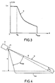
- the radiation diagram in elevation an appearance as shown in FIGS. 2b and 4, for which the diagram 6 has a gain zone 6a dependent on the distance and substantially parallel to the route 5 so that the same vehicle detected at different distances is received with almost the same amplitude by the radar.
- G ( ⁇ ) of gain as a function of the angle in elevation represented by the curve 8 of FIG. 3 has the preceding property.
- the diagram is identical to that of a conventional antenna, that is to say that it has a substantially constant gain G o .
- the echo signals from the receiver 15 of radar 1 are then transmitted to a signal processing module 2 allowing the detection of vehicles by traffic.
- the time samples are then delivered to calculation means 21 of the Fourier transform of these samples, and the samples of frequency from the calculation means 21 are, in accordance with the invention, filtered in amplitude by a smoothing filter 22.
- FIGS. 5a and 5b representing an example of the amplitude of the frequency signal according to the time respectively before filtering 22 and after this filtering, show the need for this filtering.
- Curve 9 in Figure 5a is a example of what is obtained with the system of the invention when only vehicle cuts the diagram, at the output of the calculation means 21 of the Fourier transform.
- This curve 9 presents rapid and significant variations amplitude so that a simple thresholding with respect to a value of given threshold would lead to detecting several vehicles instead of one.
- the amplitude fluctuation illustrated by curve 9 is due to the fluctuation of the radar equivalent surface of the vehicle in waves millimeters to the movement of the vehicle and the change of angle view of this vehicle during its passage through the beam.
- the system according to the invention therefore comprises a smoothing filter 22 of the amplitude of the frequency signal after Fourier transform.
- This filter can for example be a medium filter whose application to a given frequency sample makes it possible to replace the amplitude of this sample by the mean of this amplitude with the amplitudes of an even number of samples taken on either side of said sample given.
- the filtering result is illustrated by the curve 9 ′ in the figure 5b. It is now possible to compare the amplitude of the frequency samples with a given threshold s, thanks to means of comparison 23 illustrated in Figure 1. Each positive comparison is detection of a vehicle on a lane.
- the threshold is either set at advance, be adaptive.
- the system Following the detection of vehicles on each lane from a single radar 1, the system according to the invention provides for calculating one or several traffic parameters. It is equipped for this with a module parameter extraction 3.
- a first example of a parameter to extract is the total number of vehicles per lane or overall detected during a measurement time T TOT . This number can be extracted by means of incrementation 30, connected for example to comparison means 23, and increasing by one unit each time a vehicle is detected.
- the system according to the invention can also extract the length L v of a detected vehicle.
- FIG. 6 shows that it is necessary to make a correction on the length measured by the radar 1. Indeed, the diagram 6 of the radar 1 detects the front of the vehicle A when the latter intercepts the start of the distance box 7 , and detection is carried out until the vehicle leaves this distance box completely. If L cd is the length of the distance box 7, account must be taken of the error it causes.
- n v is the number of vehicles detected over the total duration T TOT , supplied for example by the incrementing means 30, and V i is the speed of a detected vehicle, supplied by the first means 31.
- the signal processing 2 and extraction modules parameters 3 are advantageously implemented in the form of programs IT. Calculations can be done in real time, or in time deferred if the system of storage means is provided 24.
- the performance of the system of the invention is independent of climatic conditions. We can also consider to install several systems on different points of a road or highway, and correlate the results from each system with an information collection station, so as to have a follow-up of traffic development.
- the system can be positioned at points nerve centers of a motorway network (entry or exit ramp, approaching a toll, entering or leaving a rest area ).
Landscapes
- Engineering & Computer Science (AREA)
- Radar, Positioning & Navigation (AREA)
- Remote Sensing (AREA)
- Physics & Mathematics (AREA)
- General Physics & Mathematics (AREA)
- Computer Networks & Wireless Communication (AREA)
- Electromagnetism (AREA)
- Radar Systems Or Details Thereof (AREA)
- Traffic Control Systems (AREA)
Claims (9)
- Rechensystem für die Berechnung von wenigstens einem Parameter für die Kontrolle des Verkehrs von Fahrzeugen, die auf wenigstens zwei Fahrbahnen fahren können, mit einem Radargerät (1), einem Modul (2) für die Verarbeitung des Empfangssignals des Radargeräts, das einen Abtastcodierer (20), Mittel (21) zur Berechnung der Fourier-Transformierten und Erfassungsmittel (23) aufweist, und mit einem Modul (3) zur Gewinnung des Parameters, das ausgehend von den Ausgangssignalen der Erfassungsmittel (23) und der Mittel (21) zur Berechnung der Fourier-Transformierten arbeitet, dadurch gekennzeichnet, daß das Radargerät (1) ein Impulsradargerät ist, mit einem Sender (11) zur Aussendung von Impulsen einer gegebenen Trägerfrequenz f0 und einer Dauer τ, einem Empfänger (15), der außerhalb der Sendeperioden der Impulse arbeitet, und mit einem Strahlungsdiagramm, das dem Seitenwinkel nach schmal und dem Höhenwinkel nach ausreichend groß ist, um die Fahrbahnen zu überdecken und eine gleichzeitige Kontrolle der Fahrbahnen zu ermöglichen, und das um einen Höhenwinkel αs und um einen Seitenwinkel ag geneigt ist, wobei die Werte der Impulsdauer τ, des Höhenwinkels αs und des Seitenwinkels ag so gewählt sind, daß wenigstens ein Entfernungsfenster des Radargeräts in einer Fahrbahn enthalten ist und daß die Mittel zur Berechnung der Fourier-Transformierten mit einer ganzen Zahl N von zeitlichen Abtastwerten arbeiten, die vom Abtastcodierer für jedes Entfernungsfenster entsprechend jeder Fahrbahn abgegeben werden, und daß das Modul (2) für die Verarbeitung des Empfangssignals des Radargeräts mit einem Glättungsfilter (22) für die Amplitude der von den Berechnungsmitteln abgegebenen Frequenzabtastwerte ausgestattet ist, das zwischen die Mittel (21) zur Berechnung der Fourier-Transformierten und die Erfassungsmittel (23) eingefügt ist, die Mittel zum Vergleich der Amplitude der vom Glättungsfilter abgegebenen Abtastwerte mit einem gegebenen Schwellenwert sind, um die Fahrzeugdurchfahrt auf jeder Fahrbahn zu erfassen.
- Rechensystem nach Anspruch 1, dadurch gekennzeichnet, daß das Strahlungsdiagramm (6) dem Höhenwinkel nach einen Gewinn G() aufweist, der sich in Abhängigkeit von dem Höhenwinkel () nach dem Kosekansquadrat gemäß der folgenden Beziehung ändert:G0 der im wesentliche konstante Gewinn des Strahlungsdiagramms für Höhenwinkel ist, die kleiner als 0 sind;0 und max zwei vorbestimmte Höhenwinkelwerte sind.
- Rechensystem nach einem der vorhergehenden Ansprüche, dadurch gekennzeichnet, daß der Parameter die Anzahl n von Fahrzeugen ist, die auf jeder Fahrbahn fahren, und daß das Gewinnungsmodul (3) Inkrementierungsmittel (30) enthält, die jeweils bei der Erfassung eines Fahrzeugs um eine Einheit zunehmen.
- Rechensystem nach einem der Ansprüche 1 bis 3, dadurch gekennzeichnet, daß der Parameter die Geschwindigkeit V eines in einem Geschwindigkeitsbereich Dv erfaßten Fahrzeugs ist und daß das Gewinnungsmodul (3) erste Mittel (31) zur Berechnung dieser Geschwindigkeit enthält, welche die Ordnung f des von Null verschiedenen Frequenzabtastwerts suchen, der der maximalen Amplitude der vom Filter (22) abgegebenen Abtastwerte entspricht, und die Geschwindigkeit V des Fahrzeugs durch Anwendung der folgenden Beziehungen berechnen:worin:

- FR
- die Folgefrequenz des Radargeräts ist,
- c
- die Lichtgeschwindigkeit ist
und - αv
- der Umrechnungsfaktor von m/s in km/h ist, der gleich 3,6 ist.
- Rechensystem nach Anspruch 4, dadurch gekennzeichnet, daß es außerdem die Länge Lv eines erfaßten Fahrzeugs berechnet und daß das Gewinnungsmodul (3) zweite Mittel (32) enthält, welche diese Länge durch Anwendung der folgenden Beziehung berechnen:
- Rechensystem nach einem der Ansprüche 4 oder 5, dadurch gekennzeichnet, daß es außerdem die mittlere Geschwindigkeit Vmoy und die harmonische Geschwindigkeit Vharm aller Fahrzeuge berechnet, die in einer Gesamtmeßdauer TTOT erfaßt werden, und daß das Gewinnungsmodul (3) dritte Mittel (33) enthält, welche diese Geschwindigkeit durch Anwendung der folgenden Beziehungen berechnen:wobei

- nv
- die Anzahl der in der Gesamtdauer erfaßten Fahrzeuge ist,
- Vi
- die Geschwindigkeit eines erfaßten Fahrzeugs ist.
- Rechensystem nach einem der vorhergehenden Ansprüche, dadurch gekennzeichnet, daß das Glättungsfilter (22) ein Filter vom Tiefpaßtyp ist, das die Amplitude jedes von den Mitteln (21) zur Berechnung der Fourier-Transformierten abgegebenen Abtastwerts durch den Mittelwert aus dieser Amplitude und denjenigen einer geraden Anzahl von zu beiden Seiten dieses Abtastwerts entnommenen Abtastwerten ersetzt.
- Rechensystem nach einem der vorhergehenden Ansprüche, dadurch gekennzeichnet, daß die Module für die Verarbeitung (2) und für die Gewinnung (3) mit Hilfe von Speichermitteln (24) zeitversetzt arbeiten.
- Rechensystem nach einem der vorhergehenden Ansprüche, dadurch gekennzeichnet, daß die Höhe h größer als die maximale Höhe ist, die ein Fahrzeug haben kann.
Applications Claiming Priority (2)
| Application Number | Priority Date | Filing Date | Title |
|---|---|---|---|
| FR9210965 | 1992-09-15 | ||
| FR9210965A FR2695742B1 (fr) | 1992-09-15 | 1992-09-15 | Système de calcul d'au moins un paramètre de contrôle de trafic de véhicules. |
Publications (2)
| Publication Number | Publication Date |
|---|---|
| EP0588687A1 EP0588687A1 (de) | 1994-03-23 |
| EP0588687B1 true EP0588687B1 (de) | 1998-03-04 |
Family
ID=9433502
Family Applications (1)
| Application Number | Title | Priority Date | Filing Date |
|---|---|---|---|
| EP93402175A Expired - Lifetime EP0588687B1 (de) | 1992-09-15 | 1993-09-07 | System zur Bestimmung von zumindest einem Verkehrsregelungsparameter für Fahrzeuge |
Country Status (6)
| Country | Link |
|---|---|
| US (1) | US5402346A (de) |
| EP (1) | EP0588687B1 (de) |
| JP (1) | JPH06194443A (de) |
| CA (1) | CA2106115A1 (de) |
| DE (1) | DE69317186T2 (de) |
| FR (1) | FR2695742B1 (de) |
Families Citing this family (56)
| Publication number | Priority date | Publication date | Assignee | Title |
|---|---|---|---|---|
| JP3110095B2 (ja) * | 1991-09-20 | 2000-11-20 | 富士通株式会社 | 測距方法及び測距装置 |
| US5586063A (en) * | 1993-09-01 | 1996-12-17 | Hardin; Larry C. | Optical range and speed detection system |
| FR2718874B1 (fr) * | 1994-04-15 | 1996-05-15 | Thomson Csf | Procédé de surveillance de trafic pour la détection automatique d'incident de véhicules. |
| GB2329293B (en) * | 1994-10-03 | 1999-04-28 | Seiko Precision Kk | Distance measuring apparatus |
| JPH08105742A (ja) * | 1994-10-03 | 1996-04-23 | Seikosha Co Ltd | 測距装置 |
| US5570093A (en) * | 1995-02-10 | 1996-10-29 | Applied Concepts, Inc. | Police traffic radar using absolute signal strength information to improve target signal processing accuracy |
| US5663720A (en) * | 1995-06-02 | 1997-09-02 | Weissman; Isaac | Method and system for regional traffic monitoring |
| DE69720022T2 (de) * | 1996-04-01 | 2004-03-04 | Gatsometer B.V. | Verfahren und vorrichtung zur positions- und geschwindigkeitsbestimmung eines fahrzeugs |
| US6011515A (en) * | 1996-10-08 | 2000-01-04 | The Johns Hopkins University | System for measuring average speed and traffic volume on a roadway |
| US6531982B1 (en) | 1997-09-30 | 2003-03-11 | Sirf Technology, Inc. | Field unit for use in a GPS system |
| US6327471B1 (en) | 1998-02-19 | 2001-12-04 | Conexant Systems, Inc. | Method and an apparatus for positioning system assisted cellular radiotelephone handoff and dropoff |
| US6348744B1 (en) | 1998-04-14 | 2002-02-19 | Conexant Systems, Inc. | Integrated power management module |
| AU6078099A (en) * | 1998-07-17 | 2000-02-07 | Siemens Aktiengesellschaft | Method for detecting a vehicle traffic status and system for detecting said traffic status |
| US7545854B1 (en) * | 1998-09-01 | 2009-06-09 | Sirf Technology, Inc. | Doppler corrected spread spectrum matched filter |
| US7711038B1 (en) | 1998-09-01 | 2010-05-04 | Sirf Technology, Inc. | System and method for despreading in a spread spectrum matched filter |
| US6693953B2 (en) | 1998-09-30 | 2004-02-17 | Skyworks Solutions, Inc. | Adaptive wireless communication receiver |
| US6606349B1 (en) | 1999-02-04 | 2003-08-12 | Sirf Technology, Inc. | Spread spectrum receiver performance improvement |
| US6448925B1 (en) | 1999-02-04 | 2002-09-10 | Conexant Systems, Inc. | Jamming detection and blanking for GPS receivers |
| US6577271B1 (en) | 1999-03-30 | 2003-06-10 | Sirf Technology, Inc | Signal detector employing coherent integration |
| US6304216B1 (en) | 1999-03-30 | 2001-10-16 | Conexant Systems, Inc. | Signal detector employing correlation analysis of non-uniform and disjoint sample segments |
| US6351486B1 (en) | 1999-05-25 | 2002-02-26 | Conexant Systems, Inc. | Accelerated selection of a base station in a wireless communication system |
| US6952440B1 (en) | 2000-04-18 | 2005-10-04 | Sirf Technology, Inc. | Signal detector employing a Doppler phase correction system |
| US6788655B1 (en) | 2000-04-18 | 2004-09-07 | Sirf Technology, Inc. | Personal communications device with ratio counter |
| US6714158B1 (en) * | 2000-04-18 | 2004-03-30 | Sirf Technology, Inc. | Method and system for data detection in a global positioning system satellite receiver |
| US6931055B1 (en) | 2000-04-18 | 2005-08-16 | Sirf Technology, Inc. | Signal detector employing a doppler phase correction system |
| US7885314B1 (en) | 2000-05-02 | 2011-02-08 | Kenneth Scott Walley | Cancellation system and method for a wireless positioning system |
| US6778136B2 (en) * | 2001-12-13 | 2004-08-17 | Sirf Technology, Inc. | Fast acquisition of GPS signal |
| AUPR631801A0 (en) * | 2001-07-12 | 2001-08-02 | Luscombe, Andrew | Roadside sensor system |
| US6693557B2 (en) * | 2001-09-27 | 2004-02-17 | Wavetronix Llc | Vehicular traffic sensor |
| DE10260434A1 (de) * | 2002-12-21 | 2004-07-08 | Volkswagen Ag | Längenmessung mit Radar |
| US6943727B2 (en) * | 2002-10-29 | 2005-09-13 | Volkswagen Ag | Length measurement with radar |
| US7426450B2 (en) * | 2003-01-10 | 2008-09-16 | Wavetronix, Llc | Systems and methods for monitoring speed |
| US20050209762A1 (en) * | 2004-03-18 | 2005-09-22 | Ford Global Technologies, Llc | Method and apparatus for controlling a vehicle using an object detection system and brake-steer |
| US7558695B2 (en) * | 2004-08-10 | 2009-07-07 | Speedinfo, Llc | Self-powered vehicle speed sensor |
| US8370054B2 (en) * | 2005-03-24 | 2013-02-05 | Google Inc. | User location driven identification of service vehicles |
| US7558536B2 (en) * | 2005-07-18 | 2009-07-07 | EIS Electronic Integrated Systems, Inc. | Antenna/transceiver configuration in a traffic sensor |
| US7454287B2 (en) * | 2005-07-18 | 2008-11-18 | Image Sensing Systems, Inc. | Method and apparatus for providing automatic lane calibration in a traffic sensor |
| US7768427B2 (en) * | 2005-08-05 | 2010-08-03 | Image Sensign Systems, Inc. | Processor architecture for traffic sensor and method for obtaining and processing traffic data using same |
| US7474259B2 (en) * | 2005-09-13 | 2009-01-06 | Eis Electronic Integrated Systems Inc. | Traffic sensor and method for providing a stabilized signal |
| US8665113B2 (en) * | 2005-10-31 | 2014-03-04 | Wavetronix Llc | Detecting roadway targets across beams including filtering computed positions |
| US8248272B2 (en) * | 2005-10-31 | 2012-08-21 | Wavetronix | Detecting targets in roadway intersections |
| US7541943B2 (en) * | 2006-05-05 | 2009-06-02 | Eis Electronic Integrated Systems Inc. | Traffic sensor incorporating a video camera and method of operating same |
| US7990313B2 (en) * | 2006-07-13 | 2011-08-02 | Siemens Aktiengesellschaft | Radar arrangement |
| DE102007022372A1 (de) * | 2007-05-07 | 2008-11-13 | Robot Visual Systems Gmbh | Verfahren und Vorrichtung zur Ermittlung der Fahrzeugklasse von Fahrzeugen |
| DE102007022373A1 (de) * | 2007-05-07 | 2008-11-13 | Robot Visual Systems Gmbh | Verfahren zur beweiskräftigen Erfassung der Geschwindigkeit eines Fahrzeuges |
| TW201133412A (en) * | 2010-03-19 | 2011-10-01 | Cct Co Ltd | Method of using radar vehicle detector to determine vehicle type, speed, and radar detection zone width |
| DE102010024152B4 (de) * | 2010-06-17 | 2014-09-18 | Rtb Gmbh & Co. Kg | Anordnung zur Messung der Höhe eines Fahrzeugs |
| HUE025253T2 (en) * | 2011-06-21 | 2016-02-29 | Kapsch Trafficcom Ag | Procedure and apparatus for detecting rotating wheel |
| US9412271B2 (en) | 2013-01-30 | 2016-08-09 | Wavetronix Llc | Traffic flow through an intersection by reducing platoon interference |
| DE102013002994B4 (de) * | 2013-02-22 | 2017-04-27 | S.M.S Smart Microwave Sensors Gmbh | Verfahren und Vorrichtung zum Bestimmen eines Erfassungsbereichs eines Verkehrsweges |
| PT2804014E (pt) * | 2013-05-13 | 2015-09-10 | Kapsch Trafficcom Ag | Dispositivo e método para determinar uma característica de um veículo |
| PL2804013T3 (pl) * | 2013-05-13 | 2015-10-30 | Kapsch Trafficcom Ag | Urządzenie do pomiaru położenia pojazdu albo jego powierzchni |
| JP2015087120A (ja) * | 2013-10-28 | 2015-05-07 | 住友電気工業株式会社 | 電波センサおよび検知方法 |
| FR3050279B1 (fr) * | 2016-04-19 | 2018-05-11 | Thales | Calcul automatique d'une dimension d'une plateforme mobile |
| WO2023119907A1 (ja) * | 2021-12-20 | 2023-06-29 | 住友電気工業株式会社 | 受信装置及び異常検知システム |
| JP7346639B1 (ja) * | 2022-03-22 | 2023-09-19 | シーキューブ株式会社 | 通過検出装置 |
Family Cites Families (9)
| Publication number | Priority date | Publication date | Assignee | Title |
|---|---|---|---|---|
| US3408648A (en) * | 1966-12-02 | 1968-10-29 | Lab For Electronics Inc | Speed sensor |
| GB1315533A (en) * | 1970-06-24 | 1973-05-02 | Pye Ltd | Vehicle monitoring radar apparatus |
| US3876946A (en) * | 1973-10-31 | 1975-04-08 | Singer Co | Radio frequency digital fourier analyzer |
| US4317117A (en) * | 1979-07-20 | 1982-02-23 | Chasek Norman E | Cross correlated doppler radar/infra red velocity and presence sensor |
| FR2517069A1 (fr) * | 1981-11-24 | 1983-05-27 | Lmt Radio Professionelle | Radar doppler de surveillance terrestre |
| FR2622021B1 (fr) * | 1987-10-16 | 1990-05-04 | Trt Telecom Radio Electr | Dispositif pour mesurer la distance " h " qui le separe d'un objet |
| DE3810357A1 (de) * | 1988-03-26 | 1989-10-05 | Licentia Gmbh | Verfahren zur lokalen verkehrsdatenerfassung und -auswertung und vorrichtung zum durchfuehren des verfahrens |
| JP2712844B2 (ja) * | 1990-04-27 | 1998-02-16 | 株式会社日立製作所 | 交通流計測装置及び交通流計測制御装置 |
| US5161107A (en) * | 1990-10-25 | 1992-11-03 | Mestech Creation Corporation | Traffic surveillance system |
-
1992
- 1992-09-15 FR FR9210965A patent/FR2695742B1/fr not_active Expired - Fee Related
-
1993
- 1993-08-25 US US08/112,842 patent/US5402346A/en not_active Expired - Fee Related
- 1993-08-30 JP JP5214238A patent/JPH06194443A/ja active Pending
- 1993-09-07 EP EP93402175A patent/EP0588687B1/de not_active Expired - Lifetime
- 1993-09-07 DE DE69317186T patent/DE69317186T2/de not_active Expired - Fee Related
- 1993-09-14 CA CA002106115A patent/CA2106115A1/fr not_active Abandoned
Also Published As
| Publication number | Publication date |
|---|---|
| FR2695742A1 (fr) | 1994-03-18 |
| EP0588687A1 (de) | 1994-03-23 |
| DE69317186T2 (de) | 1998-06-25 |
| CA2106115A1 (fr) | 1994-03-16 |
| FR2695742B1 (fr) | 1994-10-21 |
| DE69317186D1 (de) | 1998-04-09 |
| US5402346A (en) | 1995-03-28 |
| JPH06194443A (ja) | 1994-07-15 |
Similar Documents
| Publication | Publication Date | Title |
|---|---|---|
| EP0588687A1 (de) | System zur Bestimmung von zumindest einem Verkehrsregelungsparameter für Fahrzeuge | |
| EP0755524B1 (de) | Verfahren zur verkehrüberwachung für die automatische fahrzeug vor fallerkennung | |
| EP0568427B1 (de) | Verfahren und Vorrichtung zur Detektion von einem oder mehreren Objekten in einem Winkelsektor, mit Anwendungen | |
| EP3074786B1 (de) | Antikollisionsradar, insbesondere für ein flugzeug beim rollen, und kollisionsschutzsystem | |
| EP0591497B1 (de) | Verfahren und vorrichtung zur bestimmung der position und der ausrichtung von beweglichen körpern, mit anwendungen | |
| EP3282283A1 (de) | Fmcw-radar-detektionsverfahren mit mehrfachauflösung, und radar zur anwendung dieses verfahrens | |
| EP0658775B1 (de) | Kollisionsschutzeinrichtung für Kraftfahrzeuge | |
| EP0389325B1 (de) | Verfahren und Gerät zur Hilfe des Landfahrzeugverkehrs | |
| EP2096611A1 (de) | Verfahren und Vorrichtung zur Multitechnologie-Erkennung in einem Fahrzeug | |
| EP3945345A1 (de) | Verfahren zur fahrzeugkontrolle mit verschiedenen sensoren | |
| FR2905765A1 (fr) | Dispositif et procede d'estimation des dimensions d'une place de parking, vehicule automobile comportant un tel dispositif. | |
| EP2948790B1 (de) | Fahrerassistenzsystem | |
| EP2377100B1 (de) | Identifizierungssystem für die datensammlung von mindestens einem fahrzeug | |
| FR2880133A1 (fr) | Systeme de radar pour surveiller des cibles dans differentes plages d'eloignement | |
| FR2675610A1 (fr) | Procede et installation d'evaluation d'un flux de circulation de vehicules routiers. | |
| WO2020188158A1 (fr) | Dispositif de communications cooperatives pour systemes de transport associant radars embarques et communications inter vehicules v2v | |
| EP1012625A1 (de) | Verfahren zur kollisionsvemeidung in einem kraftfahrzeug | |
| FR2860930A1 (fr) | Procede et dispositif de filtrage d'un signal video recu par un radar secondaire, notamment pour eliminer les reponses mode s. | |
| FR2487985A1 (fr) | Dispositif et procede d'attaque d'antennes pour un systeme de navigation omnidirectionnelle a tres haute frequence | |
| FR2769978A1 (fr) | Procede de localisation et/ou de mesure de vitesse de vehicules, et dispositif de mise en oeuvre | |
| FR2617315A1 (fr) | Procede et dispositif de discrimination du type d'un vehicule automobile en circulation | |
| FR2646512A1 (de) | ||
| EP3195007B1 (de) | Radarverfahren zur schätzung der grösse von herabfallenden gesteinsblöcken | |
| FR2887635A1 (fr) | Dispositif de localisation de vehicule par transmission radiofrequence | |
| FR2694982A1 (fr) | Système d'identification ami-ennemi protégé contre les intrusions et discriminant. |
Legal Events
| Date | Code | Title | Description |
|---|---|---|---|
| PUAI | Public reference made under article 153(3) epc to a published international application that has entered the european phase |
Free format text: ORIGINAL CODE: 0009012 |
|
| AK | Designated contracting states |
Kind code of ref document: A1 Designated state(s): DE FR GB IT SE |
|
| 17P | Request for examination filed |
Effective date: 19940901 |
|
| 17Q | First examination report despatched |
Effective date: 19960611 |
|
| GRAG | Despatch of communication of intention to grant |
Free format text: ORIGINAL CODE: EPIDOS AGRA |
|
| GRAG | Despatch of communication of intention to grant |
Free format text: ORIGINAL CODE: EPIDOS AGRA |
|
| GRAH | Despatch of communication of intention to grant a patent |
Free format text: ORIGINAL CODE: EPIDOS IGRA |
|
| GRAH | Despatch of communication of intention to grant a patent |
Free format text: ORIGINAL CODE: EPIDOS IGRA |
|
| GRAA | (expected) grant |
Free format text: ORIGINAL CODE: 0009210 |
|
| AK | Designated contracting states |
Kind code of ref document: B1 Designated state(s): DE FR GB IT SE |
|
| ITF | It: translation for a ep patent filed | ||
| REF | Corresponds to: |
Ref document number: 69317186 Country of ref document: DE Date of ref document: 19980409 |
|
| GBT | Gb: translation of ep patent filed (gb section 77(6)(a)/1977) |
Effective date: 19980507 |
|
| PLBE | No opposition filed within time limit |
Free format text: ORIGINAL CODE: 0009261 |
|
| STAA | Information on the status of an ep patent application or granted ep patent |
Free format text: STATUS: NO OPPOSITION FILED WITHIN TIME LIMIT |
|
| 26N | No opposition filed | ||
| PGFP | Annual fee paid to national office [announced via postgrant information from national office to epo] |
Ref country code: SE Payment date: 20000815 Year of fee payment: 8 |
|
| PGFP | Annual fee paid to national office [announced via postgrant information from national office to epo] |
Ref country code: DE Payment date: 20010821 Year of fee payment: 9 |
|
| PGFP | Annual fee paid to national office [announced via postgrant information from national office to epo] |
Ref country code: GB Payment date: 20010822 Year of fee payment: 9 |
|
| PG25 | Lapsed in a contracting state [announced via postgrant information from national office to epo] |
Ref country code: SE Free format text: LAPSE BECAUSE OF NON-PAYMENT OF DUE FEES Effective date: 20010908 |
|
| PGFP | Annual fee paid to national office [announced via postgrant information from national office to epo] |
Ref country code: FR Payment date: 20010925 Year of fee payment: 9 |
|
| REG | Reference to a national code |
Ref country code: GB Ref legal event code: IF02 |
|
| EUG | Se: european patent has lapsed |
Ref document number: 93402175.9 |
|
| PG25 | Lapsed in a contracting state [announced via postgrant information from national office to epo] |
Ref country code: GB Free format text: LAPSE BECAUSE OF NON-PAYMENT OF DUE FEES Effective date: 20020907 |
|
| REG | Reference to a national code |
Ref country code: FR Ref legal event code: CD |
|
| PG25 | Lapsed in a contracting state [announced via postgrant information from national office to epo] |
Ref country code: DE Free format text: LAPSE BECAUSE OF NON-PAYMENT OF DUE FEES Effective date: 20030401 |
|
| GBPC | Gb: european patent ceased through non-payment of renewal fee |
Effective date: 20020907 |
|
| PG25 | Lapsed in a contracting state [announced via postgrant information from national office to epo] |
Ref country code: FR Free format text: LAPSE BECAUSE OF NON-PAYMENT OF DUE FEES Effective date: 20030603 |
|
| REG | Reference to a national code |
Ref country code: FR Ref legal event code: ST |
|
| PG25 | Lapsed in a contracting state [announced via postgrant information from national office to epo] |
Ref country code: IT Free format text: LAPSE BECAUSE OF NON-PAYMENT OF DUE FEES Effective date: 20050907 |