EP0588820B1 - Aufbereitung von flüssigkeit - Google Patents
Aufbereitung von flüssigkeit Download PDFInfo
- Publication number
- EP0588820B1 EP0588820B1 EP92910379A EP92910379A EP0588820B1 EP 0588820 B1 EP0588820 B1 EP 0588820B1 EP 92910379 A EP92910379 A EP 92910379A EP 92910379 A EP92910379 A EP 92910379A EP 0588820 B1 EP0588820 B1 EP 0588820B1
- Authority
- EP
- European Patent Office
- Prior art keywords
- vessel
- liquid
- primary
- hydro
- flocs
- Prior art date
- Legal status (The legal status is an assumption and is not a legal conclusion. Google has not performed a legal analysis and makes no representation as to the accuracy of the status listed.)
- Expired - Lifetime
Links
- 239000007788 liquid Substances 0.000 title claims abstract description 72
- 238000011282 treatment Methods 0.000 title claims abstract description 66
- 239000007787 solid Substances 0.000 claims abstract description 56
- 238000011221 initial treatment Methods 0.000 claims abstract description 32
- 238000000034 method Methods 0.000 claims abstract description 26
- 230000015572 biosynthetic process Effects 0.000 claims abstract description 13
- 230000005484 gravity Effects 0.000 claims abstract description 11
- 238000005054 agglomeration Methods 0.000 claims abstract description 6
- 230000002776 aggregation Effects 0.000 claims abstract description 6
- 239000000701 coagulant Substances 0.000 claims description 39
- 239000002245 particle Substances 0.000 claims description 22
- 239000008346 aqueous phase Substances 0.000 claims description 12
- 229920000867 polyelectrolyte Polymers 0.000 claims description 10
- 238000011144 upstream manufacturing Methods 0.000 claims description 8
- 229940037003 alum Drugs 0.000 claims description 5
- 229910052751 metal Inorganic materials 0.000 claims description 5
- 239000002184 metal Substances 0.000 claims description 5
- 150000003839 salts Chemical class 0.000 claims description 5
- 238000000926 separation method Methods 0.000 claims description 5
- 229910021578 Iron(III) chloride Inorganic materials 0.000 claims description 4
- 229920006317 cationic polymer Polymers 0.000 claims description 4
- RBTARNINKXHZNM-UHFFFAOYSA-K iron trichloride Chemical compound Cl[Fe](Cl)Cl RBTARNINKXHZNM-UHFFFAOYSA-K 0.000 claims description 4
- QAOWNCQODCNURD-UHFFFAOYSA-L Sulfate Chemical compound [O-]S([O-])(=O)=O QAOWNCQODCNURD-UHFFFAOYSA-L 0.000 claims description 3
- 230000000694 effects Effects 0.000 claims description 3
- 229910021653 sulphate ion Inorganic materials 0.000 claims description 3
- VEXZGXHMUGYJMC-UHFFFAOYSA-M Chloride anion Chemical compound [Cl-] VEXZGXHMUGYJMC-UHFFFAOYSA-M 0.000 claims description 2
- 230000003311 flocculating effect Effects 0.000 claims description 2
- 238000010408 sweeping Methods 0.000 claims description 2
- 238000012546 transfer Methods 0.000 claims description 2
- 238000004891 communication Methods 0.000 claims 1
- 238000010276 construction Methods 0.000 claims 1
- 230000001737 promoting effect Effects 0.000 claims 1
- 230000003019 stabilising effect Effects 0.000 claims 1
- 239000010865 sewage Substances 0.000 description 68
- 239000000126 substance Substances 0.000 description 16
- 239000010802 sludge Substances 0.000 description 14
- 230000016615 flocculation Effects 0.000 description 11
- 238000005189 flocculation Methods 0.000 description 11
- 239000000463 material Substances 0.000 description 10
- 230000001580 bacterial effect Effects 0.000 description 7
- 239000000084 colloidal system Substances 0.000 description 7
- 238000012360 testing method Methods 0.000 description 7
- 125000002091 cationic group Chemical group 0.000 description 6
- 239000005416 organic matter Substances 0.000 description 6
- 239000000725 suspension Substances 0.000 description 6
- 239000008394 flocculating agent Substances 0.000 description 5
- 230000000813 microbial effect Effects 0.000 description 5
- 239000011343 solid material Substances 0.000 description 5
- XLYOFNOQVPJJNP-UHFFFAOYSA-N water Substances O XLYOFNOQVPJJNP-UHFFFAOYSA-N 0.000 description 5
- 241000894006 Bacteria Species 0.000 description 4
- 125000000129 anionic group Chemical group 0.000 description 4
- 230000000977 initiatory effect Effects 0.000 description 4
- 230000008569 process Effects 0.000 description 4
- 239000006228 supernatant Substances 0.000 description 4
- 229920001448 anionic polyelectrolyte Polymers 0.000 description 3
- 230000005591 charge neutralization Effects 0.000 description 3
- -1 for instance Substances 0.000 description 3
- 229910052602 gypsum Inorganic materials 0.000 description 3
- 239000010440 gypsum Substances 0.000 description 3
- 239000000203 mixture Substances 0.000 description 3
- 229920000642 polymer Polymers 0.000 description 3
- 239000002351 wastewater Substances 0.000 description 3
- QGZKDVFQNNGYKY-UHFFFAOYSA-N Ammonia Chemical compound N QGZKDVFQNNGYKY-UHFFFAOYSA-N 0.000 description 2
- IJGRMHOSHXDMSA-UHFFFAOYSA-N Atomic nitrogen Chemical compound N#N IJGRMHOSHXDMSA-UHFFFAOYSA-N 0.000 description 2
- 235000008733 Citrus aurantifolia Nutrition 0.000 description 2
- 229910019142 PO4 Inorganic materials 0.000 description 2
- 235000011941 Tilia x europaea Nutrition 0.000 description 2
- 239000013543 active substance Substances 0.000 description 2
- QVGXLLKOCUKJST-UHFFFAOYSA-N atomic oxygen Chemical compound [O] QVGXLLKOCUKJST-UHFFFAOYSA-N 0.000 description 2
- 230000004888 barrier function Effects 0.000 description 2
- 230000008901 benefit Effects 0.000 description 2
- 239000003795 chemical substances by application Substances 0.000 description 2
- 238000005345 coagulation Methods 0.000 description 2
- 230000015271 coagulation Effects 0.000 description 2
- 239000000356 contaminant Substances 0.000 description 2
- 238000011109 contamination Methods 0.000 description 2
- 238000007599 discharging Methods 0.000 description 2
- 239000012530 fluid Substances 0.000 description 2
- 239000004571 lime Substances 0.000 description 2
- 230000007246 mechanism Effects 0.000 description 2
- 238000013508 migration Methods 0.000 description 2
- 230000005012 migration Effects 0.000 description 2
- 239000001301 oxygen Substances 0.000 description 2
- 229910052760 oxygen Inorganic materials 0.000 description 2
- 230000002093 peripheral effect Effects 0.000 description 2
- 235000021317 phosphate Nutrition 0.000 description 2
- 150000003013 phosphoric acid derivatives Chemical class 0.000 description 2
- 239000000843 powder Substances 0.000 description 2
- HRPVXLWXLXDGHG-UHFFFAOYSA-N Acrylamide Chemical compound NC(=O)C=C HRPVXLWXLXDGHG-UHFFFAOYSA-N 0.000 description 1
- ZAMOUSCENKQFHK-UHFFFAOYSA-N Chlorine atom Chemical compound [Cl] ZAMOUSCENKQFHK-UHFFFAOYSA-N 0.000 description 1
- 241000187747 Streptomyces Species 0.000 description 1
- 230000009471 action Effects 0.000 description 1
- 230000004075 alteration Effects 0.000 description 1
- 239000004411 aluminium Substances 0.000 description 1
- 229910052782 aluminium Inorganic materials 0.000 description 1
- XAGFODPZIPBFFR-UHFFFAOYSA-N aluminium Chemical compound [Al] XAGFODPZIPBFFR-UHFFFAOYSA-N 0.000 description 1
- PNEYBMLMFCGWSK-UHFFFAOYSA-N aluminium oxide Inorganic materials [O-2].[O-2].[O-2].[Al+3].[Al+3] PNEYBMLMFCGWSK-UHFFFAOYSA-N 0.000 description 1
- 239000001164 aluminium sulphate Substances 0.000 description 1
- 235000011128 aluminium sulphate Nutrition 0.000 description 1
- 229910021529 ammonia Inorganic materials 0.000 description 1
- 239000007900 aqueous suspension Substances 0.000 description 1
- 229910000278 bentonite Inorganic materials 0.000 description 1
- 239000000440 bentonite Substances 0.000 description 1
- SVPXDRXYRYOSEX-UHFFFAOYSA-N bentoquatam Chemical compound O.O=[Si]=O.O=[Al]O[Al]=O SVPXDRXYRYOSEX-UHFFFAOYSA-N 0.000 description 1
- 239000003922 charged colloid Substances 0.000 description 1
- 239000000460 chlorine Substances 0.000 description 1
- 229910052801 chlorine Inorganic materials 0.000 description 1
- 239000004927 clay Substances 0.000 description 1
- 150000001875 compounds Chemical class 0.000 description 1
- 230000003750 conditioning effect Effects 0.000 description 1
- 239000000470 constituent Substances 0.000 description 1
- 229910052593 corundum Inorganic materials 0.000 description 1
- 230000002939 deleterious effect Effects 0.000 description 1
- 239000000645 desinfectant Substances 0.000 description 1
- 238000011161 development Methods 0.000 description 1
- BUACSMWVFUNQET-UHFFFAOYSA-H dialuminum;trisulfate;hydrate Chemical compound O.[Al+3].[Al+3].[O-]S([O-])(=O)=O.[O-]S([O-])(=O)=O.[O-]S([O-])(=O)=O BUACSMWVFUNQET-UHFFFAOYSA-H 0.000 description 1
- 239000010840 domestic wastewater Substances 0.000 description 1
- 230000035622 drinking Effects 0.000 description 1
- 230000007613 environmental effect Effects 0.000 description 1
- 238000001914 filtration Methods 0.000 description 1
- 239000012535 impurity Substances 0.000 description 1
- 239000010842 industrial wastewater Substances 0.000 description 1
- 239000004615 ingredient Substances 0.000 description 1
- 239000007791 liquid phase Substances 0.000 description 1
- 239000010808 liquid waste Substances 0.000 description 1
- 238000004519 manufacturing process Methods 0.000 description 1
- 238000005259 measurement Methods 0.000 description 1
- 238000010338 mechanical breakdown Methods 0.000 description 1
- 244000000010 microbial pathogen Species 0.000 description 1
- 238000012544 monitoring process Methods 0.000 description 1
- 150000002823 nitrates Chemical class 0.000 description 1
- 229910052757 nitrogen Inorganic materials 0.000 description 1
- 239000011368 organic material Substances 0.000 description 1
- 239000011236 particulate material Substances 0.000 description 1
- 239000013618 particulate matter Substances 0.000 description 1
- 230000002688 persistence Effects 0.000 description 1
- 229920002401 polyacrylamide Polymers 0.000 description 1
- 238000004064 recycling Methods 0.000 description 1
- 230000001105 regulatory effect Effects 0.000 description 1
- 238000012216 screening Methods 0.000 description 1
- 239000002002 slurry Substances 0.000 description 1
- 239000008247 solid mixture Substances 0.000 description 1
- 230000006641 stabilisation Effects 0.000 description 1
- 238000010561 standard procedure Methods 0.000 description 1
- 230000003612 virological effect Effects 0.000 description 1
- 238000004065 wastewater treatment Methods 0.000 description 1
- 229910001845 yogo sapphire Inorganic materials 0.000 description 1
Images


Classifications
-
- C—CHEMISTRY; METALLURGY
- C02—TREATMENT OF WATER, WASTE WATER, SEWAGE, OR SLUDGE
- C02F—TREATMENT OF WATER, WASTE WATER, SEWAGE, OR SLUDGE
- C02F1/00—Treatment of water, waste water, or sewage
- C02F1/52—Treatment of water, waste water, or sewage by flocculation or precipitation of suspended impurities
- C02F1/5281—Installations for water purification using chemical agents
-
- B—PERFORMING OPERATIONS; TRANSPORTING
- B01—PHYSICAL OR CHEMICAL PROCESSES OR APPARATUS IN GENERAL
- B01D—SEPARATION
- B01D21/00—Separation of suspended solid particles from liquids by sedimentation
- B01D21/01—Separation of suspended solid particles from liquids by sedimentation using flocculating agents
-
- B—PERFORMING OPERATIONS; TRANSPORTING
- B01—PHYSICAL OR CHEMICAL PROCESSES OR APPARATUS IN GENERAL
- B01D—SEPARATION
- B01D21/00—Separation of suspended solid particles from liquids by sedimentation
- B01D21/02—Settling tanks with single outlets for the separated liquid
-
- B—PERFORMING OPERATIONS; TRANSPORTING
- B01—PHYSICAL OR CHEMICAL PROCESSES OR APPARATUS IN GENERAL
- B01D—SEPARATION
- B01D21/00—Separation of suspended solid particles from liquids by sedimentation
- B01D21/26—Separation of sediment aided by centrifugal force or centripetal force
-
- B—PERFORMING OPERATIONS; TRANSPORTING
- B01—PHYSICAL OR CHEMICAL PROCESSES OR APPARATUS IN GENERAL
- B01D—SEPARATION
- B01D21/00—Separation of suspended solid particles from liquids by sedimentation
- B01D21/26—Separation of sediment aided by centrifugal force or centripetal force
- B01D21/267—Separation of sediment aided by centrifugal force or centripetal force by using a cyclone
Definitions
- This invention relates to a method of treating a liquid containing suspended matter, for example sewage, and to equipment for use in the treatment of such liquid. More particularly, but not exclusively, the present invention relates to a simple, relatively cheap alternative to the currently available sewage treatment techniques.
- Sewage is the general term used to describe domestic and industrial wastewater.
- Such wastewater generally contains particulate organic and inorganic matter (i.e. suspended solids) and often has a high microbial content.
- other components such as phosphates, nitrates as well as various impurities from industrial processes and domestic sources may be present in solution or as colloids (very small unsettleable particles).
- the purpose of sewage treatment is to clean wastewater in order to remove undesirable components therefrom such that the resultant effluent may be safely disposed of, for instance to the sea or to a river.
- degradable organic matter in the sewage is removed since such organic matter, if left to decompose aerobically, will drastically reduce the oxygen available to support life in the body of water into which it is discharged.
- the removal of pathogenic microorganisms from the sewage is also highly desirable.
- the incoming sewage is subjected to initial screening and grit separation and is then subjected to a series of stages which result in the cleaned effluent; typically, the stages are as follows:
- lime is known as a coagulant in sewage stabilisation and in sludge conditioning prior to filtration.
- the lime may be used with separate addition of other flocculants/coagulants.
- metal coagulants for instance, aluminium and ferric compounds, are widely used in wastewater treatment.
- polyelectrolytes cationic, anionic or non-ionic are often used for improving the quality of finished water for drinking and domestic purposes.
- Separators known as "Hydro-Dynamic" separators are low energy devices which operate on the principal of allowing a liquid containing suspended solid material to rotate gently in a cylindrical vessel so that the solid material falls under gravity to the base and there is swept to a central lower outlet by an inward sweeping effect caused by complex flow patterns in the device. It is known that the device is suitable for providing enhanced settlement of solids material from a liquid/solid mixture. Thus, such devices have been used in sewage treatment for separating hard grit from the incoming raw sewage, with the resultant degritted sewage then being passed to a conventional sewage treatment plant.
- the basis of the present invention is the discovery that two separators of the general type described above, operating in tandem, and preferably employing a two stage chemical treatment, may be used to produce a final effluent which is acceptable for immediate disposal.
- the effluent from such an arrangement has a significantly reduced bacterial content; this is most unexpected given the normal persistence of bacterial colonies in effluent from sewage and the complexity of equipment normally required to produce such a quality of effluent using standard techniques.
- step (iii) is also referred to as the "secondary vessel” or “secondary treatment vessel”.
- the primary treatment vessel is preferably the vessel of a hydro-dynamic separating device.
- the liquid containing suspended solids is a liquid sewage.
- the present invention when used to treat a liquid sewage, has been found to give a final effluent having a substantially reduced bacterial content relative to the original sewage.
- the flow patterns which prevail in the hydro-dynamic separators used in step (iii) and preferably also step (i) may be those which are established in the separating device as initially described in our British Patent No. 2082941 (corresponding to US Patent No. 4451366) and further described in our European Patent No. 0162650 (corresponding to US Patent No. 4747962).
- Those separating devices essentially comprise a vessel having a cylindrical outer wall and a base at one end. (The top of the vessel may be open or closed.)
- a body is provided within the vessel and defines with the base an annular opening which is spaced from the outer wall; the annular opening should preferably be positioned between about 0.4 and 0.5 times the radius of the vessel from the central vertical axis.
- the body may be an inverted cone which is aligned with the central axis of the vessel; the cone may be hollow or solid and may be provided with a central opening extending through the cone and aligned with its axis.
- annular dip-plate in an upper region of the vessel which is spaced from the outer wall of the vessel and which projects downwardly in the vessel; also in the upper region of the vessel is provided an axially oriented horizontal baffle which obscures direct axial flow of liquid from the vessel to the outlet.
- a complex flow pattern is established which is fundamental to the efficient separation of solids when the device is in a separating mode but which have also been found now to give enhanced flocculation of non-settleable matter carried in the liquid.
- the complex flow patterns established can be simplified and expressed as a circulating flow about the central vertical axis of the vessel, the circulating flow being divided between an outer, relatively fast flow and an inner relatively slow flow, the shear zone between these two regions being stabilised by the lower edge of the annular dip-plate and the edge of the said body which defines the mouth of the annular opening.
- the rate of flow may decrease towards the base of the vessel because of energy losses in the vessel.
- the basic principle of the present invention is to flocculate and remove substantially non-settleable matter from a liquid such as sewage in a two-stage treatment.
- a liquid such as sewage in a two-stage treatment.
- the fine suspended matter in the sewage is caused to agglomerate into so-called "pin-flocs" up to 100 ⁇ m in size which are not settleable within the time the liquid is permitted to remain in the primary vessel but which enable the solid matter to be flocculated in a second stage into a dense, settleable form (e.g. flocs of lmm or larger in size).
- the shear zone established in the primary and secondary vessels provides an ideal environment for mixing of a suspension of a particulate material whereby the particles in the sewage are gently brought into close proximity with each other thereby enabling the rapid formation of aggregates to occur.
- the aggregates, or flocs are not appreciably degraded and, in the primary vessel, they are maintained in suspension and carried out of the vessel to the secondary vessel and, in the secondary vessel, they settle to the base thereof for subsequent removal.
- sustained solids as used herein is intended to cover colloidal particles as well as other, larger, particles in the liquid.
- a process of "agglomeration” occurs in which particles in the liquid sewage (or the effluent from the primary vessel in the case of the liquid in the second vessel) come together to form flocs.
- the agglomeration occurs as a result of "coagulation” which takes place when the DLVO (Derjaguin, Landau, Verivery and Overbeak) energy barrier existing in a stable colloid is effectively eliminated or destabilized.
- the flocs formed in the primary vessel are, as has been stated, not settleable to any substantial degree within the time the liquid is permitted to remain in the vessel; typically, this time period will be less than 30 minutes.
- the flocs formed in the primary vessel might, if left for several hours under quiescent conditions, be able to settle to form a sludge; such ability to settle should not be construed as meaning that the flocs are settleable to a substantial degree.
- the liquid sewage delivered to the primary vessel may include non-colloidal matter which is settleable. This matter will settle in the vessel and be removed at this stage from the sewage.
- the flocs formed in the secondary treatment vessel are of a settleable nature; in this context, by "of a settleable nature", we mean that the flocs are capable of settling under gravity relatively rapidly (for example in a period of minutes, for example 30 minutes). It should also be noted that the conditions in the second vessel should be such that the flocs are formed rapidly, for example within 30 minutes.
- the final effluent from the secondary treatment vessel should have a substantially reduced concentration of suspended solids. It is to be appreciated that a final effluent may still be acceptable even if it does contain a minor proportion of organic solid matter. In addition, in some circumstances, it may even be desirable to produce a final effluent having a small proportion of organic matter; for example, if the final effluent is to be subjected to a further biological treatment, some organic matter will be required as a feed for the organisms responsible for the biological treatment. As a result, for the purposes of the present invention, it is preferred that the concentration of suspended solids is reduced by at least 60%, and more preferably by at least 90%.
- the BOD content of the original sewage is reduced by at least 50%, and more preferably, by at least 80%.
- the final effluent should be substantially free from suspended solids, by which it is meant that the aqueous component is free from any settleable matter and also any residual colloidal (non-settleable) components.
- the microbial content of the original sewage is reduced by at least 50% more preferably by at least 2-3 orders of magnitude. (i.e. by 99% or even 99.9%)
- the circulating flow which is caused in the primary and secondary vessels should be of a "low energy" nature.
- the energy of rotation should be sufficiently low that any separation of solids occurs under gravitational forces (in a vertical direction) rather than under centrifugal forces (i.e. with a horizontal component).
- low energy in nature such flows may to the eye appear relatively fast (at the periphery of the vessel, the liquid may have an angular velocity of up to 0.1m/s; however, such flows are not sufficient to cause any material outward migration of particles. Any outward migration of particles using equipment of the type described in British Patent No. 2082941 will in fact result from torroidal type flows in the vessel (and not the circulating flow).
- the aqueous sewage is dosed with a coagulant at the primary treatment vessel, or upstream thereof, and the coagulant-dosed sewage is then subjected to treatment in the primary treatment vessel.
- a coagulant assists in the initiation/building of a floc.
- the flocculating conditions in the secondary treatment vessel are enhanced by dosing the aqueous component from the primary treatment vessel with a flocculant.
- This dosing with a flocculant may be carried out at the secondary vessel itself, or at a stage between the primary and secondary vessels, for instance the outlet from the primary vessel.
- the use of a flocculant enhances formation of dense flocs in the secondary treatment vessel which are of a settleable nature.
- the coagulant is added at the primary vessel, or upstream thereof, to cause colloidal-sized particles (or turbidity particles in the 0.1 to 10 ⁇ m size range) to come together in small groups, which subsequently form larger aggregates or flocs. It is not necessary, in the primary vessel that settleable flocs should be formed and, therefore, in this vessel, strong flocculants, in amounts effective to cause significant rapid formation of dense settleable flocs, should not be employed.
- the colloidal-sized particles are influenced strongly by their electrokinetic charge; each colloidal particle carries a like charge and this causes adjacent particles to repel each other and prevents effective agglomeration and flocculation.
- charged colloids tend to remain discrete, dispersed, and in suspension.
- the particles are free to collide and will gather together first forming small groups and then larger aggregates or flocs.
- the suspension is passed to the secondary treatment vessel for further treatment.
- coagulants for use in the first stage of the treatment of the present invention are inorganic coagulants (for instance metal salt such as Fe 3+ or Al 3+ salts, e.g. ferric sulphate, ferric chloride, alum, polyaluminium chloride) and low molecular weight (i.e.
- metal salt such as Fe 3+ or Al 3+ salts, e.g. ferric sulphate, ferric chloride, alum, polyaluminium chloride
- low molecular weight i.e.
- non-bridging cationic polymers e.g. having a molecular weight up to about 200,000.
- suitable commercially available cationic coagulants are those marketed by Nalfloc Limited under the names Ultrion 10, Ultrion 8109 W, Ultrion 8105 or Ultrion 20.
- Ultrion 10 marketed by Nalfloc Limited under the names Ultrion 10, Ultrion 8109 W, Ultrion 8105 or Ultrion 20.
- a mixture of more than one coagulant may be used together with other ingredients, for instance weighting agents which will participate in the formation of aggregates and flocs and provide body and mass to the flocs as well as giving an increased number of nuclei for flocculation.
- suitable weighting agents are gypsum and bentonite clay (which is a colloidal material).
- a coagulant comprising a slurry of a ferric salt (e.g. ferric chloride or ferric sulphate), alum (aluminium sulphate) and gypsum (e.g. see British Patent No. 2157278).
- a ferric salt e.g. ferric chloride or ferric sulphate
- alum aluminium sulphate
- gypsum e.g. see British Patent No. 2157278
- the materials used as coagulants are not strong flocculants and do not, therefore, lead to rapid flocculation of the suspended solids in the sewage. Rather, the coagulant leads to the building of substantial non-settleable flocs containing most of the fine suspended solids in the sewage.
- the dose rate of the coagulant will vary depending upon the actual chemical used and the quantity of active agent present; it has been found that it may be used in amounts between 50 and 2500 mg/litre to achieve effective results although the precise amount required will need to be determined empirically by the skilled person in the art.
- coagulant dosing stage One further factor with the coagulant dosing stage is that the sewage is not overdosed which may result in reversing the charge on the colloid and redispersing it as a colloid of the opposite charge to its original charge; this is of more significance when the coagulant is a very low molecular weight cationic polymer.
- an aqueous component comprising all of the original colloidal matter bound up in small non-settleable flocs (pin flocs or microflocs) is passed to the secondary vessel for further treatment in order to produce a clarified effluent.
- strong flocculants are used to flocculate the small microflocs from the primary vessel.
- strong flocculants may be the class of organic polyelectrolytes which are capable of "bridging" between particles in order to bring those particles together in a larger floc.
- these polyelectrolytes are of a medium to high molecular weight (i.e. an average greater than 200,000) and they may be non-ionic, anionic or cationic in nature.
- Non-ionic polyelectrolytes are polymers with a very low charge density; a typical example is a polyacrylamide and flocculation is achieved through bridging.
- Anionic polyelectrolytes are negatively charged polymers and are available with a variety of charge densities; those with intermediate charge densities are usually the most useful.
- Anionic polyelectrolytes are normally used for bridging, to flocculate solids and the acrylamide-based anionics with very high molecular weight (e.g. 10,000,000 or higher) are particularly effective.
- Cationic polyelectrolytes are positively charged polymers and come in a wide range of families, charge densities and molecular weight; their mode of operation is essentially double acting through both bridging and charge neutralization.
- Suitable examples of organic polyelectrolytes for use in the present invention are those marketed by Nalfloc Limited, such as Nalfloc 4762-FC, which is a cationic polyelectrolyte liquid, and Nalfloc 625, which is an anionic polyelectrolyte liquid.
- Nalfloc Limited such as Nalfloc 4762-FC, which is a cationic polyelectrolyte liquid
- Nalfloc 625 which is an anionic polyelectrolyte liquid.
- the anionic flocculant known as Magnafloc 1011 available as a free flowing granular powder from Allied Colloids-Limited and Zetag 92 which is a cationic flocculant again available as a free flowing granular powder from Allied Colloids Limited.
- the dose rate of the flocculant may be as low as 0.25 ppm up to 5 ppm of the active agent.
- flocculant will depend upon the extent to which the charge on the original colloidal particles has been altered as well a on the particular sewage being treated.
- the precise chemical treatment to be used in the method of the present invention depends upon the sewage being treated. It is therefore necessary for the precise chemical treatment to be determined empirically for each particular site. This is because characteristics of the sewage, such as the type and quantity of suspended solids, the acidity or alkalinity, the level of bacterial contamination, etc. will all affect the choice of chemicals. Accordingly in the method of the present invention, it is necessary initially to determine the most suitable combination of chemicals for the treatment of particular sewage and intermittently check that the conditions have not changed requiring alteration of the chemical dosing regimen. These tests may be simple "Jar” tests (coagulation mixing tests) in which a series of samples of sewage are treated with a range of chemicals, in different doses. The samples are stirred and then allowed to stand and, after a set time, the supernatant is examined for colour and turbidity. The principle of "jar” testing is well known to the man skilled in the art.
- the rate of flow of sewage into each device and the volume of each vessel should be chosen such that the average residence time of liquid in each vessel is of the order of minutes, rather than hours.
- the residence time in the first vessel should be up to 10 minutes, preferably 3 to 4 minutes and, for the second vessel, up to 30 minutes.
- equipment for treating a liquid containing suspended solids comprising:
- the primary treatment device is preferably a hydro-dynamic separating device.
- the equipment may further comprise a coagulant dosing device located upstream of the first separator and a flocculant dosing device located between the two separators.
- each separator may include in its upper region a horizontal baffle plate symmetrically aligned about the axis of the vessel and which obscures direct axial flow of liquid from the vessel to the outlet.
- the low energy separator employed may include provision for introducing an energising fluid into the vessel in a manner to create or enhance rotational movement of liquid within the vessel. This is particularly suitable for the secondary treatment vessel. The principle is described in our British Patent Specification No. 2158741.
- the dosing of the sewage with a coagulant is enhanced if a thorough mixing stage is included.
- the coagulant is dosed to the sewage by way of a device known as a vortex valve.
- a vortex valve is a device for regulating the flow of a liquid without moving parts. It has been found that vortex valves are particular useful for mixing a chemical into sewage if the rear axial wall of the vortex valve is provided with an opening so that the chemical may be applied directly to the vortex on the axis of the valve. This ensures sufficient mixing, but avoids any over-mixing.
- the flocculant may be dosed to the effluent from the primary separator by means of a flocculant dosing device.
- a meter, or other measurement device may be provided immediately downstream of the coagulant dosing point and/or the flocculant dosing point and a feedback or feed forward mechanism may be employed to adjust the concentration of chemical being introduced.
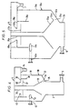
- the sewage treatment equipment can be seen to comprise a cylindrical primary settlement vessel 1 having an elongate sump 2, a lower outlet pipe 3 and an upper outlet pipe 4 which communicates directly with a cylindrical secondary settlement vessel 5.
- the secondary vessel 5 has a lower outlet pipe 6 and an upper overflow 7 for removal of cleaned effluent.
- the lower outlet pipe 6 of secondary vessel 5 communicates with a sludge well 8 (not fully shown in Figure 2 but shown separately in Figure 3) which has sludge outlet 9 and supernatant outlet 10.
- the primary vessel 1 is fed with sewage for treatment via conduit 11.
- the sewage is dosed with a coagulant at coagulant dosing device 12.
- Upstream of coagulant dosing device 12 is a header tank 13 which is fed by a pump (not shown) via inlet 14; header tank 13 communicates with the coagulant dosing device 12 via conduit 15.
- Primary settlement vessel 1 as shown is a low energy separator of the type described and illustrated in our British Patent No. 2082941; the secondary settlement vessel 5 as shown is a low energy separator, having provision for introduction of an energising fluid, as described and illustrated in our British Patent No. 2158741 (although it should be noted that the added energy ports are not in use in the apparatus shown).
- Solids accumulated at the base of separator 5 are periodically drawn off into sludge well 8, for instance by opening a valve controlled by handle 18.
- sewage for treatment is pumped to the header tank 13 via inlet 14.
- the sewage is fed via conduit 15 to dosing device 12 where the sewage is dosed with coagulant.
- the coagulant-dosed sewage is fed via conduit 11 to primary settlement vessel 1 where it is caused to flow in a rotational or circulating fashion.
- flocculation of fine solids suspended in the sewage is initiated.
- Some solids material, such as grit and large lumps of organic matter may settle under gravity into the elongate sump 2 at the base of the vessel 1 and this is removed by outlet pipe 3.
- the aqueous suspension of organic matter and substantially non-setteable flocs is passed via outlet pipe 4 to the secondary treatment vessel 5.
- the suspension is given a second chemical dose, this time with a flocculant, via a flocculant dosing device 19.
- the flocculant-dosed suspension is caused to circulate in vessel 4 and solids material settles under gravity under the flow patterns which prevail and which are described in our British Patent Specification No. 2082941, and is removed via outlet pipe 6 to sludge well 7. Clarified effluent is removed from an upper region of secondary vessel 5 via upper overflow 7.
- Sludge may be discharged from sludge well 8 via sludge outlet 9, whilst any supernatant may be removed via supernatant outlet 10.
- the internal structure of the primary separator 1 is shown in Figure 4.
- the separator comprises a cylindrical chamber 30 having an outer wall 31 and a base 32.
- a sump 2 is situated at the bottom of the vessel 1 to collect solid material separated out of the liquid mixture entering the vessel 1.
- Supported inside the chamber 30 is an inverted cone 33 which has a peripheral edge region 34 which, with the base 32, defines an annular gap 35.
- the cone 33 is supported by a column 36 which also supports a horizontal baffle plate 37.
- Projecting downwardly into the vessel is an annular dip plate 38.
- the top of the vessel is partially enclosed by a lid 39 having a central opening, the edge at the lid's inner periphery being upturned.
- Liquid is introduced into the vessel 1 via a tangential inlet 41 which is fed by pipe-line 42. Solids material may be removed from the sump via outlet 3 and the aqueous phase may be removed via outlet 14.
- the secondary treatment vessel 5 is structurally similar to the primary treatment vessel 1 and therefore like parts have been numbered with like reference numerals (but with the designation "a") except for the lower outlet 6 which is for discharging solid material accumulated at the base and the upper outlet 7 which is for discharging a classified aqueous phase.
- Secondary settlement vessel 5 includes an inlet 16 for introduction of an energising liquid to enhance rotational movement of liquid in the vessel 5 and ensure that solid matter does not accumulate at the base, but is swept inwards to the entrance to the outlet pipe 6 and thence to sludge well 8.
- Secondary vessel 5 also includes an outlet 17 for removal of liquid from the vessel, which removed liquid may then be energised by a pump (not shown) and returned to the vessel 4 as the energising liquid via inlet 16.
- This apparatus may also be operated without taking advantage of the possibility of introducing an energising liquid via inlet 16. Even if the added energy feature is employed, it should be noted that the operation of the device is still low energy in the sense that separation still occurs primarily under the influence of gravity.
- a liquid phase is introduced into the vessel via the tangential inlet 41 (41a) so as to create a low energy circulating flow of liquid in the vessel 1 (5).
- the internal arrangement of the components of the separator assists in establishing complex flow patterns in the vessel; a shear zone is stabilised between the lower peripheral edge of the cone 34 (34a) and the bottom edge of the dip plate 38 (38a).
- the complex flow patterns permit solid matter in the vessel to settle under gravity and cause this matter to be swept through the annular opening 35 (35a) to the sump 2 from whence it may be discharged via the lower outlet 3 (6).
- An aqueous phase passes between the gap between the horizontal baffle 37 (37a) and the dip plate 38 (38a) and from there into an upper region of the vessel 1 and out of the vessel via outlet 14 (7).
- the aqueous phase entering the primary treatment vessel is a raw sewage (from which grit and other gross solids may have been screened) which has been dosed with a coagulant.
- This dosing causes initiation of flocculation in the primary treatment vessel although in this vessel it is not intended that solids should settle and be collected. Any solids which do settle are those having a relatively high settling velocity and which sink immediately to the base and are swept to the sump 2.
- the majority of the solid material (for instance the colloidal material) in the aqueous sewage is carried out of the vessel via outlet 14 (7) and, from there, via inlet 41 (41a) into the secondary treatment vessel.
- the partially treated sewage from the primary vessel is dosed with a flocculant which causes rapid building of large flocs in the primary treatment vessel; these large flocs settle under gravity to the base 32a from where the are swept to the sump 2a for discharge.
- An aqueous phase passes out of the upper region of the vessel 5 via outlet 7. This aqueous phase is substantially free from any suspended solids and moreover has a very low bacterial level.
- the sewage treatment equipment illustrated in Figures 1 and 2 was used in tests to treat a sewage and evaluate its performance.
- the coagulant used was a ferric/alum/gypsum mix such as that commonly used in water treatment. This chemical was introduced into the sewage flow at the coagulant dosing device 12.
- the flocculant used was Zetag 92 made by Allied Colloids Limited. A dissolver was used to produce a solution of low viscosity and a concentration of 2500 mg/l was selected. Volumetric dosing rates in the range of 100 to 200 ml/minute were used into flocculant dosing device 15.
- the test was also run using alum containing 8% Al 2 O 3 .
- the plant was filled with sewage and a flow rate set. During the first hour of operation, dosing was initiated and after 11 ⁇ 2 to 2 hours a clarified effluent was taken from outlet 6 and analyzed for chemical and microbial content. The tests obtained are shown in the Table 1. It will be noted that the percentage removal of suspended solids and BOD is high whilst the removal of microbial content (total Coli, E.Coli and F. Streptomyces) is extremely high and this is evidence that the sewage treatment equipment in accordance with the present invention is capable of producing extremely clean effluent is suitable for discharge without further treatment for removal of solids and bacteria content.
Landscapes
- Chemical & Material Sciences (AREA)
- Chemical Kinetics & Catalysis (AREA)
- General Chemical & Material Sciences (AREA)
- Life Sciences & Earth Sciences (AREA)
- Hydrology & Water Resources (AREA)
- Engineering & Computer Science (AREA)
- Environmental & Geological Engineering (AREA)
- Water Supply & Treatment (AREA)
- Organic Chemistry (AREA)
- Separation Of Suspended Particles By Flocculating Agents (AREA)
- Polarising Elements (AREA)
Claims (22)
- Verfahren zur Behandlung einer Flüssigkeit, die suspendierte Feststoffe mitführt, umfassend folgende Schritte:(i) Einführen der Flüssigkeit in einen ersten Behandlungsbehälter und Veranlassen einer Agglomeration der in der Flüssigkeit suspendierten Feststoffe, so dass Flocken erhalten werden, die innerhalb der Zeit, welche man die Flüssigkeit im ersten Behälter belässt, sich nicht in erheblichem Umfang setzen;(ii) Überleiten eines wässrigen Bestandteils, der die Flocken aus dem ersten Behandlungsbehälter enthält, zu einer hydrodynamischen Trennvorrichtung, welche bewirkt, dass sich setzbare Flocken bilden; und(iii) Setzenlassen der Flocken in der hydrodynamischen Trennvorrichtung durch die Schwerkraft und Rückgewinnen eines wässrigen Bestandteils, der gegenüber der Ausgangsflüssigkeit einen wesentlich geringeren Gehalt an suspendierten Feststoffen enthält;wobei die Flüssigkeit im ersten Behälter Fließmustern unterworfen wird, umfassend einen Kreisfluss niedriger Energie um eine senkrechte Achse des ersten Behälters, so dass Bedingungen vorliegen für die Bildung von im wesentlichen nicht-setzenden Flocken - welche die Feststoffe enthalten, die in der Ausgangsflüssigkeit suspendiert waren - undwobei der wässrige Bestandteil aus dem ersten Behandlungsbehälter in der hydrodynamischen Trennvorrichtung unterworfen wird einem Kreisfluss niedriger Energie, welcher um eine senkrechte Achse der hydrodynamischen Trennvorrichtung kreist, so dass Bedingungen vorliegen für eine rasche Bildung von Flocken und für deren rasches Setzen im Anschluss daran,wobei der Fluss unterteilt wird in einen äußeren, vergleichsweise raschen Kreisfluss und in einen inneren, vergleichsweise langsamen Kreisfluss und zwischen diesen eine stabile Scherzone bestimmt wird.
- Verfahren nach Anspruch 1, wobei in Schritt (i) der erste Behandlungsbehälter der Behälter der hydrodynamischen Trennvorrichtung ist.
- Verfahren nach Anspruch 1 oder 2, wobei die Flüssigkeit mit den suspendierten Feststoffen im ersten Behandlungsbehälter mit einem Koagulierungsmittel versetzt wird - oder stromaufwärts davon - und dann die mit dem Koagulierungsmittel versehene Flüssigkeit im ersten Behandlungsbehälter einer Behandlung unterworfen wird.
- Verfahren nach Anspruch 3, wobei das im ersten Behandlungsbehälter verwendete Koagulierungsmittel ein anorganisches Koagulierungsmittel ist oder ein kationisches Polymer niedrigen Molekulargewichts (d. h., ein nicht-vernetztes Polymer).
- Verfahren nach Anspruch 4, wobei das anorganische Koagulierungsmittel ein Metallsalz ist.
- Verfahren nach Anspruch 5, wobei das Metallsalz ein Fe3+- oder ein Al3+-Salz ist.
- Verfahren nach Anspruch 6, wobei das Metallsalz ausgewählt ist aus Eisensulfat, Eisenchlorid, Alaun und Polyaluminiumchlorid.
- Verfahren nach Anspruch 4, wobei das niedermolekulare kationische Polymer ein Molekulargewicht von etwa 200,000 hat.
- Verfahren nach irgendeinem der Ansprüche 1 bis 8, wobei die Flockungsbedingungen im zweiten Behandlungsbehälter verstärkt werden, indem man dem wässrigen Bestandteil aus dem ersten Behandlungsbehälter ein Flockungsmittel zugibt.
- Verfahren nach Anspruch 9, wobei das Flockungsmittel ausgewählt ist aus der Klasse der organischen Polyelektrolyte, die in der Lage sind, Partikel miteinander zu verbrücken, so dass diese Partikel zu größeren Flocken zusammengebracht werden.
- Verfahren nach Anspruch 10, wobei das Flockungsmittel ein organischer Polyelektrolyt ist mit mittlerem bis hohem Molekulargewicht.
- Verfahren nach Anspruch 11, wobei der organische Polyelektrolyt ein durchschnittliches Molekulargewicht von mehr als 200.000 hat.
- Vorrichtung zur Behandlung einer Flüssigkeit, die suspendierte Feststoffe enthält, unter Verwendung des Verfahrens nach Anspruch 1, umfassend:(i) eine erste Behandlungsvorrichtung (1), in der die in der Flüssigkeit suspendierten Feststoffe zu einer Agglomeration unter Bildung von Flocken veranlasst werden, wobei die Behandlungsvorrichtung (1) beinhaltet: einen Behandlungsbehälter (30) mit einer Form, die es erlaubt, bei Gebrauch die Flüssigkeit in einen Kreisfluss niedriger Energie um eine senkrechte Achse des Behälters (30) zu bringen, wobei die Behandlungsvorrichtung (1) zudem ausgestattet ist mit einem Auslass (4) für ein Entfernen des wässrigen Bestandteils, der die Flocken aus dem Behälter (30) enthält; und(ii) eine zweite Behandlungsvorrichtung (5) in Form einer hydrodynamischen Trennvorrichtung;wobei der Auslass der ersten Behandlungsvorrichtung (4) mit dem Einlass (41) der hydrodynamischen Trennvorrichtung verbunden ist für ein Überleiten des wässrigen Bestandteils aus der ersten Behandlungsvorrichtung (4) in die hydrodynamische Trennvorrichtung (5),wobei die hydrodynamische Trennvorrichtung (5) so konstruiert ist, dass der wässrige Bestandteil einem Kreisfluss niedriger Energie um eine vertikale Achse der Vorrichtung unterworfen wird und der Fluss unterteilt wird in einen äußeren, rasch kreisenden Fluss und in einen inneren, langsam kreisenden Fluss, zwischen denen sich eine stabile Scherungszone ergibt.
- Vorrichtung nach Anspruch 13, wobei die erste Behandlungsvorrichtung (4) eine hydrodynamische Trennvorrichtung ist.
- Vorrichtung nach Anspruch 13 oder 14, wobei die oder alle hydrodynamischen Trennvorrichtungen umfassen:(a) einen Behälter (30, 30a) mit einer zylindrischen Außenwand (31, 31a) und einem Boden (32, 32a) an einem Ende;(b) einen Körper (33, 33a), der in dem Behälter (30, 30a) vorgesehen ist und der mit dem Boden (32, 32a) eine kreisförmige Öffnung (35, 35a) bestimmt, die von der Außenwand (31, 31a) beabstandet ist;(c) einen Einlass (41, 41a) zum Einführen einer Flüssigkeit, die suspendierte Feststoffe enthält, in den Behälter (30, 30a);(d) einen Auslass (14, 7) im oberen Bereich des Behälters (30, 30a) zum Entfernen einer wässrigen Phase aus dem Behälter (30, 30a);(e) eine kreisförmige Tauchplatte (38, 38a) im oberen Bereich des Behälters (30, 30a) und beabstandet von der äußeren Wand (31, 31a) des Behälters (30, 30a) zur Stabilisierung der Fließmuster im Behälter (30, 30a) ; und(f) Vorrichtungen zur Förderung eines Kreisflusses der Flüssigkeit und der suspendierten Feststoffe innerhalb des Behälters (30, 30a), wobei die Kreisbewegung hinreichend niederenergetisch ist, dass eine jegliche Abscheidung von Feststoffbestandteilen aus der Flüssigkeit im Behälter (30, 30a) hauptsächlich durch Schwerkraft erfolgt;wobei die Anordnung der Bauteile des Behälter (30, 30a) so ist, dass bei Gebrauch eine stabile Scherungszone in der kreisenden Flüssigkeit zwischen dem äußeren, vergleichsweise rasch kreisenden Bereich und dem inneren, vergleichsweise langsam kreisenden Bereich erhalten wird und eine nach innen gerichtete Wischwirkung erreicht wird für all die Feststoffe, die sich am Boden (32, 32a) des Behältere (30, 30a) angesammelt haben, hin zur kreisförmigen Öffnung (35, 35a).
- Vorrichtung nach Anspruch 13, 14 oder 15, die zudem eine Koagulierungsmittel-Dosiervorrichtung (12) aufweist, welche stromaufwärts des ersten Behandlungsbehälters (30) angeordnet ist.
- Vorrichtung nach Anspruch 16, wobei die Koagulierungsmittel-Dosiervorrichtung (12) eine Fließregulierung mit einem Vortexventil ist.
- Vorrichtung nach irgendeinem der Ansprüche 13 bis 16, die zudem eine Flockungsmittel-Dosiervorrichtung (19) aufweist, die zwischen der ersten und der zweiten Behandlungsvorrichtung (1, 5) geschaltet ist, damit man Flockungsmittel in die wässrige Phase zugeben kann.
- Vorrichtung zur Behandlung einer Flüssigkeit, die suspendierte Feststoffe enthält gemäß dem Verfahren nach Anspruch 1, umfassend erste und zweite verschaltete hydrodynamische Trennvorrichtungen (1, 5), wobei der Auslass (14) der ersten hydrodynamischen Trennvorrichtung (1), vorgesehen zum Entfernen einer im wesentlichen wässrigen Phase aus dem Behälter, in Verbindung steht mit dem Einlass (41) der zweiten hydrodynamischen Trennvorrichtung (5).
- Vorrichtung nach Anspruch 19, die zudem eine Koagulierungsmittel-Dosiervorrichtung (12) aufweist, angeordnet stromaufwärts der ersten hydrodynamischen Vorrichtung (1) .
- Vorrichtung nach Anspruch 20, wobei die Koagulierungsmittel-Dosiervorrichtung (12) eine Flussregulierung mit Vortexventil ist.
- Vorrichtung nach Anspruch 19, 20 oder 21, die zudem eine Flockungsmittel-Dosiervorrichtung (19) aufweist, geschaltet zwischen der ersten und der zweiten hydrodynamischen Trennvorrichtung (1, 5), damit man Flockungsmittel zur wässrigen Phase zugeben kann.
Applications Claiming Priority (5)
| Application Number | Priority Date | Filing Date | Title |
|---|---|---|---|
| GB9110733 | 1991-05-17 | ||
| GB919110733A GB9110733D0 (en) | 1991-05-17 | 1991-05-17 | Sewage treatment |
| GB9126941A GB2255725B (en) | 1991-05-17 | 1991-12-19 | Liquid treatment |
| GB9126941 | 1991-12-19 | ||
| PCT/GB1992/000894 WO1992020627A1 (en) | 1991-05-17 | 1992-05-18 | Liquid treatment |
Publications (2)
| Publication Number | Publication Date |
|---|---|
| EP0588820A1 EP0588820A1 (de) | 1994-03-30 |
| EP0588820B1 true EP0588820B1 (de) | 1997-08-13 |
Family
ID=26298919
Family Applications (1)
| Application Number | Title | Priority Date | Filing Date |
|---|---|---|---|
| EP92910379A Expired - Lifetime EP0588820B1 (de) | 1991-05-17 | 1992-05-18 | Aufbereitung von flüssigkeit |
Country Status (9)
| Country | Link |
|---|---|
| US (1) | US5480559A (de) |
| EP (1) | EP0588820B1 (de) |
| JP (1) | JPH06507573A (de) |
| AU (1) | AU1794792A (de) |
| CA (1) | CA2102813C (de) |
| DE (1) | DE69221617D1 (de) |
| IE (1) | IE921560A1 (de) |
| NZ (1) | NZ242779A (de) |
| WO (1) | WO1992020627A1 (de) |
Families Citing this family (15)
| Publication number | Priority date | Publication date | Assignee | Title |
|---|---|---|---|---|
| CA2212503C (en) * | 1997-08-07 | 1999-01-19 | William J. Kidd | Domestic water clarifier |
| GB9908634D0 (en) * | 1999-04-15 | 1999-06-09 | Hydro Int Ltd | Hydrodynamic vortex separator |
| US7153436B2 (en) * | 2003-02-13 | 2006-12-26 | Patrick W Bair | Method for enhancing cyclonic vessel efficiency with polymeric additives |
| WO2004087894A2 (en) * | 2003-04-01 | 2004-10-14 | S.C.Johnson & Son, Inc. | Bacterial aggregates |
| FR2856053B1 (fr) * | 2003-06-16 | 2005-11-18 | Rhodia Chimie Sa | Compositions a base de solutions stabilisees de polychlorure d'aluminium et de sel de fer pour le traitement d'effluents aqueux. |
| US20070221552A1 (en) * | 2004-05-18 | 2007-09-27 | Biomass Processing Technology, Inc. | System for Processing a Biomaterial Waste Stream |
| US8322540B2 (en) * | 2005-01-26 | 2012-12-04 | Royal Environmental Systems, Inc. | Filter element for water loaded with solid particles and dissolved toxic substances and purification system equipped with said filter element |
| US20060283788A1 (en) * | 2005-06-21 | 2006-12-21 | Schreppel Rudy Jr | Tri-clone system |
| US20060283805A1 (en) * | 2005-06-21 | 2006-12-21 | Schreppel Rudy Jr | Advanced separator system |
| US20070039894A1 (en) * | 2005-08-17 | 2007-02-22 | Cort Steven L | Water treatment using magnetic and other field separation technologies |
| FR2897610B1 (fr) * | 2006-02-20 | 2008-08-15 | Otv Sa | Installation et procede de traitement d'eau par floculation decantation a floc leste avec dessablage final des boues. |
| WO2008024445A2 (en) | 2006-08-23 | 2008-02-28 | Siemens Water Technologies Corp. | Sequencing batch reactor with continuous membrane filtration and solids reduction |
| US20080142447A1 (en) * | 2006-11-17 | 2008-06-19 | David Brian Mitchell | Method of treating wastewater |
| WO2018132306A1 (en) | 2017-01-10 | 2018-07-19 | Vermeer Manufacturing Company | Systems and methods for dosing slurries to remove suspended solids |
| JP7078527B2 (ja) * | 2018-12-18 | 2022-05-31 | 株式会社スギノマシン | 使用済研磨材分離システム |
Citations (1)
| Publication number | Priority date | Publication date | Assignee | Title |
|---|---|---|---|---|
| CA2006512A1 (en) * | 1989-11-15 | 1991-05-15 | Alban Timmons | Water treatment method |
Family Cites Families (15)
| Publication number | Priority date | Publication date | Assignee | Title |
|---|---|---|---|---|
| US2425065A (en) * | 1943-07-21 | 1947-08-05 | Dorr Co | Method of separating flocculatable and gritty solids from liquids |
| US3246762A (en) * | 1962-05-31 | 1966-04-19 | Sontheimer Heinrich | Apparatus for the treatment of contaminated liquid wastes by flocculation and clarification |
| GB1019035A (en) * | 1963-07-22 | 1966-02-02 | Head Wrightson & Co Ltd | Improvements relating to the treatment of suspensions of finely-divided solids in liquids |
| US3377274A (en) * | 1965-01-05 | 1968-04-09 | Nalco Chemical Co | Method of coagulation of low turbidity water |
| GB1153032A (en) * | 1965-07-07 | 1969-05-21 | Yorkshire Dyeware & Chem Co | Separation of Solid Particulate Material from Liquid Carriers by Settling |
| US3680698A (en) * | 1970-02-25 | 1972-08-01 | Occidental Petroleum Corp | Process for the treatment of slimes and waste solids |
| US3728253A (en) * | 1971-05-05 | 1973-04-17 | Univ California | Accelerated biological-chemical wastewater treatment |
| US4357242A (en) * | 1980-02-01 | 1982-11-02 | Chandler Associates, Inc. | Water purification method and apparatus |
| NZ197894A (en) * | 1980-08-11 | 1985-07-12 | Hydro Int Ltd | Vortex separator for sewage treatment;conical flow modifier in solids outlet |
| GB2158741B (en) * | 1984-05-14 | 1988-08-17 | Hydro Int Ltd | Separation of components of a fluid mixture |
| HUH3486A (en) * | 1989-02-03 | 1990-11-28 | Jozsef Vadasz | Method for phase decomposing manure mixtures consist of fecal and urine particularly oil/fat-bearing manure mixtures |
| NZ232508A (en) * | 1989-02-16 | 1993-03-26 | Golconda Eng & Mining | Clarifying liquid by adding flocculant and an inert particulate carrier |
| IL89685A (en) * | 1989-03-20 | 1993-04-04 | Odis Irrigation Equipment Ltd | Apparatus for treating a liquid mixture |
| US5124049A (en) * | 1991-02-28 | 1992-06-23 | Infilco Degremont Inc. | Liquid purification methods |
| GB9123566D0 (en) * | 1991-11-06 | 1992-01-02 | Clean Water Company The Limite | Improvements in or relating to separators |
-
1992
- 1992-05-18 EP EP92910379A patent/EP0588820B1/de not_active Expired - Lifetime
- 1992-05-18 WO PCT/GB1992/000894 patent/WO1992020627A1/en not_active Ceased
- 1992-05-18 CA CA002102813A patent/CA2102813C/en not_active Expired - Lifetime
- 1992-05-18 NZ NZ242779A patent/NZ242779A/en not_active IP Right Cessation
- 1992-05-18 AU AU17947/92A patent/AU1794792A/en not_active Abandoned
- 1992-05-18 US US08/146,159 patent/US5480559A/en not_active Expired - Lifetime
- 1992-05-18 JP JP4510489A patent/JPH06507573A/ja active Pending
- 1992-05-18 DE DE69221617T patent/DE69221617D1/de not_active Expired - Lifetime
- 1992-07-01 IE IE156092A patent/IE921560A1/en not_active Application Discontinuation
Patent Citations (1)
| Publication number | Priority date | Publication date | Assignee | Title |
|---|---|---|---|---|
| CA2006512A1 (en) * | 1989-11-15 | 1991-05-15 | Alban Timmons | Water treatment method |
Also Published As
| Publication number | Publication date |
|---|---|
| WO1992020627A1 (en) | 1992-11-26 |
| NZ242779A (en) | 1995-04-27 |
| CA2102813C (en) | 2003-10-14 |
| EP0588820A1 (de) | 1994-03-30 |
| IE921560A1 (en) | 1992-11-18 |
| AU1794792A (en) | 1992-12-30 |
| CA2102813A1 (en) | 1992-11-18 |
| JPH06507573A (ja) | 1994-09-01 |
| DE69221617D1 (de) | 1997-09-18 |
| US5480559A (en) | 1996-01-02 |
Similar Documents
| Publication | Publication Date | Title |
|---|---|---|
| EP0588820B1 (de) | Aufbereitung von flüssigkeit | |
| US4173532A (en) | Method for treating plant effluent | |
| Koohestanian et al. | The separation method for removing of colloidal particles from raw water | |
| Poon et al. | The use of ferric chloride and anionic polymer in the chemically assisted primary sedimentation process | |
| EP1330414B9 (de) | Verfahren zur behandlung von wasser und abwasser | |
| CA2266583C (en) | Water and wastewater treatment system with internal recirculation | |
| RU2523480C2 (ru) | Способ очистки воды | |
| US3846293A (en) | Liquid waste treatment | |
| US4293416A (en) | Apparatus for treating plant effluent | |
| AU2002220093A1 (en) | Method and apparatus for treatment of water and wastewater | |
| JPH03137988A (ja) | 六価クロムを水から除去する方法及び装置 | |
| US4882069A (en) | Method for the treatment of sewage and other impure water | |
| Menezes et al. | Removal of particles using coagulation and flocculation in a dynamic separator | |
| CN110228876A (zh) | 一种含煤废水处理系统及其方法 | |
| EP0062543A1 (de) | Verfahren und Vorrichtung zur physikalisch-chemischen Behandlung von Abfall | |
| US4076620A (en) | Process for the disposal of sewage | |
| Logsdon | Effective management and operation of coagulation and filtration | |
| GB2255725A (en) | Liquid treatment | |
| Burns et al. | Advanced or Tertiary Treatment | |
| KR101997143B1 (ko) | Ss와 svi 측정값을 이용한 가중응집제 실시간 제어 시스템 | |
| El-Bassuoni et al. | A novel compact coagulation-flocculation-sedimentation system | |
| Jokela et al. | Dissolved air flotation clarification of activated sludge and wastewaters from chemical industry | |
| Takhakh et al. | Treatment of Water by Direct Filtration | |
| Wiechers | Chemical phosphate removal from municipal waste waters: current practice and recent innovations | |
| Pizzi | Water Treatment Plant Residuals Field Guide |
Legal Events
| Date | Code | Title | Description |
|---|---|---|---|
| PUAI | Public reference made under article 153(3) epc to a published international application that has entered the european phase |
Free format text: ORIGINAL CODE: 0009012 |
|
| 17P | Request for examination filed |
Effective date: 19931215 |
|
| AK | Designated contracting states |
Kind code of ref document: A1 Designated state(s): BE DE DK ES FR GB GR IT NL SE |
|
| 17Q | First examination report despatched |
Effective date: 19950424 |
|
| GRAG | Despatch of communication of intention to grant |
Free format text: ORIGINAL CODE: EPIDOS AGRA |
|
| GRAH | Despatch of communication of intention to grant a patent |
Free format text: ORIGINAL CODE: EPIDOS IGRA |
|
| GRAH | Despatch of communication of intention to grant a patent |
Free format text: ORIGINAL CODE: EPIDOS IGRA |
|
| RAP1 | Party data changed (applicant data changed or rights of an application transferred) |
Owner name: HYDRO INTERNATIONAL PLC. |
|
| RBV | Designated contracting states (corrected) |
Designated state(s): BE DE DK ES FR GR IT NL SE |
|
| GRAA | (expected) grant |
Free format text: ORIGINAL CODE: 0009210 |
|
| AK | Designated contracting states |
Kind code of ref document: B1 Designated state(s): BE DE DK ES FR GR IT NL SE |
|
| PG25 | Lapsed in a contracting state [announced via postgrant information from national office to epo] |
Ref country code: NL Free format text: LAPSE BECAUSE OF FAILURE TO SUBMIT A TRANSLATION OF THE DESCRIPTION OR TO PAY THE FEE WITHIN THE PRESCRIBED TIME-LIMIT Effective date: 19970813 Ref country code: IT Free format text: LAPSE BECAUSE OF FAILURE TO SUBMIT A TRANSLATION OF THE DESCRIPTION OR TO PAY THE FEE WITHIN THE PRE;WARNING: LAPSES OF ITALIAN PATENTS WITH EFFECTIVE DATE BEFORE 2007 MAY HAVE OCCURRED AT ANY TIME BEFORE 2007. THE CORRECT EFFECTIVE DATE MAY BE DIFFERENT FROM THE ONE RECORDED.SCRIBED TIME-LIMIT Effective date: 19970813 Ref country code: GR Free format text: LAPSE BECAUSE OF FAILURE TO SUBMIT A TRANSLATION OF THE DESCRIPTION OR TO PAY THE FEE WITHIN THE PRESCRIBED TIME-LIMIT Effective date: 19970813 Ref country code: FR Free format text: LAPSE BECAUSE OF FAILURE TO SUBMIT A TRANSLATION OF THE DESCRIPTION OR TO PAY THE FEE WITHIN THE PRESCRIBED TIME-LIMIT Effective date: 19970813 Ref country code: ES Free format text: THE PATENT HAS BEEN ANNULLED BY A DECISION OF A NATIONAL AUTHORITY Effective date: 19970813 Ref country code: DK Free format text: LAPSE BECAUSE OF NON-PAYMENT OF DUE FEES Effective date: 19970813 Ref country code: BE Effective date: 19970813 |
|
| REF | Corresponds to: |
Ref document number: 69221617 Country of ref document: DE Date of ref document: 19970918 |
|
| PG25 | Lapsed in a contracting state [announced via postgrant information from national office to epo] |
Ref country code: SE Effective date: 19971113 |
|
| PG25 | Lapsed in a contracting state [announced via postgrant information from national office to epo] |
Ref country code: DE Effective date: 19971114 |
|
| EN | Fr: translation not filed | ||
| NLV1 | Nl: lapsed or annulled due to failure to fulfill the requirements of art. 29p and 29m of the patents act | ||
| PLBE | No opposition filed within time limit |
Free format text: ORIGINAL CODE: 0009261 |
|
| STAA | Information on the status of an ep patent application or granted ep patent |
Free format text: STATUS: NO OPPOSITION FILED WITHIN TIME LIMIT |
|
| 26N | No opposition filed |