EP0589097B1 - Leitschwellenelement - Google Patents
Leitschwellenelement Download PDFInfo
- Publication number
- EP0589097B1 EP0589097B1 EP19920202994 EP92202994A EP0589097B1 EP 0589097 B1 EP0589097 B1 EP 0589097B1 EP 19920202994 EP19920202994 EP 19920202994 EP 92202994 A EP92202994 A EP 92202994A EP 0589097 B1 EP0589097 B1 EP 0589097B1
- Authority
- EP
- European Patent Office
- Prior art keywords
- guide rail
- rail section
- hatch
- wall
- assembly
- Prior art date
- Legal status (The legal status is an assumption and is not a legal conclusion. Google has not performed a legal analysis and makes no representation as to the accuracy of the status listed.)
- Expired - Lifetime
Links
Images
Classifications
-
- E—FIXED CONSTRUCTIONS
- E01—CONSTRUCTION OF ROADS, RAILWAYS, OR BRIDGES
- E01F—ADDITIONAL WORK, SUCH AS EQUIPPING ROADS OR THE CONSTRUCTION OF PLATFORMS, HELICOPTER LANDING STAGES, SIGNS, SNOW FENCES, OR THE LIKE
- E01F15/00—Safety arrangements for slowing, redirecting or stopping errant vehicles, e.g. guard posts or bollards; Arrangements for reducing damage to roadside structures due to vehicular impact
- E01F15/02—Continuous barriers extending along roads or between traffic lanes
- E01F15/08—Continuous barriers extending along roads or between traffic lanes essentially made of walls or wall-like elements ; Cable-linked blocks
- E01F15/081—Continuous barriers extending along roads or between traffic lanes essentially made of walls or wall-like elements ; Cable-linked blocks characterised by the use of a specific material
- E01F15/085—Continuous barriers extending along roads or between traffic lanes essentially made of walls or wall-like elements ; Cable-linked blocks characterised by the use of a specific material using metal
Definitions
- the invention relates to a guide rail section for partitioning part of a roadway, provided with a foot and side walls adjoining the foot, wherein at one extremity of the guide rail section the foot and/or the side walls can be coupled to the respective foot or side walls of a similar guide rail section and wherein at least one wall of the guide rail is provided with a hole and a detachable assembly hatch fitting in it near the extremity.
- Such a guide rail section is known from practice and is used for composing a guide rail of it by coupling several guide rail sections together.
- Guide rail sections are manufactured in a factory and then transported to the desired place of erection. In this place the guide rail sections must be easy to couple in order to make the roadway on the spot available for traffic again as soon as possible.
- the intercoupling of guide rail sections takes place with strips of sheet metal which are laid longitudinally over the extremities of two guide rail sections adjoining each other and are fastened to the guide rail sections with bolts and nuts and/or rivets.
- an assembly hatch is fitted near the extremity of a guide rail section.
- the known assembly hatch has a rectangular shape and is fastened to the guide rail section by means of a number of bolts. On a guide rail strength requirements are imposed both as to longitudinal and transverse load. The assembly hatch must not reduce the strength properties of the guide rail to beneath the minimum strength requirements.
- a drawback of the known assembly hatch is that fitting of it after guide rail sections have been coupled together requires much time. It is strived for to have a day or night shift install at least thousand metres of guide rail sections. The necessity of fitting the assembly hatch constitutes a limitation of the amount of guide rail that can be installed per shift.
- An object of the invention is to provide a guide rail section with which the above-mentioned problems are eliminated or reduced to a considerable extent and with which other added advantages are achieved.
- a guide rail section in accordance with the invention is characterized in that the assembly hatch is provided with at least a twist-lock fastening for the clamping of it in the wall.
- the twist-lock fastening enables quick fitting of the assembly hatch; the design of the construction can be so sturdy that the twist-lock fastening is still detachable without a problem after long exposure to the outside climate.
- a further embodiment of the invention suitable for application with a great variety of shapes of the assembly hatch is characterized in that the twist-lock fastening comprises an arm fastened on the hatch which arm is suitable for being brought into locking contact with the inward part of the wall.
- An embodiment of the invention in which the assembly hatch can be fitted very quickly is characterized in that the assembly hatch is an essentially circular plate and that the inward part of the wall is provided with a clamping plate on which the arm can be brought into locking contact.
- This embodiment has the added advantage that less concentration of stress occurs around the hole in which the assembly hatch fits due to which the mechanical strength of the guide rail section is influenced less disadvantageously.
- a further embodiment of the invention is characterized in that the clamping plate is fastened at a distance from the wall.
- a further embodiment of the invention is characterized in that the assembly hatch is provided with means for turning the assembly hatch around its centre.
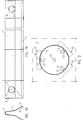
- reference number (1) represents a guide rail section.
- Guide rail section (1) has a foot (2) and side walls (3).
- side wall (3) is provided with a round hole (4) in which an assembly hatch (5) is fitted.
- assembly hatch (5) is fitted at the extremity near assembly hatch (5) a composite flange (6) is fastened by means of a number of rivets (7).
- the other extremity of the guide rail section can be provided with a second hole (8) and an assembly hatch (9) fitting in it.
- Fig. 1B shows a front view of a guide rail section. At one extremity the guide rail section is provided with a composite flange (6) which runs across practically the entire inner wall of the guide rail section. This flange (6) is to be connected to the extremity of a similar guide rail section by means of bolts.
- Fig. 2 shows part of a guide rail section with the hole (4) and the assembly hatch (5) fitted in it.
- the round assembly hatch (5) is provided with arms (11) which are fastened rigidly to the assembly hatch (5).
- clamping plates (12) are fitted at a distance from the wall. In the drawn situation the parts (13) of the arms (11) lie under the clamping plates (12), viewed in the drawn situation, and are in locking contact with the clamping plates (12).
- the strip (14) is a stop for limiting the angle of rotation of the assembly hatch.
- Reference number (15) indicates a central hole in the assembly hatch in which an appropriate tool fits to enable rotation and with that fastening or detachment of the assembly hatch.
Landscapes
- Engineering & Computer Science (AREA)
- Architecture (AREA)
- Civil Engineering (AREA)
- Structural Engineering (AREA)
- Connection Of Plates (AREA)
- Support Devices For Sliding Doors (AREA)
Claims (5)
- Führungsschienenabschnitt (1) zum Abtrennen eines Teils einer Fahrbahn mit einem Fuß (2) und an den Fuß anschließenden Seitenwänden (3), wobei an einem Ende des Führungsschienenabschnittes der Fuß und/oder die Seitenwände mit jeweils dem Fuß oder den Seitenwänden eines ähnlichen Führungsschienenabschnitts gekuppelt werden kann, und wobei wenigstens eine Wand der Führungsschiene nahe des Endes mit einer öffnung (4, 8) und einem in sie eingesetzten lösbaren Montagedeckel (5, 9) versehen ist,
dadurch gekennzeichnet,
daß der Montagedeckel mit wenigstens einer Twistlock-Befestigungsvorrichtung versehen ist, um ihn in der Wand festzuklemmen. - Führungsschienenabschnitt nach Anspruch 1,
dadurch gekennzeichnet,
daß die Twistlock-Befestigungsvorrichtung einen an dem Deckel befestigten Arm (11) aufweist, welcher Arm geeignet ist, in Verriegelungskontakt mit dem innenliegenden Teil der Wand gebracht zu werden. - Führungsschienenabschnitt nach Anspruch 2,
dadurch gekennzeichnet,
daß der Montagedeckel eine im wesentlichen kreisförmige Platte ist und daß der innenliegende Teil der Wand mit einer Klemmplatte (12) versehen ist, an der der Arm in Verriegelungskontakt gebracht wird. - Führungsschiene nach Anspruch 3,
dadurch gekennzeichnet,
daß die Klemmplatte mit einem Abstand von der Wand befestigt ist. - Führungsschiene nach Anspruch 3 oder 4,
dadurch gekennzeichnet,
daß der Montagedeckel mit Mitteln (15) versehen ist, um den Montagedeckel um seine Mitte zu drehen.
Priority Applications (1)
| Application Number | Priority Date | Filing Date | Title |
|---|---|---|---|
| EP19920202994 EP0589097B1 (de) | 1992-09-15 | 1992-09-30 | Leitschwellenelement |
Applications Claiming Priority (3)
| Application Number | Priority Date | Filing Date | Title |
|---|---|---|---|
| EP92202825 | 1992-09-15 | ||
| EP92202825 | 1992-09-15 | ||
| EP19920202994 EP0589097B1 (de) | 1992-09-15 | 1992-09-30 | Leitschwellenelement |
Publications (2)
| Publication Number | Publication Date |
|---|---|
| EP0589097A1 EP0589097A1 (de) | 1994-03-30 |
| EP0589097B1 true EP0589097B1 (de) | 1996-04-24 |
Family
ID=26131696
Family Applications (1)
| Application Number | Title | Priority Date | Filing Date |
|---|---|---|---|
| EP19920202994 Expired - Lifetime EP0589097B1 (de) | 1992-09-15 | 1992-09-30 | Leitschwellenelement |
Country Status (1)
| Country | Link |
|---|---|
| EP (1) | EP0589097B1 (de) |
Families Citing this family (1)
| Publication number | Priority date | Publication date | Assignee | Title |
|---|---|---|---|---|
| DE10144276A1 (de) * | 2001-09-08 | 2003-03-27 | Georg Hipp | Fahrbahnbegrenzungsvorrichtung |
Family Cites Families (2)
| Publication number | Priority date | Publication date | Assignee | Title |
|---|---|---|---|---|
| DE8700353U1 (de) * | 1987-01-08 | 1987-03-19 | SPS Schutzplanken GmbH, 8750 Aschaffenburg | Schutzplankeneinrichtung, bestehend aus als Fertigteile aus Stahlplatten hergestellten Einzelteilen |
| DE59002337D1 (de) * | 1990-06-21 | 1993-09-16 | Spig Schutzplanken Prod Gmbh | Schutzplankenstrang. |
-
1992
- 1992-09-30 EP EP19920202994 patent/EP0589097B1/de not_active Expired - Lifetime
Also Published As
| Publication number | Publication date |
|---|---|
| EP0589097A1 (de) | 1994-03-30 |
Similar Documents
| Publication | Publication Date | Title |
|---|---|---|
| EP0039251A2 (de) | Isolierende Verbundmauer | |
| US4427173A (en) | Self-leveling sleeve insert for concrete passages | |
| US8069519B2 (en) | Bridge decking panel with fastening systems and method for casting the decking panel | |
| DE20007477U1 (de) | Montagesystem für Durchführungen durch Trapezblechdecken | |
| US5167474A (en) | Form for making a permanent concrete mine stopping | |
| EP1031669B1 (de) | Gebäuderahmen mit Sigma-Profilen | |
| EP0208651A1 (de) | Gerippe für domförmige Dächer | |
| US6279281B1 (en) | Concrete forming system | |
| EP0589097A1 (de) | Leitschwellenelement | |
| US4624086A (en) | Adjustable self-leveling sleeve insert for concrete passages | |
| US4238913A (en) | Bulkhead structure | |
| KR102516513B1 (ko) | 교량용 지지대 일체형 캔틸레버 구조물 및 그 시공방법 | |
| US4253605A (en) | Railway crossing structure | |
| GB2027785A (en) | A Connection Between a Beam or Beams and a Pillar, all of Prefabricated Concrete | |
| US826904A (en) | Building-sheating means. | |
| CN214995076U (zh) | 用于房屋建筑中地下车库的防裂顶板结构 | |
| SG11202112605RA (en) | Prefabricated wall | |
| GB2109843A (en) | Frame members for supporting covers or gratings | |
| JPS6340586Y2 (de) | ||
| DE2363112A1 (de) | Stahlbetontraeger, insbesondere fuer herstellung von flachdaechern und decken | |
| JP4255175B2 (ja) | 母屋の取付け構造 | |
| DE2015905A1 (de) | Patentwesen, Ost-Berlin WP139730 Wärmebeständiges Leichtbauelement für Aus- und Verkleidung von Wärmeanlagen, insbesondere Industrieöfen, Trockenkammern, Rauchgaskanälen und Dampferzeugern | |
| EP0385998B1 (de) | Bodenstruktur für gebäude | |
| DE102019119417A1 (de) | Schalungselement | |
| CN212863692U (zh) | 一种施工升降机位于建筑物夹缝的附着结构 |
Legal Events
| Date | Code | Title | Description |
|---|---|---|---|
| PUAI | Public reference made under article 153(3) epc to a published international application that has entered the european phase |
Free format text: ORIGINAL CODE: 0009012 |
|
| 17P | Request for examination filed |
Effective date: 19920930 |
|
| AK | Designated contracting states |
Kind code of ref document: A1 Designated state(s): BE DE GB NL |
|
| 17Q | First examination report despatched |
Effective date: 19951013 |
|
| GRAA | (expected) grant |
Free format text: ORIGINAL CODE: 0009210 |
|
| AK | Designated contracting states |
Kind code of ref document: B1 Designated state(s): BE DE GB NL |
|
| RAP2 | Party data changed (patent owner data changed or rights of a patent transferred) |
Owner name: LAURA METAAL EYGELSHOVEN BV |
|
| REF | Corresponds to: |
Ref document number: 69210238 Country of ref document: DE Date of ref document: 19960530 |
|
| NLT2 | Nl: modifications (of names), taken from the european patent patent bulletin |
Owner name: LAURA METAAL EYGELSHOVEN BV |
|
| PLBE | No opposition filed within time limit |
Free format text: ORIGINAL CODE: 0009261 |
|
| 26N | No opposition filed | ||
| REG | Reference to a national code |
Ref country code: GB Ref legal event code: IF02 |
|
| PGFP | Annual fee paid to national office [announced via postgrant information from national office to epo] |
Ref country code: GB Payment date: 20040817 Year of fee payment: 13 |
|
| PGFP | Annual fee paid to national office [announced via postgrant information from national office to epo] |
Ref country code: DE Payment date: 20040818 Year of fee payment: 13 |
|
| PGFP | Annual fee paid to national office [announced via postgrant information from national office to epo] |
Ref country code: NL Payment date: 20040909 Year of fee payment: 13 |
|
| PGFP | Annual fee paid to national office [announced via postgrant information from national office to epo] |
Ref country code: BE Payment date: 20040916 Year of fee payment: 13 |
|
| PG25 | Lapsed in a contracting state [announced via postgrant information from national office to epo] |
Ref country code: GB Free format text: LAPSE BECAUSE OF NON-PAYMENT OF DUE FEES Effective date: 20050930 Ref country code: BE Free format text: LAPSE BECAUSE OF NON-PAYMENT OF DUE FEES Effective date: 20050930 |
|
| PG25 | Lapsed in a contracting state [announced via postgrant information from national office to epo] |
Ref country code: NL Free format text: LAPSE BECAUSE OF NON-PAYMENT OF DUE FEES Effective date: 20060401 Ref country code: DE Free format text: LAPSE BECAUSE OF NON-PAYMENT OF DUE FEES Effective date: 20060401 |
|
| GBPC | Gb: european patent ceased through non-payment of renewal fee |
Effective date: 20050930 |
|
| NLV4 | Nl: lapsed or anulled due to non-payment of the annual fee |
Effective date: 20060401 |
|
| BERE | Be: lapsed |
Owner name: *LAURA METAAL EYGELSHOVEN B.V. Effective date: 20050930 |