EP0589202B1 - Elektrostatische Pulverbeschichtungspistole und Verfahren zum Erzeugen einer Hochspannung - Google Patents
Elektrostatische Pulverbeschichtungspistole und Verfahren zum Erzeugen einer Hochspannung Download PDFInfo
- Publication number
- EP0589202B1 EP0589202B1 EP93113098A EP93113098A EP0589202B1 EP 0589202 B1 EP0589202 B1 EP 0589202B1 EP 93113098 A EP93113098 A EP 93113098A EP 93113098 A EP93113098 A EP 93113098A EP 0589202 B1 EP0589202 B1 EP 0589202B1
- Authority
- EP
- European Patent Office
- Prior art keywords
- voltage
- frequency
- transformer
- output
- primary coil
- Prior art date
- Legal status (The legal status is an assumption and is not a legal conclusion. Google has not performed a legal analysis and makes no representation as to the accuracy of the status listed.)
- Expired - Lifetime
Links
Images


Classifications
-
- B—PERFORMING OPERATIONS; TRANSPORTING
- B05—SPRAYING OR ATOMISING IN GENERAL; APPLYING FLUENT MATERIALS TO SURFACES, IN GENERAL
- B05B—SPRAYING APPARATUS; ATOMISING APPARATUS; NOZZLES
- B05B5/00—Electrostatic spraying apparatus; Spraying apparatus with means for charging the spray electrically; Apparatus for spraying liquids or other fluent materials by other electric means
- B05B5/025—Discharge apparatus, e.g. electrostatic spray guns
- B05B5/053—Arrangements for supplying power, e.g. charging power
- B05B5/0531—Power generators
-
- H—ELECTRICITY
- H02—GENERATION; CONVERSION OR DISTRIBUTION OF ELECTRIC POWER
- H02M—APPARATUS FOR CONVERSION BETWEEN AC AND AC, BETWEEN AC AND DC, OR BETWEEN DC AND DC, AND FOR USE WITH MAINS OR SIMILAR POWER SUPPLY SYSTEMS; CONVERSION OF DC OR AC INPUT POWER INTO SURGE OUTPUT POWER; CONTROL OR REGULATION THEREOF
- H02M3/00—Conversion of DC power input into DC power output
- H02M3/22—Conversion of DC power input into DC power output with intermediate conversion into AC
- H02M3/24—Conversion of DC power input into DC power output with intermediate conversion into AC by static converters
- H02M3/28—Conversion of DC power input into DC power output with intermediate conversion into AC by static converters using discharge tubes with control electrode or semiconductor devices with control electrode to produce the intermediate AC
- H02M3/325—Conversion of DC power input into DC power output with intermediate conversion into AC by static converters using discharge tubes with control electrode or semiconductor devices with control electrode to produce the intermediate AC using devices of a triode or a transistor type requiring continuous application of a control signal
- H02M3/335—Conversion of DC power input into DC power output with intermediate conversion into AC by static converters using discharge tubes with control electrode or semiconductor devices with control electrode to produce the intermediate AC using devices of a triode or a transistor type requiring continuous application of a control signal using semiconductor devices only
- H02M3/33507—Conversion of DC power input into DC power output with intermediate conversion into AC by static converters using discharge tubes with control electrode or semiconductor devices with control electrode to produce the intermediate AC using devices of a triode or a transistor type requiring continuous application of a control signal using semiconductor devices only with automatic control of the output voltage or current, e.g. flyback converters
Definitions
- the invention relates to a method for generating a high voltage in an electrostatic powder coating gun according to the preamble of claim 1 and a corresponding electrostatic powder coating gun.
- a process of type mentioned is z. B. in WO-A-90/07381, from which is basically known the frequency of the supply voltage towards the resonant frequency of the transformer regulate.
- a similar control device is the subject of FR-A-2 618 618.
- Known powder coating devices generally have one High voltage generator, one transformer and one Has transformer downstream high-voltage cascade.
- the Output voltage of the transformer becomes the low voltage input the high voltage cascade and the output voltage of the high voltage cascade a high voltage coating electrode fed.
- the primary coil of the transformer is in operation of the coating device by one with an operating frequency operated supply AC voltage.
- normally Power supply provided with a supply AC voltage one tailored to the components of the high-voltage generator Outputs operating frequency, the high-voltage transformer the frequency-determining part of this so-called “Self-oscillating oscillator” forms.
- Operation of the high voltage generator depends on its individual components, such as transformer, high-voltage cascade, etc., as well as inductive and capacitive influences, such as length, Cross section and type of cable or due to external interference arise.
- the described oscillators known from the prior art have to settle to the working frequency when the coating device is switched on and should keep this working frequency as possible during operation.
- the operating frequency of the high-voltage generator largely determines the primary coil current of the transformer.
- the high-voltage generator should be operated at such a frequency as possible, at which the primary coil current is minimal and the efficiency of the high-voltage generator is therefore maximal.
- This primary coil current minimum is very pronounced, for example, in the case of the chamber coils frequently used in such high-voltage generators.
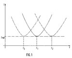
- 1 shows a diagram of the primary coil current I as a function of the frequency F of the supply voltage, with three operating points f 1 , f 2 and f 3 being shown to explain these relationships.
- the various operating points at which the primary coil minimum I min lies essentially depend on the system design. If the frequency of the supply voltage for a high-voltage generator deviates from the operating point in a positive or negative direction due to the system load or external interference, the primary coil current increases.
- the high voltage generator can a fixed power supply, fixed cable lengths and a given transformer and high voltage cascade for a given constant Load, i.e. for a working point at which the working frequency, the primary coil current and the high voltage remain constant, however, if the damping of the so formed oscillating circuit by different load currents changes, this system can change conditions not be adjusted accordingly. This leads to a change Current consumption of the high voltage generator and has to As a result, the desired output voltage is not maintained can become and the efficiency drops significantly. Very high Burdens can go up to a short-term, complete Breakdown of the output high voltage. Also affect the tolerances of AC and DC gain factors of oscillator transistors and supply cables Behavior of the entire resonant circuit. It also has been in practice shown that such oscillators with longer cable lengths lose a lot of power or stop swinging.
- the invention is therefore based on the object of a powder coating gun with high voltage generator and a process for generating a high voltage in a powder coating gun to create a constant oscillation circuit with them for the high voltage is achieved.
- the high voltage generator regardless of loads, disturbances and Fluctuations in the inductive and capacitive sizes of the system deliver a constant, maximum high voltage.
- this object is achieved by a method Claim 1 and an electrostatic powder coating gun solved according to claim 7.
- the high voltage generator and the process for high voltage generation according to the invention form a so-called "self-optimizing active resonance system ".
- the high voltage generator is operated with an alternating voltage, the frequency of which is continuous enlarged and reduced over a limited area (wobbled).
- the primary coil current becomes continuous measured and the increase or decrease of the primary coil current is measured detected. If the current drops, the wobble direction maintained, the current increases so the wobble direction changed. In this way you get an indirect adjustment the working frequency to the coil properties.
- the resonant circuit and thus the one emitted by the high voltage generator Voltage is largely independent of the system components, like the transformer and the supply cables, because the Transformer is no longer a frequency-determining part of the Resonant circuit is.
- the optimal working frequency is achieved with the help of the primary coil current determined, and by wobbling the frequency of the Supply voltage and shifting the wobble area dependent from the primary coil current, and thus depending on the current one Load, this frequency is adjusted so that the high voltage generator essentially always in the area of the primary coil current minimum is operated.
- Fig. 2 is a high voltage generator with a transformer 10 and a high-voltage cascade connected downstream of the transformer 12 shown.
- the primary coil 14 of the transformer 10 is operated via a push-pull amplifier operated as an end switching stage 16 and with a downstream output capacitor 18, for example an electrolytic capacitor.
- the push-pull amplifier 16 is a wobble generator 20 connected upstream of a voltage controlled oscillator (VCO) 22 and a dead time control element 24.
- VCO voltage controlled oscillator
- the primary coil 14 of the transformer 10 is via a current measuring resistor 26 grounded.
- the voltage proportional to the current a current measuring circuit 28 is fed to the current measuring resistor 26, in which a peak value rectifier 30, a differentiator 32 and a first order delay element (PT-1) 34 in Series are connected.
- the output signal of this current measuring circuit 28 is connected to an input E2 of an AND gate 36 other input E1 of the AND gate 36 is with an oscillator 38 connected, which can output a square wave.
- the output signal of the AND gate 36 is connected to a control device 40 to control the wobble generator 20.
- the control device 40 has a clock-edge-controlled JK memory element or JK flip-flop 42, whose non-inverted Output via an integrator 44 with the input of the wobble generator 20 is connected, the output INT of the integrator 44 via two parallel comparators 46 and 48 to the setting input S or returned to the reset input R of the JK flip-flop 42 is.
- the clock input of the JK flip-flop 42 is included connected to the output of the AND gate 36. At the J entrance and at the K entrance of the JK flip-flop 42 there is always a logic "1", so that the JK flip-flop works like a T flip-flop; i.e.
- the operation of the circuit shown is with reference below described on Fig. 3.
- the current measuring circuit 28 continuously the Primary coil current proportional voltage at the current measuring resistor 26 added. This voltage is rectified by the rectifier 30, differentiated in the differentiator 32 and from the following PT1 link 34 smoothed.
- At the output (E2) of the PT1 link becomes a logical with increasing primary coil current "1" signal and a logical one when the primary coil current falls 0 "signal formed.
- the current measuring circuit accordingly detects changes of the primary coil current and converts them into logic signals ("1": rising; "0”: falling). It is therefore also as Designated comparator 28.
- the output signal E2 of the current measuring circuit is from the AND gate 36 with the output signal E1 (input clock) of the oscillator 38 linked.
- the instantaneous operating frequency of the oscillator is relatively far from the optimum, ie the primary coil current I is significantly greater than I min .
- the coil current briefly reaches the coil current minimum, and in the subsequent interval t 1 ⁇ t 3 , the coil current increases again, and the comparator output E2 goes to "1".
- the AND operation of E1 (input clock) and E2 changes the polarity of the JK flip-flop output Q only with the next rising edge of E1, and the wobble direction is only switched at time t 2 .
- the integrator 44 With the change in polarity of Q, the integrator 44 also changes its direction of integration, which, as will be described in more detail, results in the change in the wobble direction.
- the time interval t 2 ⁇ t 3 includes, in particular, the delay caused by the PT1 element and the further delays caused by the overall system.
- the total delay time is designated ⁇ t s .
- the primary coil current I therefore only drops again at time t 3, again reaches the coil current minimum at time t 4 , and the process described above is repeated.
- the primary coil current is reproduced in a greatly expanded time.
- the system delay time is much smaller than the period of the clock generator 38, ie ⁇ t s ⁇ T.
- the reaction time from recognizing the coil current rise to switching the wobble direction is not constant and can be a maximum of half a period T / 2 of the clock generator 38 (t 1 ⁇ t 2 or t 4 ⁇ t 5 ).
- the output voltage INT of the integrator 44 is used for control of the voltage controlled oscillator 22.
- This is at Embodiment shown a VCO, the a rectangular supply voltage with depending on the amplitude of the integrator output voltage modulated pulse length for the transformer 10 of the high voltage generator supplies.
- the ramp rising and falling integrator output voltage INT causes in practice a modulation of the oscillator output frequency of approximately +/- 90 Hz at an operating frequency of approximately 19-30 kHz.
- the dead time control element connected downstream of the oscillator 22 24 delays the output signal of the oscillator 22, see above that error-free control of the output stage transistors Push-pull output stage 16 is ensured.
- the output voltage of the integrator has a first reference value Ref.1 falls below or a second reference value Ref.2 this is recognized by the comparators 46 and 48, and the JK flip-flop is at a defined initial state put on or reset.
- the signals SET and RESET have so higher priority and force the wobble direction in the correct direction. This ensures that the output voltage of the voltage controlled oscillator within a certain predetermined frequency range, for example between 10 kHz and 90 kHz, remains. This is necessary because the Oscillating circuit otherwise at resonance frequencies outside this range the downstream high voltage generator (the can simply be described as a PT2 element) uncontrolled could swing up.
- the input oscillator 38 also ensures when switched on of the system that the output signal INT of the integrator 44 approximately in the middle of the work area.
- the working frequency of the high voltage generator in one Range from 15 to 30 kHz, preferably at 19 to 27 kHz.
- This Working frequency is with a modulation or wobble frequency on the order of 100 Hz around +/- 90 Hz around the operating point changed around.
Landscapes
- Engineering & Computer Science (AREA)
- Power Engineering (AREA)
- Electrostatic Spraying Apparatus (AREA)
- Generation Of Surge Voltage And Current (AREA)
Description
- Fig. 1
- ein Diagramm des Primärspulenstroms abhängig von der Frequenz der Versorgungsspannung,
- Fig. 2
- einen Schaltplan gemäß einer Ausführungsform der Erfindung und
- Fig. 3
- den zeitlichen Verlauf von Signalen der Schlatung von Fig. 3.
Claims (11)
- Verfahren zum Erzeugen einer frequenzarmen Hochspannung in einer elektrostatischen Pulverbeschichtungspistole mit einem Hochspannungserzeuger, der einen Transformator und eine dem Transformator (10) nachgeschaltete Hochspannungskaskade (12) aufweist, bei dem die Ausgangsspannung des Transformators (10) dem Niederspannungseingang der Hochspannungskaskade (12) und die Ausgangsspannung der Hochspannungskaskade einer Beschichtungs-Hochspannungselektrode zugeführt werden, die Primärspule (14) des Transformators durch eine mit einer Arbeitsfrequenz betriebene Versorgungs-Wechselspannung gespeist wird und während des Betriebs der Beschichtungspistole die Frequenz der Versorgungsspannung um die Arbeitsfrequenz herum verändert wird, dadurch gekennzeichnet, daßdie Frequenz der Versorgungsspannung fortlaufend, kontinuierlich verändert (gewobbelt) wird,ebenfalls fortlaufend die Änderung der Stromstärke des Primärspulenstroms (I) des Transformators (10) ermittelt wird, undjeweils dann, wenn ein Anstieg der Stromstärke des Primärspulenstorms (I) festgestellt wird, die Richtung der Frequenzänderung (Wobbel-Richtung) umgekehrt wird.
- Verfahren nach Anspruch 1, dadurch gekennzeichnet, daß die Frequenz der Versorgungsspannung innerhalb eines vorgegebenen, begrenzten Bereiches verändert wird.
- Verfahren nach Anspruch 1 oder 2, dadurch gekennzeichnet, daß eine Frequenz der Versorgungsspannung im Bereich von 15 bis 30 kHz, vorzugsweise 19 bis 27 kHz gewählt wird .
- Verfahren nach einem der vorangehenden Ansprüche, daurch gekennzeichnet, daß die Versorgungsspannung eine Rechteckspannung ist.
- Verfahren nach einem der vorangehenden Ansprüche, dadurch gekennzeichnet, daß die Frequenz der Versorgungsspannung beim Wobbeln um etwa ± 50 bis ± 150 Hz verändert wird.
- Verfahren nach einem der vorangehenden Ansprüche, dadurch gekennzeichnet, daß die Frequenz der Versorgungsspannung mit einer Wobbel-Frequenz von 50 bis 150 Hz verändert wird.
- Elektrostatische Pulverbeschichtungspistole mit einem Hochspannungserzeuger, der einen Transformator (10) und eine dem Transformator nachgeschaltete Hochspannungskaskade (12) aufweist, bei dem die Ausgangsspannung des Transformators (10) dem Niederspannungseingang der Hochspannungskaskade (12) und die Ausgangsspannung der Hochspannungskaskade einer Beschichtungs-Hochspannungselektrode zugeführt ist und die Primärspule (14) des Transformators durch eine mit einer Arbeitsfrequenz betriebene Versorgungs-Wechselspannung gespeist ist, miteiner Strommeßschaltung (28) zum fortlaufenden Erfassen der Stromstärkenänderung des Primärspulenstroms (I) des Transformators,einem Wobbel-Generator (20) zum fortlaufend kontinuierlichen Verändern der Frequenz der Versorgungsspannung um die Arbeitsfrequenz herum (Wobbeln) während des Betriebs der Beschichtunspistole undeiner Steuereinrichtung (36, 38, 40) zum Steuern des Betriebs des Wobbel-Generators, wobeidie Steuereinrichtung jeweils dann, wenn ein Anstieg der Stromstärke des Primärspulenstroms feststellbar ist, die Richtung der Fequenzänderung (Wobbel-Richtung) umkehrt.
- Elektrostatische Pulverbeschichtungspistole nach Anspruch 7 , dadurch gekennzeichnet, daß die Strommeßschaltung einen mit der Primärspule (14) des Transformators (10) verbundenen Strommeßwiderstand (26), einen Spitzenwertgleichrichter (30), einen Differenzierer (32) und ein Verzögerungsglied (34) aufweist.
- Elektrostatische Pulverbeschichtungspistole nach einem der Ansprüche 7 bis 8, dadurch gekennzeichnet, daß die Steuereinrichtung (40) ein UND-Glied (36), ein JK-Speicherglied (42) und einen Integrator (44) aufweist, wobei ein Eingang (E2) des UND-Gliedes mit dem Ausgang der Strommeßschaltung, ein anderer Eingang (E1) mit einem Taktgeber (38) und der Ausgang des UND-Gliedes mit dem Takt-Eingang des Speichergliedes (42) verbunden sind, ein Ausgang des JK-Speichergliedes (42) dem Integrator (44) zugeführt ist und der Ausgang des Integrators (44) das Eingangssignal des Wobbel-Generators (20) bildet.
- Elektrostatische Pulverbeschichtungspistole nach Anspruch 9, dadurch gekennzeichnet, daß der Ausgang des Integrators über zwei Komparatoren (46 und 48) an den Setzeingang bzw. den Rücksetzeingang des JK-Speichergliedes (42) zurückgeführt ist, wobei am J- und am K-Eingang des Speichergliedes ständig logisch "1" anliegt.
- Elektrostatische Pulverbeschichtungspistole nach einem der Ansprüche 7 bis 10, dadurch gekennzeichnet, daß der Wobbel-Generator (20) einen spannungsgesteuerten Oszillator (VCO) (22) und ein Totzeit-Steuerglied (24) aufweist und daß der Ausgang des Wobbelgenerators mit der Primärspule (14) des Transformators (10) verbunden ist.
Applications Claiming Priority (2)
| Application Number | Priority Date | Filing Date | Title |
|---|---|---|---|
| DE4232026A DE4232026C2 (de) | 1992-09-24 | 1992-09-24 | Elektrostatische Beschichtungspistole und Verfahren zum Erzeugen einer Hochspannung |
| DE4232026 | 1992-09-24 |
Publications (3)
| Publication Number | Publication Date |
|---|---|
| EP0589202A2 EP0589202A2 (de) | 1994-03-30 |
| EP0589202A3 EP0589202A3 (de) | 1994-11-30 |
| EP0589202B1 true EP0589202B1 (de) | 1998-03-11 |
Family
ID=6468749
Family Applications (1)
| Application Number | Title | Priority Date | Filing Date |
|---|---|---|---|
| EP93113098A Expired - Lifetime EP0589202B1 (de) | 1992-09-24 | 1993-08-16 | Elektrostatische Pulverbeschichtungspistole und Verfahren zum Erzeugen einer Hochspannung |
Country Status (5)
| Country | Link |
|---|---|
| US (1) | US5506746A (de) |
| EP (1) | EP0589202B1 (de) |
| JP (1) | JP3328393B2 (de) |
| DE (2) | DE4232026C2 (de) |
| DK (1) | DK0589202T3 (de) |
Families Citing this family (10)
| Publication number | Priority date | Publication date | Assignee | Title |
|---|---|---|---|---|
| FR2724786B1 (fr) * | 1994-09-16 | 1996-12-20 | Sames Sa | Procede et dispositif d'elaboration de haute tension, notamment pour l'application electrostatique de produit de revetement |
| FR2724785B1 (fr) * | 1994-09-16 | 1996-12-20 | Sames Sa | Procede et dispositif d'elaboration de haute tension, notamment pour l'application electrostatique de produit de revetement |
| DE19738142C1 (de) * | 1997-09-01 | 1999-05-20 | Wagner Int | Elektrostatische Beschichtungsanlage und Verfahren zur Erkennung und Beschichtung von Werkstücken in einer elektrostatischen Beschichtungsanlage |
| DE19738097C2 (de) * | 1997-09-01 | 2000-01-27 | Wagner International Ag Altsta | Verfahren zum Betreiben einer elektrostatischen Pulverbeschichtungsanlage und elektrostatische Pulverbeschichtungsanlage |
| DE19738144C2 (de) * | 1997-09-01 | 1999-12-09 | Wagner International Ag Altsta | Verfahren zum Steuern eines elektrostatischen Beschichtungsgerätes und elektrostatische Beschichtungsanlage |
| JP2002035647A (ja) * | 2000-07-21 | 2002-02-05 | Anest Iwata Corp | 送電周波数調整装置を備えた静電塗装器 |
| WO2003041867A1 (fr) * | 2001-11-16 | 2003-05-22 | Nihon Parkerizing Co., Ltd. | Dispositif et procede de revetement par pulverisation |
| DE102011004026A1 (de) | 2011-02-14 | 2012-08-16 | Illinois Tool Works Inc. | Oszillator für eine Pulversprühbeschichtungseinrichtung |
| DE102011004037A1 (de) * | 2011-02-14 | 2012-08-16 | Illinois Tool Works Inc. | Oszillator für eine Pulversprühbeschichtungseinrichtung |
| JP6890978B2 (ja) * | 2017-01-11 | 2021-06-18 | 日本電波株式会社 | 静電コーティング装置用高電圧電源装置 |
Family Cites Families (10)
| Publication number | Priority date | Publication date | Assignee | Title |
|---|---|---|---|---|
| GB1425506A (en) * | 1972-03-03 | 1976-02-18 | Redelec | High-voltage dc generator in an electrostatic apparatus |
| CH583476A5 (de) * | 1975-04-09 | 1976-12-31 | Gema Ag | |
| US4075677A (en) * | 1976-08-09 | 1978-02-21 | Ransburg Corporation | Electrostatic coating system |
| US4389601A (en) * | 1980-09-08 | 1983-06-21 | Sonobond Corporation | Power supply having automatic frequency control for ultrasonic bonding |
| DE3215644C2 (de) * | 1982-04-27 | 1987-02-05 | Roederstein Spezialfabriken für Bauelemente der Elektronik und Kondensatoren der Starkstromtechnik GmbH, 8300 Landshut | Elektrostatische Spritzvorrichtung |
| DE3416093A1 (de) * | 1984-04-30 | 1985-10-31 | J. Wagner AG, Altstätten | Elektronischer hochspannungserzeuger fuer elektrostatische spruehgeraete |
| DE3601191A1 (de) * | 1986-01-17 | 1987-07-23 | Aeg Elotherm Gmbh | Phasenregeleinrichtung fuer parallelschwingkreisumrichter |
| FR2618618A1 (fr) * | 1987-07-20 | 1989-01-27 | Gema Ransburg Ag | Dispositif de revetement par pulverisation, a synchronisation de phases de la tension alternative appliquee a son transformateur, et du courant circulant dans ce transformateur |
| US4943779A (en) * | 1988-05-19 | 1990-07-24 | Worcester Polytechnic Institute | Digital sweep generator |
| CA1316980C (en) * | 1988-12-27 | 1993-04-27 | Daniel C. Hughey | Power supply |
-
1992
- 1992-09-24 DE DE4232026A patent/DE4232026C2/de not_active Expired - Lifetime
-
1993
- 1993-08-16 EP EP93113098A patent/EP0589202B1/de not_active Expired - Lifetime
- 1993-08-16 DE DE59308244T patent/DE59308244D1/de not_active Expired - Lifetime
- 1993-08-16 DK DK93113098T patent/DK0589202T3/da active
- 1993-09-24 JP JP26168793A patent/JP3328393B2/ja not_active Expired - Lifetime
- 1993-09-24 US US08/126,512 patent/US5506746A/en not_active Expired - Lifetime
Also Published As
| Publication number | Publication date |
|---|---|
| DK0589202T3 (da) | 1998-09-28 |
| DE4232026C2 (de) | 1996-10-24 |
| US5506746A (en) | 1996-04-09 |
| EP0589202A3 (de) | 1994-11-30 |
| JP3328393B2 (ja) | 2002-09-24 |
| JPH06198227A (ja) | 1994-07-19 |
| EP0589202A2 (de) | 1994-03-30 |
| DE4232026A1 (de) | 1994-03-31 |
| DE59308244D1 (de) | 1998-04-16 |
Similar Documents
| Publication | Publication Date | Title |
|---|---|---|
| DE895310C (de) | Fremdgesteuerte oder selbsterregte Schaltung zur Lieferung einer Reihe periodischer Impulse, beispielsweise fuer Fernsehzwecke | |
| DE3687999T2 (de) | Reihenschwingkreis-umrichter. | |
| DE3305058C2 (de) | Steuerschaltung für eine Hoch-Gleichspannungsquelle für eine elektrostatische Beschichtungsanlage | |
| DE3879558T2 (de) | Resonanzwechselrichtereinrichtung und schaltung zur steuerung der resonanzwechselrichtereinrichtung. | |
| DE69020709T2 (de) | Steuerung mit gemischter Regelungsform für einen resonanten Leistungswandler. | |
| DE3509714A1 (de) | Mitkopplungsschaltung und verfahren zum bilden derselben | |
| DE3927888A1 (de) | Wechselrichteranordnung | |
| DE4142398C2 (de) | Steuereinrichtung für einen in der Resonanzfrequenz schwingenden Schwingförderer | |
| DE4232026C2 (de) | Elektrostatische Beschichtungspistole und Verfahren zum Erzeugen einer Hochspannung | |
| DE2916540C2 (de) | Elektrische Schaltungsanordnung zur Ansteuerung eines piezoelektrischen Wandlers | |
| DE862625C (de) | Anordnung zur Leistungsregelung des Ausgangssignals eines Ultrahochfrequenzverstaerkers mit einer Wanderfeldroehre | |
| DE1563930C3 (de) | Schaltungsanordnung zur Regelung der Ausgangsspannung und des Ausgangs stromes eines Wechselrichters | |
| DE1638020B2 (de) | Steuereinrichtung fuer einen netzgefuehrten mehrphasigen ruhenden stromrichter | |
| WO1999005777A2 (de) | Vorrichtung zur gleichspannungsversorgung | |
| WO1993021683A1 (de) | Spannungswandler | |
| DE68907110T2 (de) | Verfahren zur Spannungsregelung eines Spannungssignals, insbesondere für Röntgenröhren. | |
| DE2249082A1 (de) | Dreieckspannungsgenerator | |
| EP1592116A2 (de) | Gleichspannungswandler | |
| DE102004023750B4 (de) | Verfahren zum Betreiben eines Gaslasers mit einer getakteten Hochfrequenzspannung und nach diesem Verfahren betriebener Gaslaser | |
| DE4124616A1 (de) | Schaltungsanordnung zum speisen wenigstens einer last | |
| DE908892C (de) | Versaerker- oder Generatorschaltung zur Erzeugung eines periodischen elektrischen oder magnetischen Feldes | |
| DE69815621T2 (de) | Oszillatoranordnungen | |
| DE4007953A1 (de) | Dc-dc-konverter | |
| DE2935038C2 (de) | Schwingkreiswechselrichter | |
| DE4140748C1 (en) | Converter supplying load in form of parallel oscillating circuit - has correction component assigned to regulating circuit for extinguishing time, also producing actual value for comparison with stipulated value |
Legal Events
| Date | Code | Title | Description |
|---|---|---|---|
| PUAI | Public reference made under article 153(3) epc to a published international application that has entered the european phase |
Free format text: ORIGINAL CODE: 0009012 |
|
| AK | Designated contracting states |
Kind code of ref document: A2 Designated state(s): BE CH DE DK FR GB IT LI NL |
|
| PUAL | Search report despatched |
Free format text: ORIGINAL CODE: 0009013 |
|
| AK | Designated contracting states |
Kind code of ref document: A3 Designated state(s): BE CH DE DK FR GB IT LI NL |
|
| 17P | Request for examination filed |
Effective date: 19950421 |
|
| 17Q | First examination report despatched |
Effective date: 19961015 |
|
| GRAG | Despatch of communication of intention to grant |
Free format text: ORIGINAL CODE: EPIDOS AGRA |
|
| GRAG | Despatch of communication of intention to grant |
Free format text: ORIGINAL CODE: EPIDOS AGRA |
|
| GRAH | Despatch of communication of intention to grant a patent |
Free format text: ORIGINAL CODE: EPIDOS IGRA |
|
| GRAH | Despatch of communication of intention to grant a patent |
Free format text: ORIGINAL CODE: EPIDOS IGRA |
|
| GRAA | (expected) grant |
Free format text: ORIGINAL CODE: 0009210 |
|
| AK | Designated contracting states |
Kind code of ref document: B1 Designated state(s): BE CH DE DK FR GB IT LI NL |
|
| REG | Reference to a national code |
Ref country code: CH Ref legal event code: NV Representative=s name: ISLER & PEDRAZZINI AG Ref country code: CH Ref legal event code: EP |
|
| ITF | It: translation for a ep patent filed | ||
| REF | Corresponds to: |
Ref document number: 59308244 Country of ref document: DE Date of ref document: 19980416 |
|
| ET | Fr: translation filed | ||
| GBT | Gb: translation of ep patent filed (gb section 77(6)(a)/1977) |
Effective date: 19980608 |
|
| REG | Reference to a national code |
Ref country code: DK Ref legal event code: T3 |
|
| PLBE | No opposition filed within time limit |
Free format text: ORIGINAL CODE: 0009261 |
|
| 26N | No opposition filed | ||
| PGFP | Annual fee paid to national office [announced via postgrant information from national office to epo] |
Ref country code: DK Payment date: 20010810 Year of fee payment: 9 |
|
| REG | Reference to a national code |
Ref country code: GB Ref legal event code: IF02 |
|
| PGFP | Annual fee paid to national office [announced via postgrant information from national office to epo] |
Ref country code: NL Payment date: 20020830 Year of fee payment: 10 |
|
| PG25 | Lapsed in a contracting state [announced via postgrant information from national office to epo] |
Ref country code: DK Free format text: LAPSE BECAUSE OF NON-PAYMENT OF DUE FEES Effective date: 20020831 |
|
| PGFP | Annual fee paid to national office [announced via postgrant information from national office to epo] |
Ref country code: BE Payment date: 20021017 Year of fee payment: 10 |
|
| REG | Reference to a national code |
Ref country code: DK Ref legal event code: EBP |
|
| PG25 | Lapsed in a contracting state [announced via postgrant information from national office to epo] |
Ref country code: BE Free format text: LAPSE BECAUSE OF NON-PAYMENT OF DUE FEES Effective date: 20030831 |
|
| BERE | Be: lapsed |
Owner name: *WAGNER INTERNATIONAL A.G. Effective date: 20030831 |
|
| PG25 | Lapsed in a contracting state [announced via postgrant information from national office to epo] |
Ref country code: NL Free format text: LAPSE BECAUSE OF NON-PAYMENT OF DUE FEES Effective date: 20040301 |
|
| NLV4 | Nl: lapsed or anulled due to non-payment of the annual fee |
Effective date: 20040301 |
|
| REG | Reference to a national code |
Ref country code: CH Ref legal event code: PCAR Free format text: ISLER & PEDRAZZINI AG;POSTFACH 1772;8027 ZUERICH (CH) |
|
| PGFP | Annual fee paid to national office [announced via postgrant information from national office to epo] |
Ref country code: IT Payment date: 20110810 Year of fee payment: 19 |
|
| PGFP | Annual fee paid to national office [announced via postgrant information from national office to epo] |
Ref country code: DE Payment date: 20130121 Year of fee payment: 20 Ref country code: FR Payment date: 20130305 Year of fee payment: 20 Ref country code: GB Payment date: 20130123 Year of fee payment: 20 Ref country code: CH Payment date: 20130128 Year of fee payment: 20 |
|
| REG | Reference to a national code |
Ref country code: DE Ref legal event code: R071 Ref document number: 59308244 Country of ref document: DE |
|
| REG | Reference to a national code |
Ref country code: CH Ref legal event code: PL |
|
| REG | Reference to a national code |
Ref country code: GB Ref legal event code: PE20 Expiry date: 20130815 |
|
| PG25 | Lapsed in a contracting state [announced via postgrant information from national office to epo] |
Ref country code: DE Free format text: LAPSE BECAUSE OF EXPIRATION OF PROTECTION Effective date: 20130817 |
|
| PG25 | Lapsed in a contracting state [announced via postgrant information from national office to epo] |
Ref country code: GB Free format text: LAPSE BECAUSE OF EXPIRATION OF PROTECTION Effective date: 20130815 |