EP0589259A2 - Elektromotorisch einstellbarer Widerstand - Google Patents
Elektromotorisch einstellbarer Widerstand Download PDFInfo
- Publication number
- EP0589259A2 EP0589259A2 EP93114092A EP93114092A EP0589259A2 EP 0589259 A2 EP0589259 A2 EP 0589259A2 EP 93114092 A EP93114092 A EP 93114092A EP 93114092 A EP93114092 A EP 93114092A EP 0589259 A2 EP0589259 A2 EP 0589259A2
- Authority
- EP
- European Patent Office
- Prior art keywords
- gear
- adjustable resistor
- shaft
- worm
- worm wheel
- Prior art date
- Legal status (The legal status is an assumption and is not a legal conclusion. Google has not performed a legal analysis and makes no representation as to the accuracy of the status listed.)
- Granted
Links
Images



Classifications
-
- H—ELECTRICITY
- H01—ELECTRIC ELEMENTS
- H01C—RESISTORS
- H01C10/00—Adjustable resistors
-
- H—ELECTRICITY
- H01—ELECTRIC ELEMENTS
- H01C—RESISTORS
- H01C10/00—Adjustable resistors
- H01C10/14—Adjustable resistors adjustable by auxiliary driving means
-
- Y—GENERAL TAGGING OF NEW TECHNOLOGICAL DEVELOPMENTS; GENERAL TAGGING OF CROSS-SECTIONAL TECHNOLOGIES SPANNING OVER SEVERAL SECTIONS OF THE IPC; TECHNICAL SUBJECTS COVERED BY FORMER USPC CROSS-REFERENCE ART COLLECTIONS [XRACs] AND DIGESTS
- Y10—TECHNICAL SUBJECTS COVERED BY FORMER USPC
- Y10S—TECHNICAL SUBJECTS COVERED BY FORMER USPC CROSS-REFERENCE ART COLLECTIONS [XRACs] AND DIGESTS
- Y10S338/00—Electrical resistors
- Y10S338/01—Worm gear drive
Definitions
- This invention relates to a electromotive adjustable resistor which is used mainly being fixed on the circuit board in electronic apparatus.
- Resistance of the adjustable resistor is changed by rotating a resistance adjusting shaft of it by electromotive force or by manual.
- Figures 4,5,6 show a conventional electromotive adjustable resistor.
- a gear case 2 is covered by a steel plate 1.
- a driving component 6 is fixed on the resistance adjusting shaft 4 which is extending into the gear case 2.
- a second worm wheel 9 is assembled concentrically around the resistance adjusting shaft 4 and biased to the driving component 6 by a spring 8.
- a second worm wheel 9 and the driving component 6 are coupled frictionally so that the transmittion of the rotating torque between them is capable.
- a pad 11 is inserted to stabilize the frictional condition between them.
- a first worm gear 13 is fixed on the motor shaft 12A of electric motor 12.
- figure 6 which is a AA sectional view of figure 5
- a gearshaft 19 is assembled rotatively around the axis CC having a first worm wheel 14 and a second worm gear fixed on it.
- the rotation of the motor shaft 12A transmits to the second worm wheel 9 via first worm gear 13, first worm wheel 14, and second worm gear 15.
- the resistance of the adjustable resistor 3 is also changed by rotating the resistance adjusting shaft 4, which is extending to the counter side for the gear case 2, manually.
- the driving component 6 slips against the second worm wheel 9 through the inserted pad 11 between them since the second worm wheel 9 is stoped rotation by the second worm gear 15.
- the second worm wheel 9 and the first worm gear 13 both are arranged in the same plane in order to make the gear case 2 smaller, so that the dimention between both centers is larger than the sum of both radiuses as shown in figure 6.
- Present invention provides the electromotive adjustable resistor which occupies smaller space on the circuit board, by virtue of the improved construction in the gear case.
- the electromotive adjustable resistor of present invention comprising, a first worm gear fixed on the motor shaft of the electric motor, a first gear shaft having a first worm wheel and a first cylindrical gear fixed on it, said first worm wheel engaging with the first worm gear, a second gear shaft having a second cylindrical gear and a second worm gear fixed on it, said second cylindrical gear engaging with the first cylindrical gear, an adjustable resistor having a resistance adjusting shaft, a second worm wheel assembled concentrically around the adjusting shaft of the adjustable resistor, said second worm wheel engaging with the second worm gear, means which transmit the rotational torque of the second worm wheel to the resistance adjusting shaft of the adjustable resistor.
- the gear train of the electromotive adjustable resistor of the present invention comprises two worm gear engagements and a sylindrical gear engagement.
- a sylindrical gear engagement makes the space between the two worm gear engagements. That is, a sylindrical gear engagement makes the space between the resistance adjusting shaft and the motor shaft along the axis of the both shafts.
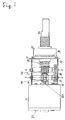
- Figure 1 shows the side view of the electromotive adjustable resistor of the present invention.
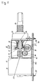
- Figure 2 shows the partial sectional view of the electromotive adjustable resistor of the present invention which is connected to the circuit board.
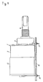
- Figure 3 shows the perspective view of the electromotive adjustable resistor of the present invention.
- Figure 4 shows the conventional electromotive adjustable resistor which is connected to the circuit board.
- Figure 5 shows the partial sectional view of the conventional electromotive adjustable resistor.
- Figure 6 shows the AA sectional view of the figure 5 showing the construction in the gear case of the conventional electromotive adjustable resistor.
- FIGS 1,2,3 show the electromotive adjustable resistor of the present invention.
- a gear case 22 is covered with a steel plate 21.
- an adjustable resistor 23 having a resistance adjusting shaft 24 extending to the both sides of it, is fixed on the steel plate 21.
- a driving component 26 is fixed on the resistance adjusting shaft 24 which is extending into the gear case 22.
- a second worm wheel 29 is assembled concentrically around the resistance adjusting shaft 24 and biased to the driving component 26 by a spring 28.
- a second worm wheel 29 and the driving component 26 are coupled frictionally so that the transmittion of the rotating torque between them is capable.
- a pad 31 is inserted to stabilize the frictional condition between them.
- a first worm gear 33 is fixed on the motor shaft 32A of the electric motor 32.
- a first gear shaft 41 is assembled in the gear case 22 rotatively arround the axis DD having a first worm wheel 34, which engages with the first worm gear 33, and a first sylindrical gear 35 fixed on it.
- a second gear shaft 42 is assembled in the gear case 22 rotatively arround the axis EE having a second sylindrical gear 36, which engages with the first sylindrical gear 35, and a second worm gear 37, which engages with the second worm wheel 29, fixed on it.
- the gear train of the electromotive adjustable resistor of the present invention comprises two worm gear engagements and a sylindrical gear engagement.
- a sylindrical gear engagement makes a space between the two worm gear engagements. That is, a sylindrical gear engagement makes the space between the resistance adjusting shaft and the motor shaft along the axis of the both shafts.
- the rotation of the motor shaft 32A trasmits to the second worm wheel 29 via first worm gear 33, first worm wheel 34, first sylindrical gear 35, second sylindrical gear 36, and second worm gear 37.
- the rotating torque of the second worm wheel 29 transmits to the driving component 26 through the friction coupling between them and rotates the resistance adjusting shaft 24, so that the resistance of the adjustable resistor is changed.
- the resistance of the adjustable resistor 23 is also changed by rotating the resistance adjusting shaft 24, which is extending to the direction counter side for the gear case 22, manually.
- the driving component 26 slips against the second worm wheel 29 through the inserted pad 31 between them since the the second worm wheel 29 is stoped rotation by the second worm gear 37.
- the electric connecting terminal 38 is extending to the direction at right angle to the axis of the resistance adjusting shaft 24 of the adjustable resistor 23
- the electric connecting terminal 39 is extending to the direction at right angle to the axis of the motor shaft 32A
- both electric connecting terminals 38 and 39 are extending to the same direction for the convenience of connecting them to the circuit board.
- the first gear shaft 41 and the electric connecting terminal 39 both exist in the same direction from the axis of the motor shaft 32A and the second gear shaft 42 and the electric connecting terminal 38 both exist in the same direction from the axis of the resistance adjusting shaft 24 of the adjustable resistor 23.
Landscapes
- Engineering & Computer Science (AREA)
- Microelectronics & Electronic Packaging (AREA)
- Adjustable Resistors (AREA)
Applications Claiming Priority (2)
| Application Number | Priority Date | Filing Date | Title |
|---|---|---|---|
| JP252474/92 | 1992-09-22 | ||
| JP4252474A JP2959295B2 (ja) | 1992-09-22 | 1992-09-22 | モータ駆動式可変抵抗器 |
Publications (3)
| Publication Number | Publication Date |
|---|---|
| EP0589259A2 true EP0589259A2 (de) | 1994-03-30 |
| EP0589259A3 EP0589259A3 (de) | 1994-08-03 |
| EP0589259B1 EP0589259B1 (de) | 1997-04-16 |
Family
ID=17237888
Family Applications (1)
| Application Number | Title | Priority Date | Filing Date |
|---|---|---|---|
| EP93114092A Expired - Lifetime EP0589259B1 (de) | 1992-09-22 | 1993-09-02 | Elektromotorisch einstellbarer Widerstand |
Country Status (5)
| Country | Link |
|---|---|
| US (1) | US5376914A (de) |
| EP (1) | EP0589259B1 (de) |
| JP (1) | JP2959295B2 (de) |
| KR (1) | KR970004563B1 (de) |
| DE (1) | DE69309826T2 (de) |
Cited By (2)
| Publication number | Priority date | Publication date | Assignee | Title |
|---|---|---|---|---|
| GB2292014A (en) * | 1994-07-28 | 1996-02-07 | Heidelberger Druckmasch Ag | Motor driven potentiometer for analog signal controller |
| NL1005070C2 (nl) * | 1997-01-23 | 1998-07-27 | Dsm Nv | Coatingsamenstelling, werkwijze voor het bereiden en het gebruik in anticorrosieverf. |
Families Citing this family (7)
| Publication number | Priority date | Publication date | Assignee | Title |
|---|---|---|---|---|
| US6270239B1 (en) * | 1998-04-27 | 2001-08-07 | Electronic Theatre Controls, Inc. | Fader wheel for lighting control console |
| EP1114765B1 (de) * | 1999-12-08 | 2006-09-06 | Alps Electric Co., Ltd. | Winkelsensor, wodurch Klappern durch Spiel zwischen Zahnrädern innerhalb des Winkelsensor verhindert wird |
| DE10032187A1 (de) * | 2000-07-01 | 2002-01-17 | Bosch Gmbh Robert | Verstellantrieb mit einstellbarem Potentiometer |
| US7116210B2 (en) * | 2004-05-05 | 2006-10-03 | Cts Corporation | Actuator with integral position sensor |
| US20070008063A1 (en) * | 2004-08-13 | 2007-01-11 | Cts Corporation | Rotary actuator with non-contacting position sensor |
| CN102326053B (zh) | 2009-02-17 | 2015-02-18 | Cts公司 | 旋转位置传感器 |
| JP7360932B2 (ja) * | 2019-12-25 | 2023-10-13 | 東京コスモス電機株式会社 | 可変抵抗装置 |
Family Cites Families (14)
| Publication number | Priority date | Publication date | Assignee | Title |
|---|---|---|---|---|
| US1124280A (en) * | 1911-03-15 | 1915-01-12 | John C Brackett | Electric-motor-controlling means. |
| US2248711A (en) * | 1936-10-02 | 1941-07-08 | Stewart Warner Corp | Sending unit for electric speedometers |
| US2575151A (en) * | 1947-10-17 | 1951-11-13 | Koehler Mfg Co | Battery-charging apparatus |
| US2863281A (en) * | 1956-01-31 | 1958-12-09 | Cons Electronics Ind | Resettable drive mechanism for potentiometer or the like |
| US3100883A (en) * | 1960-11-21 | 1963-08-13 | Daystrom Inc | Phasable ganged potentiometer |
| US3547240A (en) * | 1968-09-19 | 1970-12-15 | Frank Holper | Clutch means for selectively coupling a single input to one or more plural outputs |
| JPS5245904B2 (de) * | 1973-10-30 | 1977-11-19 | ||
| US3982220A (en) * | 1974-03-04 | 1976-09-21 | Cts Corporation | Variable resistance control |
| US4646055A (en) * | 1984-09-01 | 1987-02-24 | Murata Manufacturing Co., Ltd. | Rotary trimmer potentiometer |
| US4931710A (en) * | 1988-04-05 | 1990-06-05 | Eaton Corporation | Servoactuator with feedback and method of calibrating |
| JPH0293813U (de) * | 1989-01-13 | 1990-07-25 | ||
| JPH03201505A (ja) * | 1989-12-28 | 1991-09-03 | Matsushita Electric Ind Co Ltd | 回転形モータ駆動可変抵抗器 |
| JP2926926B2 (ja) * | 1990-07-25 | 1999-07-28 | 松下電器産業株式会社 | モーター駆動可変抵抗器 |
| JPH04112501A (ja) * | 1990-08-31 | 1992-04-14 | Matsushita Electric Ind Co Ltd | モーター駆動可変抵抗器 |
-
1992
- 1992-09-22 JP JP4252474A patent/JP2959295B2/ja not_active Expired - Fee Related
-
1993
- 1993-09-02 EP EP93114092A patent/EP0589259B1/de not_active Expired - Lifetime
- 1993-09-02 DE DE69309826T patent/DE69309826T2/de not_active Expired - Fee Related
- 1993-09-16 US US08/121,417 patent/US5376914A/en not_active Expired - Lifetime
- 1993-09-21 KR KR1019930019090A patent/KR970004563B1/ko not_active Expired - Fee Related
Cited By (3)
| Publication number | Priority date | Publication date | Assignee | Title |
|---|---|---|---|---|
| GB2292014A (en) * | 1994-07-28 | 1996-02-07 | Heidelberger Druckmasch Ag | Motor driven potentiometer for analog signal controller |
| NL1005070C2 (nl) * | 1997-01-23 | 1998-07-27 | Dsm Nv | Coatingsamenstelling, werkwijze voor het bereiden en het gebruik in anticorrosieverf. |
| WO1998032805A1 (en) * | 1997-01-23 | 1998-07-30 | Dsm N.V. | Coating composition, method for the preparation thereof and use thereof in anticorrosive paint |
Also Published As
| Publication number | Publication date |
|---|---|
| KR940007906A (ko) | 1994-04-28 |
| KR970004563B1 (ko) | 1997-03-29 |
| EP0589259A3 (de) | 1994-08-03 |
| JPH06104103A (ja) | 1994-04-15 |
| DE69309826D1 (de) | 1997-05-22 |
| JP2959295B2 (ja) | 1999-10-06 |
| EP0589259B1 (de) | 1997-04-16 |
| US5376914A (en) | 1994-12-27 |
| DE69309826T2 (de) | 1997-07-31 |
Similar Documents
| Publication | Publication Date | Title |
|---|---|---|
| EP0589259A2 (de) | Elektromotorisch einstellbarer Widerstand | |
| JPH11194007A (ja) | 回転角度センサ、この回転角度センサを用いたトルクセンサ、このトルクセンサを用いた電動パワーステアリング装置 | |
| JP2004503196A (ja) | 調整可能なポテンショメータを備えた調整駆動装置 | |
| US5024307A (en) | Free wheel hub system | |
| JP2970293B2 (ja) | 切断装置 | |
| CN213354600U (zh) | 一种方向盘及移动式载体 | |
| JPS5915176U (ja) | 複合表示機能をもつアワメ−タの輪列構造 | |
| JPH10297372A (ja) | 車両用アウタミラー装置 | |
| JP3111872B2 (ja) | 駆動装置 | |
| JPH0525351Y2 (de) | ||
| JPS5979468U (ja) | 電動式動力舵取装置 | |
| JPS5979467U (ja) | 電動式動力舵取装置 | |
| JPS58180074U (ja) | シ−ト巻取式筆記板装置 | |
| JPS59121526U (ja) | 回転力伝達装置 | |
| JPH05187452A (ja) | 軸継手 | |
| JPS58659U (ja) | ギヤ−ドモ−タのクラツチ機構 | |
| JPS58165360U (ja) | 差動装置 | |
| JPS5826204U (ja) | 電動伸縮形アンテナ装置用クラツチ機構 | |
| JPS6411003U (de) | ||
| JPS613752U (ja) | 電動可倒式ドアミラ− | |
| JPS59183765U (ja) | トルク調整装置 | |
| JPS59108858U (ja) | 歯車式動力伝達装置 | |
| JPH04109227U (ja) | 等速自在継手 | |
| JPS5970872U (ja) | 電動式動力舵取装置 | |
| JPS6126654U (ja) | ドアミラ−構造 |
Legal Events
| Date | Code | Title | Description |
|---|---|---|---|
| PUAI | Public reference made under article 153(3) epc to a published international application that has entered the european phase |
Free format text: ORIGINAL CODE: 0009012 |
|
| AK | Designated contracting states |
Kind code of ref document: A2 Designated state(s): DE FR GB |
|
| PUAL | Search report despatched |
Free format text: ORIGINAL CODE: 0009013 |
|
| AK | Designated contracting states |
Kind code of ref document: A3 Designated state(s): DE FR GB |
|
| 17P | Request for examination filed |
Effective date: 19941013 |
|
| 17Q | First examination report despatched |
Effective date: 19951113 |
|
| GRAG | Despatch of communication of intention to grant |
Free format text: ORIGINAL CODE: EPIDOS AGRA |
|
| GRAH | Despatch of communication of intention to grant a patent |
Free format text: ORIGINAL CODE: EPIDOS IGRA |
|
| GRAH | Despatch of communication of intention to grant a patent |
Free format text: ORIGINAL CODE: EPIDOS IGRA |
|
| GRAA | (expected) grant |
Free format text: ORIGINAL CODE: 0009210 |
|
| AK | Designated contracting states |
Kind code of ref document: B1 Designated state(s): DE FR GB |
|
| REF | Corresponds to: |
Ref document number: 69309826 Country of ref document: DE Date of ref document: 19970522 |
|
| ET | Fr: translation filed | ||
| PLBE | No opposition filed within time limit |
Free format text: ORIGINAL CODE: 0009261 |
|
| 26N | No opposition filed | ||
| REG | Reference to a national code |
Ref country code: GB Ref legal event code: IF02 |
|
| PGFP | Annual fee paid to national office [announced via postgrant information from national office to epo] |
Ref country code: GB Payment date: 20060830 Year of fee payment: 14 |
|
| PGFP | Annual fee paid to national office [announced via postgrant information from national office to epo] |
Ref country code: FR Payment date: 20060908 Year of fee payment: 14 |
|
| GBPC | Gb: european patent ceased through non-payment of renewal fee |
Effective date: 20070902 |
|
| REG | Reference to a national code |
Ref country code: FR Ref legal event code: ST Effective date: 20080531 |
|
| PG25 | Lapsed in a contracting state [announced via postgrant information from national office to epo] |
Ref country code: FR Free format text: LAPSE BECAUSE OF NON-PAYMENT OF DUE FEES Effective date: 20071001 |
|
| PG25 | Lapsed in a contracting state [announced via postgrant information from national office to epo] |
Ref country code: GB Free format text: LAPSE BECAUSE OF NON-PAYMENT OF DUE FEES Effective date: 20070902 |
|
| PGFP | Annual fee paid to national office [announced via postgrant information from national office to epo] |
Ref country code: DE Payment date: 20080919 Year of fee payment: 16 |
|
| PG25 | Lapsed in a contracting state [announced via postgrant information from national office to epo] |
Ref country code: DE Free format text: LAPSE BECAUSE OF NON-PAYMENT OF DUE FEES Effective date: 20100401 |