EP0589377B1 - Filtre à carburant - Google Patents
Filtre à carburant Download PDFInfo
- Publication number
- EP0589377B1 EP0589377B1 EP93115058A EP93115058A EP0589377B1 EP 0589377 B1 EP0589377 B1 EP 0589377B1 EP 93115058 A EP93115058 A EP 93115058A EP 93115058 A EP93115058 A EP 93115058A EP 0589377 B1 EP0589377 B1 EP 0589377B1
- Authority
- EP
- European Patent Office
- Prior art keywords
- filter
- sealing
- cover
- housing
- location
- Prior art date
- Legal status (The legal status is an assumption and is not a legal conclusion. Google has not performed a legal analysis and makes no representation as to the accuracy of the status listed.)
- Expired - Lifetime
Links
Images

Classifications
-
- B—PERFORMING OPERATIONS; TRANSPORTING
- B01—PHYSICAL OR CHEMICAL PROCESSES OR APPARATUS IN GENERAL
- B01D—SEPARATION
- B01D35/00—Filtering devices having features not specifically covered by groups B01D24/00 - B01D33/00, or for applications not specifically covered by groups B01D24/00 - B01D33/00; Auxiliary devices for filtration; Filter housing constructions
- B01D35/30—Filter housing constructions
-
- F—MECHANICAL ENGINEERING; LIGHTING; HEATING; WEAPONS; BLASTING
- F02—COMBUSTION ENGINES; HOT-GAS OR COMBUSTION-PRODUCT ENGINE PLANTS
- F02M—SUPPLYING COMBUSTION ENGINES IN GENERAL WITH COMBUSTIBLE MIXTURES OR CONSTITUENTS THEREOF
- F02M37/00—Apparatus or systems for feeding liquid fuel from storage containers to carburettors or fuel-injection apparatus; Arrangements for purifying liquid fuel specially adapted for, or arranged on, internal-combustion engines
- F02M37/22—Arrangements for purifying liquid fuel specially adapted for, or arranged on, internal-combustion engines, e.g. arrangements in the feeding system
- F02M37/32—Arrangements for purifying liquid fuel specially adapted for, or arranged on, internal-combustion engines, e.g. arrangements in the feeding system characterised by filters or filter arrangements
- F02M37/42—Installation or removal of filters
Definitions
- the invention relates to a filter for cleaning fuel according to the type specified in the preamble of the main claim.
- Such a filter for cleaning fuel is already known from US Pat. No. 4,502,956, on the filter cover of which a filter housing is screwed on in an easily detachable manner by means of a union nut.
- the filter is designed here as a so-called housing filter with exchangeable filter inserts, with three sealing points always lying on the filter cover, two of which are axially displaceable with regard to the plug-in solution, while the third seal is axially fixed.
- the disadvantage of this filter is the high outlay for this type of housing filter, which is designed as a multi-stage filter, in which several filter inserts are connected in series.
- the filter cover is specially designed for this type of construction and is not suitable for attaching another filter housing.
- the filter cover itself cannot therefore be used universally.
- the sealing at the middle and outer sealing point takes place unfavorably on relatively large outside diameters.
- the hand pump on the filter cover is also permanently installed, so that the filter cover is not suitable for a modular design.
- the filter according to the invention for fuel with the characterizing features of the main claim has the advantage that it allows an easy-to-use plug-in solution with a favorable seal between the dirty side and clean side and easy attachment by a union nut, different filter housings being attachable to the filter cover.
- the filter cover can be used for different filter variants without changes, whereby it is primarily suitable for a housing filter with an exchangeable filter insert and for a disposable change box.
- the filter cover is relatively simple and compact and is suitable for integrating additional functions.
- connection bores are designed in such a way that they are suitable for commercially available quick connection plug connections, so that complex threaded bores can be dispensed with.
- the filter cover of the filter according to claim 7 is designed in a modular design, so that other module components, such as a heating module, a fuel return module or a hand pump module, can also be attached.
- module components such as a heating module, a fuel return module or a hand pump module.
- the filter insert is arranged interchangeably in the filter housing, so that the filter housing itself can be reused.
- the filter housing is designed as part of a disposable change box, so that different customer requirements can be met in a cost-effective manner with only one filter cover. Further advantageous embodiments result from the remaining claims, the description and the drawing.
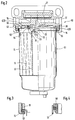
- FIG. 1 shows a longitudinal section through a first filter for cleaning fuel with an attached housing filter, partly in section
- FIG. 2 shows a longitudinal section through a second filter, in which a disposable interchangeable box is attached to the same filter cover
- FIG. 3 shows a modified clamping the flanging of the interchangeable box through the union nut
- FIG. 4 shows a modified design of a sleeve seal.
- FIG. 1 shows a longitudinal section through a filter 10 as it is used for cleaning fuel.
- the filter 10 consists essentially of a filter cover 11 and a so-called housing filter 12 with an exchangeable filter insert 13, the actual filter housing 14 being releasably attached to the filter cover 11 by means of a union nut 15.
- the filter cover 11 essentially has the basic shape of a flat, circular disk, in which the connections for the inlet 16 and outlet 17 are arranged in the same radial plane and diametrically offset from one another.
- the filter cover 11 can be made of glass-fiber reinforced plastic or as an aluminum die-cast part and has a collar 18 with an external thread 19 which projects downward from the connections 16, 17 and onto which the union nut 15 with an L-shaped cross section is screwed.
- a centrally arranged, axially extending first pipe socket 22 is arranged, which is in pressure medium connection with the drain connection 17.
- a second pipe socket 23 is formed on the end face 21, the axial length of which is approximately half that of the first pipe socket 22.
- An annular space 24 formed between the two pipe sockets 22, 23 is in the filter cover 11 via a cross connection 25 with a transverse channel 26 in an end cap 27 and with the inlet connection 16 in connection.
- an annular groove 28 is formed on the end face 21 of the filter cover 11 next to the collar 18, in which a flat sealing ring 29 is inserted.
- the filter cover 11 is formed on its end face 21 such that three sealing points 122, 123, 128 are possible on it.
- first pipe socket 22 is a so-called inner sealing point 122
- second pipe socket 23 is assigned to a central sealing point 123
- annular groove 28 forms an outer sealing point 128.
- At the first pipe socket 22 there is an axially displaceable sealing sleeve 31 which is fastened on a support pipe 32 of the filter insert 13. In this way, sealing collar 31 and pipe socket 22 form a first, inner seal 33 which separates the dirty and clean side from one another in the filter.
- a bent edge 34 of the filter housing 14 presses against the flat sealing ring 29 and thereby forms a second, outer seal 35 which seals the inside of the filter housing 14 from the outside.
- the edge 34 of the filter housing 14 has a radially outwardly projecting collar 36 with which it is supported on the union nut 15. All three sealing points 122, 123, 128 are thus arranged on the filter cover 11 in a space-saving manner in the same radial plane as the union nut 15.
- the filter insert 13 is designed here as an axially flow-through winding, which is arranged in a manner known per se between the support tube 32 and an outside cardboard tube 37.
- the cardboard tube 37 is supported on the one hand on a perforated plate 38 and on the other hand on the flat sealing ring 29, so that the filter insert 13 is fixed axially in the filter housing 14.
- the filter cover 11 has on its end face 39 opposite the end face 21 a socket connection 41 into which the end cap 27 with its plug connection 42 is inserted.
- the end cap 27 which is designed in a modular design, other module components can also be used in the filter cover 11, which, for example, function as a hand pump, a electrical heating or a fuel return can take over.
- the seal between the filter cover 11 and the end cap 27 is carried out by a flat sealing element 43.
- a fastening flange 44 is arranged on the filter cover 11.
- connections for inlet 16 and outlet 17 are designed with such graduated connection bores that commercially available quick-connect plug connections can be used in order to enable an inexpensive and quick connection of the fuel pipelines.
- the mode of operation of the filter 10 is essentially known and is therefore only briefly explained.
- the fuel to be cleaned flows from the inlet connection 16 into the end cap 27 and passes via its transverse channel 26 and the transverse connection 25 in the filter cover 11 into the annular space 24 between the two pipe sockets 22, 23 and thus onto the dirty side of the housing filter 12.
- the fuel flows through axially downward the winding element 13 in order to then subsequently reach the drain connection 17 in a central cleaned manner via the support tube 32 and the first pipe socket 22.
- the first seal 33 ensures a separation of the dirt side and the clean side, while the second seal 35 seals against the outside.
- the filter 10 is designed as an easy-to-use plug-in solution, the housing filter 12 being easily detachably fastened to the filter cover 11 with the aid of the union nut 15.
- the union nut 15 presses the rim 34 of the filter housing 14 firmly against the flat sealing ring 29 via the radially bent collar 36; the first seal 33 remains axially displaceable.
- the sealing collar 31 is expediently designed as a rubber seal. If the filter insert 13 is clogged, the housing filter 12 can be removed from the filter cover 11 by loosening the union nut 15 and then the filter insert 13 are disposed of.
- the filter housing 14 therefore remains usable in a cost-effective manner.
- FIG. 2 shows a longitudinal section through a second filter 50, which differs from the filter 10 according to FIG. 1 as follows, the same reference numerals being used for the same components.
- the same filter cover 11 is used for the filter 50 as for the filter 10, but a disposable change box 51 is attached to its end face 21.
- the change box 51 has in its filter housing 14 the same filter insert 13 with support tube 32, but in which the outer cardboard tube 37 is omitted.
- the housing 14 is blocked off at its upper edge by a metallic closure cover 52, which on the one hand is tightly and firmly connected to the housing 14 in a flanged edge 53, while it has a sealing collar 54 on its inner edge.
- the sealing collar 54 which is expediently designed as a rubber seal, forms, together with the central sealing point 123 on the second pipe socket 23, the so-called outer seal 35, which seals the interior of the interchangeable box 51 from the outside.
- the outer seal 35 is on a much smaller diameter than the outer sealing point 128; this not only reduces the forces to be transmitted by the union nut 15, but also the construction effort is reduced and the safety is increased by the shorter sealing length.
- the reinforced flange 53 is used as a clamping point at which the filter housing 14 is pressed against the filter cover 11 by means of the union nut 15.
- the closure cover 52 is supported in the axial direction on an annular web 55 which delimits the annular groove 28.
- the change box 51 is axially fixed in this way, while the two sealing points 33 and 35 on the pipe socket 22 and 23 axially are slidably arranged.
- the interchangeable box 51 can be plugged in axially and quickly on the filter cover 11 and fastened with the union nut 15, no significant changes having to be made on the filter cover 11 itself.
- the flat sealing ring 29 in the annular groove 28 can be saved.
- one and the same filter cover 11 can thus be used for different filter variants, an easy-to-use plug-in solution with attachment by means of a union nut being retained.
- fuel lines can be installed easily and quickly in the filter cover 11 and additional functions can be integrated on the filter cover 11 with the aid of the modular design.
- FIG. 3 shows as a detail a variant of an interchangeable box in which the flanged edge 57 is formed in a radial direction, so that it can be clamped between the union nut 15 and the collar 18.
- FIG. 4 shows as a detail a variant in which another rubber sealing sleeve 58 is used on the support tube 32.
Landscapes
- Engineering & Computer Science (AREA)
- Chemical & Material Sciences (AREA)
- Combustion & Propulsion (AREA)
- Mechanical Engineering (AREA)
- General Engineering & Computer Science (AREA)
- Chemical Kinetics & Catalysis (AREA)
- Filtration Of Liquid (AREA)
Claims (11)
- Filtre (10, 50) servant à nettoyer du carburant, avec un couvercle de filtre (11) présentant les raccordements pour l'arrivée (16) et le départ (17), couvercle sur lequel un boîtier de filtre (14) est fixé de façon amovible à l'aide d'un écrou d'accouplement (15), l'écrou d'accouplement (15) entourant, en le serrant sur son pourtour, le boîtier de filtre (14) qui reçoit une cartouche filtrante (13), et dans le cas duquel sont prévues sur le couvercle de filtre (11) des zones d'étanchéité (122, 123, 128) pour les joints d'étanchéité, zones d'étanchéité parmi lesquelles une zone d'étanchéité intérieure (122) se trouve entre le côté sale et le côté propre et présente, sur le couvercle de filtre (11) un ajutage tubulaire central qui convient pour un enfoncement axial du boîtier de filtre (14) sur le couvercle de filtre (11), une zone d'étanchéité médiane (123) sur le couvercle de filtre (11), entre les zones d'étanchéité intérieure et extérieure (122, 128) et la zone d'étanchéité extérieure (128), assure l'étanchéité de la chambre interne du boîtier de filtre (14) vers l'extérieur, les trois zones d'étanchéité (122, 123, 128) se trouvant dans le même plan radial que l'écrou d'accouplement (15) sur le couvercle de filtre (11), filtre caractérisé en ce que la zone d'étanchéité médiane (123) est constitué sur le couvercle de filtre (11) sous la forme d'un ajutage de forme tubulaire (23), en ce que la chambre annulaire (24) comprise entre les deux ajutages tubulaires (22, 23) est reliée au raccord d'arrivée (16) et l'ajutage central tubulaire (22) est relié de façon fluide au raccord de sortie (17), en ce que, parmi les trois zones d'étanchéité (122, 123, 128), deux seulement sont constituées comme des joints d'étanchéité (33, 35), le joint d'étanchéité (35) qui obture la chambre interne du boîtier de filtre (14) vers l'extérieur, étant constitué de façon déplaçable au choix sur la zone extérieure d'étanchéité (128) ou sur la zone médiane d'étanchéité (123), par le boîtier de filtre interchangeable (14, 51).
- Filtre selon la revendication 1, caractérisé en ce que les joints d'étanchéité (33, 35) sont constitués sur la zone d'étanchéité intérieure et la zone d'étanchéité moyenne (122, 123) avec des manchettes d'étanchéité (31, 54) pouvant coulisser axialement sur l'ajutage tubulaire (22, 23), manchettes qui sont en particulier en caoutchouc.
- Filtre selon la revendication 1 ou 2, caractérisé en ce que la zone d'étanchéité extérieure (128) du couvercle de filtre (11) présente une rainure annulaire (28) ouverte en direction du boîtier de filtre (14), rainure dans laquelle peut être insérée une bague d'étanchéité plate (29).
- Filtre selon l'une des revendications 1 à 3, caractérisé en ce que la distance de la zone d'étanchéité médiane (123) par rapport à la zone d'étanchéité intérieure (122) est plus petite que sa distance par rapport à la zone d'étanchéité extérieure (128).
- Filtre selon l'une des revendications 1 à 4, caractérisé en ce que les raccords pour l'arrivée (16) et le départ (17) sont disposés dans le même plan radial et sont en particulier coaxiaux l'un par rapport à l'autre.
- Filtre selon la revendication 5, caractérisé en ce que les alésages de raccordement pour l'arrivée (16) et le départ (17) sont constitués pour des liaisons à enfichage à raccordement rapide.
- Filtre selon l'une ou plusieurs des revendications 1 à 6, caractérisé en ce que, sur le couvercle de filtre (11), on dispose sur la face frontale (39) qui se trouve à l'opposé du boîtier de filtre (14), un chapeau de fermeture (27) constitué selon un mode de construction modulaire, chapeau de fermeture qui présente un canal (26) par lequel on fait passer le carburant du raccord d'arrivée (16) à la chambre annulaire (24) entre les deux ajutages tubulaires (22, 23).
- Filtre selon l'une ou plusieurs des revendications 1 à 7, caractérisé en ce que le boîtier de filtre (14) est constitué sous la forme d'un filtre à boîtier (12) qui présente une cartouche filtrante interchangeable (13) et dont les joints d'étanchéité (33, 35) reposent sur la zone d'étanchéité intérieure (122) et la zone d'étanchéité extérieure (128).
- Filtre selon la revendication 8, caractérisé en ce que le boîtier de filtre (14) présente une manchette d'étanchéité (31), associée au joint d'étanchéité intérieur (33) en particulier un joint d'étanchéité en caoutchouc qui peut coulisser axialement tandis que son bord, se trouvant sur le diamètre extérieur (34), est pressé axialement sur la bague d'étanchéité plate (29), un col (36) faisant saillie radialement vers l'extérieur, étant constitué pour cela, col qui repose sur l'écrou d'accouplement (15).
- Filtre selon l'une ou plusieurs des revendications 1 à 7, caractérisé en ce que le boîtier de filtre (14) est constitué comme une partie d'une boîte interchangeable jetable (51) dont le bord de repliement (53) sert, sur le diamètre extérieur d'un couvercle de fermeture (52), de zone de serrage pour l'écrou d'accouplement (15), tandis que la paroi intérieure du couvercle de fermeture (52) porte une manchette d'étanchéité (54) qui peut coulisser axialement sur le second ajutage tubulaire (23) et forme de cette façon le joint d'étanchéité extérieur (35) sur la zone d'étanchéité médiane (123), en ce que le couvercle de fermeture (52) prend appui axialement sur une entretoise (55) du couvercle de filtre (11), et en ce que le joint d'étanchéité intérieur (33) est formé par une manchette d'étanchéité (31) sur un tuyau d'appui (32) de la cartouche de filtre (13), qui repose sur l'ajutage tubulaire central (22).
- Filtre selon la revendication 10, caractérisé en ce que le bord replié (57) du boîtier de filtre (14) est constitué dans le sens radial et est inséré axialement entre l'écrou d'accouplement (15) et le couvercle de filtre (11).
Applications Claiming Priority (2)
| Application Number | Priority Date | Filing Date | Title |
|---|---|---|---|
| DE4231999 | 1992-09-24 | ||
| DE4231999A DE4231999A1 (de) | 1992-09-24 | 1992-09-24 | Filter zum Reinigen von Kraftstoff |
Publications (2)
| Publication Number | Publication Date |
|---|---|
| EP0589377A1 EP0589377A1 (fr) | 1994-03-30 |
| EP0589377B1 true EP0589377B1 (fr) | 1996-07-24 |
Family
ID=6468729
Family Applications (1)
| Application Number | Title | Priority Date | Filing Date |
|---|---|---|---|
| EP93115058A Expired - Lifetime EP0589377B1 (fr) | 1992-09-24 | 1993-09-18 | Filtre à carburant |
Country Status (3)
| Country | Link |
|---|---|
| EP (1) | EP0589377B1 (fr) |
| DE (2) | DE4231999A1 (fr) |
| ES (1) | ES2090804T3 (fr) |
Families Citing this family (11)
| Publication number | Priority date | Publication date | Assignee | Title |
|---|---|---|---|---|
| DE4321171A1 (de) * | 1993-06-25 | 1995-01-05 | Bosch Gmbh Robert | Flüssigkeitsfilter für Dieselkraftstoff |
| DE4432529A1 (de) | 1994-09-13 | 1996-03-14 | Bosch Gmbh Robert | Wechselfilterelement zum Reinigen von Kraftstoff und Filtergehäuse zum Einbau des Wechselfilterelementes |
| DE19642641C2 (de) * | 1995-11-27 | 1998-03-19 | Knecht Filterwerke Gmbh | Kunststoff-Schraubdeckel in Glockenform für ein Filtergehäuse |
| US5985144A (en) * | 1997-07-03 | 1999-11-16 | Stanadyne Automotive Corp. | Reverse flow cartridge |
| RU2135815C1 (ru) * | 1997-12-30 | 1999-08-27 | Лоскутов Владимир Сергеевич | Фильтр-заборник топлива из бака |
| US20020125188A1 (en) * | 2001-03-06 | 2002-09-12 | Hacker John R. | Liquid filter having interchangeable spin-on canister filter and cartridge filter, and methods |
| JP4376716B2 (ja) * | 2004-07-20 | 2009-12-02 | トヨタ自動車株式会社 | フューエルフィルタ |
| IT1401932B1 (it) * | 2010-09-15 | 2013-08-28 | Bosch Gmbh Robert | Gruppo di pompaggio per alimentare combustibile, preferibilmente gasolio, ad un motore a combustione interna |
| ITFO20110012A1 (it) * | 2011-09-27 | 2013-03-28 | Valerio Vernocchi | Unita di filtrazione e kit comprendente tale unita |
| DE102017011693A1 (de) * | 2017-12-18 | 2019-06-19 | Mann+Hummel Gmbh | Kraftstofffilter zur Erwärmung und Reinigung von Kraftstoff und Filtergehäuse |
| CN113304517A (zh) * | 2021-05-25 | 2021-08-27 | 刘万斌 | 便拆式油过滤器 |
Family Cites Families (6)
| Publication number | Priority date | Publication date | Assignee | Title |
|---|---|---|---|---|
| US2287344A (en) * | 1939-02-07 | 1942-06-23 | Easton Harold Sidney | Filter |
| AT226483B (de) * | 1961-06-14 | 1963-03-25 | Alfred Knecht | Schmierölfilter, insbesondere für Brennkraftmaschinen |
| US3608726A (en) * | 1969-03-17 | 1971-09-28 | Lucas Industries Ltd | Liquid-filtering equipment |
| US4502956A (en) * | 1982-02-24 | 1985-03-05 | Racor Industries, Inc. | Filter assembly |
| JPH01100360A (ja) * | 1987-10-13 | 1989-04-18 | Sanshin Ind Co Ltd | 船舶推進機の燃料供給装置 |
| US5171430A (en) * | 1991-05-17 | 1992-12-15 | Fleetguard, Inc. | Plastic filter |
-
1992
- 1992-09-24 DE DE4231999A patent/DE4231999A1/de not_active Withdrawn
-
1993
- 1993-09-18 DE DE59303307T patent/DE59303307D1/de not_active Expired - Fee Related
- 1993-09-18 EP EP93115058A patent/EP0589377B1/fr not_active Expired - Lifetime
- 1993-09-18 ES ES93115058T patent/ES2090804T3/es not_active Expired - Lifetime
Also Published As
| Publication number | Publication date |
|---|---|
| ES2090804T3 (es) | 1996-10-16 |
| DE59303307D1 (de) | 1996-08-29 |
| DE4231999A1 (de) | 1994-03-31 |
| EP0589377A1 (fr) | 1994-03-30 |
Similar Documents
| Publication | Publication Date | Title |
|---|---|---|
| DE2642083C2 (de) | Filtereinrichtung für das Ansaugsystem bei Brennkraftmaschinen in Kraftfahrzeugen | |
| DE60204885T2 (de) | Anschraubbarer filter und entsprechender filterkopf | |
| DE69215795T2 (de) | Tropfwassergeschütztes Austauschsystem für Kraftstoffilter | |
| DE19752376A1 (de) | Filter | |
| EP0589377B1 (fr) | Filtre à carburant | |
| DE19538883A1 (de) | Filter für Flüssigkeiten, insbesondere Dieselkraftstoff | |
| WO2008014846A1 (fr) | Dispositif de filtration | |
| EP0943796B1 (fr) | Filtre à liquide pour purifier du carburant | |
| EP0385113A2 (fr) | Filtre de liquide | |
| DE2621888B2 (de) | Stroemungsfilter | |
| EP1255604B1 (fr) | Element filtrant pour filtre a liquides | |
| EP0537521A1 (fr) | Filtre pour un liquide | |
| EP0537520B1 (fr) | Filtre pour un liquide | |
| DE7917272U1 (de) | Mehrteiliges filtergehaeuse | |
| DE19605952A1 (de) | Vorrichtung zum Versorgen einer Brennkraftmaschine eines Kraftfahrzeugs mit in einem Vorratstank vorhandenem Kraftstoff | |
| EP1090666B1 (fr) | Plaque adaptatrice pour un filtre à liquide et filtre à liquide connecté à des tuyaux souples | |
| DE9113019U1 (de) | Flüssigkeitsfilter | |
| DE1461431A1 (de) | Filter | |
| DE102022116617A1 (de) | Wechselfilter für eine Ölfiltervorrichtung einer Maschine und Ölfiltervorrichtung | |
| EP0581178B1 (fr) | Installation de couvercles de filtres à construction modulaire | |
| DE3527802C2 (de) | Filteranordnung zum Einbau in den Strömungsweg einer Brennstoff-Förderpumpe | |
| DE2632441C3 (de) | Vorrichtung zum Filtern von Fluiden, insbesondere Flüssigkeiten | |
| EP0253388B1 (fr) | Dispositif de réglage de conduites d'arrosage de champs | |
| DE10240666A1 (de) | Flüssigkeitsfilter, insbesondere für Getriebeöl in Kraftfahrzeugen | |
| DE19856723A1 (de) | Filtereinsatz für ein einen Einlaß und einen Auslaß aufweisendes Kraftstoffilter |
Legal Events
| Date | Code | Title | Description |
|---|---|---|---|
| PUAI | Public reference made under article 153(3) epc to a published international application that has entered the european phase |
Free format text: ORIGINAL CODE: 0009012 |
|
| AK | Designated contracting states |
Kind code of ref document: A1 Designated state(s): DE ES FR GB IT |
|
| 17P | Request for examination filed |
Effective date: 19940930 |
|
| 17Q | First examination report despatched |
Effective date: 19941207 |
|
| GRAH | Despatch of communication of intention to grant a patent |
Free format text: ORIGINAL CODE: EPIDOS IGRA |
|
| GRAH | Despatch of communication of intention to grant a patent |
Free format text: ORIGINAL CODE: EPIDOS IGRA |
|
| GRAA | (expected) grant |
Free format text: ORIGINAL CODE: 0009210 |
|
| AK | Designated contracting states |
Kind code of ref document: B1 Designated state(s): DE ES FR GB IT |
|
| ET | Fr: translation filed | ||
| REF | Corresponds to: |
Ref document number: 59303307 Country of ref document: DE Date of ref document: 19960829 |
|
| ITF | It: translation for a ep patent filed | ||
| REG | Reference to a national code |
Ref country code: ES Ref legal event code: FG2A Ref document number: 2090804 Country of ref document: ES Kind code of ref document: T3 |
|
| GBT | Gb: translation of ep patent filed (gb section 77(6)(a)/1977) |
Effective date: 19960926 |
|
| REG | Reference to a national code |
Ref country code: ES Ref legal event code: FG2A Ref document number: 2090804 Country of ref document: ES Kind code of ref document: T3 |
|
| PLBE | No opposition filed within time limit |
Free format text: ORIGINAL CODE: 0009261 |
|
| 26N | No opposition filed | ||
| PGFP | Annual fee paid to national office [announced via postgrant information from national office to epo] |
Ref country code: FR Payment date: 19980925 Year of fee payment: 6 |
|
| PG25 | Lapsed in a contracting state [announced via postgrant information from national office to epo] |
Ref country code: FR Free format text: LAPSE BECAUSE OF NON-PAYMENT OF DUE FEES Effective date: 20000531 |
|
| REG | Reference to a national code |
Ref country code: FR Ref legal event code: ST |
|
| REG | Reference to a national code |
Ref country code: GB Ref legal event code: IF02 |
|
| PG25 | Lapsed in a contracting state [announced via postgrant information from national office to epo] |
Ref country code: IT Free format text: LAPSE BECAUSE OF NON-PAYMENT OF DUE FEES;WARNING: LAPSES OF ITALIAN PATENTS WITH EFFECTIVE DATE BEFORE 2007 MAY HAVE OCCURRED AT ANY TIME BEFORE 2007. THE CORRECT EFFECTIVE DATE MAY BE DIFFERENT FROM THE ONE RECORDED. Effective date: 20050918 |
|
| PGFP | Annual fee paid to national office [announced via postgrant information from national office to epo] |
Ref country code: DE Payment date: 20051118 Year of fee payment: 13 |
|
| PGFP | Annual fee paid to national office [announced via postgrant information from national office to epo] |
Ref country code: GB Payment date: 20060922 Year of fee payment: 14 |
|
| PGFP | Annual fee paid to national office [announced via postgrant information from national office to epo] |
Ref country code: ES Payment date: 20060926 Year of fee payment: 14 |
|
| PG25 | Lapsed in a contracting state [announced via postgrant information from national office to epo] |
Ref country code: DE Free format text: LAPSE BECAUSE OF NON-PAYMENT OF DUE FEES Effective date: 20070403 |
|
| GBPC | Gb: european patent ceased through non-payment of renewal fee |
Effective date: 20070918 |
|
| PG25 | Lapsed in a contracting state [announced via postgrant information from national office to epo] |
Ref country code: GB Free format text: LAPSE BECAUSE OF NON-PAYMENT OF DUE FEES Effective date: 20070918 |
|
| REG | Reference to a national code |
Ref country code: ES Ref legal event code: FD2A Effective date: 20070919 |
|
| PG25 | Lapsed in a contracting state [announced via postgrant information from national office to epo] |
Ref country code: ES Free format text: LAPSE BECAUSE OF NON-PAYMENT OF DUE FEES Effective date: 20070919 |