EP0589531A2 - Verfahren und Anlage zur Verteilung von Signalen mittels eines Kabelfernsehnetzwerkes - Google Patents
Verfahren und Anlage zur Verteilung von Signalen mittels eines Kabelfernsehnetzwerkes Download PDFInfo
- Publication number
- EP0589531A2 EP0589531A2 EP93202724A EP93202724A EP0589531A2 EP 0589531 A2 EP0589531 A2 EP 0589531A2 EP 93202724 A EP93202724 A EP 93202724A EP 93202724 A EP93202724 A EP 93202724A EP 0589531 A2 EP0589531 A2 EP 0589531A2
- Authority
- EP
- European Patent Office
- Prior art keywords
- signals
- frequency band
- television
- cable
- amplifier
- Prior art date
- Legal status (The legal status is an assumption and is not a legal conclusion. Google has not performed a legal analysis and makes no representation as to the accuracy of the status listed.)
- Withdrawn
Links
Images

Classifications
-
- H—ELECTRICITY
- H04—ELECTRIC COMMUNICATION TECHNIQUE
- H04N—PICTORIAL COMMUNICATION, e.g. TELEVISION
- H04N7/00—Television systems
- H04N7/20—Adaptations for transmission via a GHz frequency band, e.g. via satellite
-
- H—ELECTRICITY
- H04—ELECTRIC COMMUNICATION TECHNIQUE
- H04N—PICTORIAL COMMUNICATION, e.g. TELEVISION
- H04N7/00—Television systems
- H04N7/10—Adaptations for transmission by electrical cable
Definitions
- the invention relates to a method and means for signal distribution via a cable television network, in particular a cable television network composed of coaxial cable.
- Cable television networks are long-distance signal distribution networks which, in principle, provide broadcast signals simultaneously to a large number of geographically spread subscriber terminals from one central point. Broadcast signals in this connection are understood to be radio and television programmes and other information signals which are distributed via a transmission or cable connection, or transmitted via telecommunication and broadcasting satellites, by radio and television broadcasting organisations or other bodies, publicly or otherwise.
- the geographic spread of cable television networks is generally limited to a city or region. Using a cable television network, programmes of purely local or regional significance can be spread alongside programmes offered by organisations which operate nationally or internationally.
- cable television networks may be physically subdivided into a main or trunk network, a distribution or district network and a drop network.
- the district network to which the individual subscriber terminals are connected via the drop network, is connected via the trunk network to a receiving or head-end station from which the signals are distributed over the cable television network.
- the trunk network serves to bridge the sometimes relatively large distances between the head-end station and the various district networks, possibly through interposed distribution stations which are also known as district stations.
- the drop networks may consist of so-called loop networks in which the subscriber terminals are connected in cascade form, of branch networks in which the terminals are branched off by means of a through wire, and/or of so-called mini-star networks in which the terminals are connected to the district network in star formation.
- Loop networks may no longer be installed in the Netherlands and have been replaced here to a large extent by branch or mini-star networks.
- the trunk network may be implemented both in star formation and in ring formation with the choice generally being determined by the geographical spread and extent, or in other words the number of subscriber terminals, of the cable television network concerned.
- the amplifiers in the trunk network are called trunk amplifiers and generally have one or two outputs.
- the amplifiers in the district network in particular the amplifiers round a district centre, generally distribute the signal over a number of outputs or directions and are known as group amplifiers. These group amplifiers may then in turn be followed by so-called output amplifiers to which the drop networks are connected. If necessary (even) more (similar) amplifiers are included between a group amplifier and output amplifier.
- Amplifier cascading is characteristic of a cable television network with which the present invention is concerned, as opposed to cable networks for the distribution of radio and television signals in so-called community television systems for apartment buildings and the like, where the distances to be bridged are limited.
- noise and intermodulation have an adverse effect on the signal to be distributed.
- the amplifier adds noise which reduces signal quality.
- Intermodulation interference in the signal is created as a result of non-linear effects in the amplifier and places a limit on the number of channels to be transmitted.
- the weaker the input signal to be amplified the more negative will be the influence of amplifier noise on the signal/noise ratio at the end of the cascade.
- Non-linearities also cause other types of distortion, such as cross modulation for example, which is also designated as a special third-order product.
- cross modulation for example, which is also designated as a special third-order product.
- intermodulation will, for the sake of convenience, be employed for all of the interference caused by non-linear effects.
- part of the VHF signals supplied via the trunk network is then converted to the 470-860 MHz UHF television frequency bands and transmitted to the subscriber terminals via the district and drop network, together with the unconverted signals in the 47-68 MHz and 174-230 MHz VHF television frequency bands.
- the reason for this conversion lies in the fact that the present generation of television receivers is usually still only fitted with tuners suitable for receiving said television bands. Radio programmes are distributed in the 87-108 MHz FM radio frequency band.
- the present cable television networks having signal transmission on the trunk network in the 47-470 MHz frequency band and transmission on the district network in the VHF and UHF television bands are, taking into account the problems of noise and intermodulation, suitable for distributing approximately 30 PAL (Phase Alternating Line) television channels, which means 625 picture lines, picture carrier wave in amplitude modulation (AM), with vestigial side band attenuation and a channel bandwidth of 7 MHz in accordance with the European PAL standard. It should be noted that the capacity of a cable television network is almost always expressed in the number of television channels which can be transmitted since these require by far the largest share of the available frequency space.
- PAL Phase Alternating Line
- the object of the invention therefore is to provide for as much expansion of the distribution capacity of the present cable television network as possible, for television programmes in particular, at the least cost possible, while maintaining the existing network structure.
- the invention is based on the insight that, in order to be able to satisfy the anticipated demand for an even higher channel capacity for existing cable television networks, signal distribution must take place at frequencies above the UHF television frequency band, in this case above 860 MHz.
- Exponential modulation also known as angle modulation, is understood to include all the modulation techniques known in practice in which the angle (in the case of a vector representation), or else the argument (in the case of an exponential notation), rather than the signal amplitude is modulated.
- Exponential modulation methods known in practice are frequency modulation (FM), in which the carrier wave frequency is varied with the information signal, and phase modulation (PM), in which the carrier wave signal phase is varied depending on the information signal.
- FM frequency modulation
- PM phase modulation
- FSK Frequency Shift Keying
- PSK Phase Shift Keying
- the channel capacity of an existing cable television network can easily be expanded by providing additional amplifiers for processing of the exponentially modulated signals in the premises where the present amplifiers are already located.
- said exponentially modulated signals in particular television signals, are distributed in frequency modulated (FM) form in the 950 - 2050 MHz frequency band, in particular in the 950 - 1750 MHz frequency band.
- FM frequency modulated
- the choice of said frequency bands is based amongst others on the fact that the 950-1750 MHz frequency band is an (Intermediate Frequency) IF-band used in receiving satellite television programmes and that the television programmes via satellite are already transmitted in a frequency modulated form.
- the satellite intermediate frequency band advantageously use can be made of components which are already commercially available, including consumer receiving equipment, and of experience built up in the use of this frequency band.
- Television signals emanating from a satellite may be distributed if desired over the cable television network to the subscriber terminals without any conversion. Since the 950-1750 MHz frequency band is only one octave wide, no trouble is encountered due to second order interference products. This is one of the reasons why the UHF television band likewise lies within one octave, this being 470-860 MHz.
- the number of television programmes which can be distributed in the frequency band concerned depends on the required channel bandwidth, which in turn depends on the highest permitted video frequency in the television signal (basic bandwidth) and the modulation method.
- a theoretical lower limit for FM transmission bandwidth is defined by the so-called Carson bandwidth and amounts to 11 MHz for television signals under the European PAL standard, and 17 MHz, (twice the basic bandwidth) for D2-MAC. Tolerances will always have to be taken into account in practical systems. A margin with respect to the lower limit is always necessary. This lower limit is determined, as well as by the highest signal frequency, by the transmission quality desired, in terms of signal/noise ratio which is again dependent on frequency deviation. With cable television networks the channel bandwidth can be equal to the channel spacing, since no extra transmission bandwidth is required owing to energy dispersion as with satellite transmission.
- the television signals can in practice be distributed in accordance with the European PAL standard in a channel allocation plan with a channel bandwidth of 18 MHz.
- a simple calculation shows that by expanding the cable television network by the 950-2050 MHz frequency band the total distribution capacity can be extended by approximately 60 television channels. Together with the channels which can already be distributed, a total distribution capacity of more than 100 television channels on the present cable television networks is now one of the possibilities.
- the signals received from such a satellite, converted to the satellite intermediate frequency band, can then be distributed directly from the head-end station via the trunk, district and drop networks to the cable television network terminals without additional conversion. It is of course obvious that this has a beneficial effect on the costs involved in expanding the channel capacity of the present cable television networks.
- a selection from the programme package can be distributed if desired, using known filter or frequency conversion techniques.
- a further advantage of the use of the frequency band from 950 MHz is that it adjoins the UHF television frequency band which ends at 860 MHz in such a way that the area between 860-950 MHz is amply sufficient for separating conventional radio and television signal transmissions via the cable television network from the exponentially modulated signals in accordance with the invention, using relatively simple and inexpensive means.
- Separate amplification of the exponentially modulated signals in accordance with the invention has the further effect that intermodulation products from one frequency band will not turn up in the other frequency band.
- this drawback is overcome by using the frequency band above 2050 MHz to, for example, 3000 MHz for signal distribution from the head-end station to the district centres.
- the (even) higher attenuation in this band has a greater, undesirable effect on the transmission, this can be compensated for by modulating the FM signals concerned with a matching, larger frequency deviation. With a larger frequency deviation the carrier-to-noise ratio can decrease in order to maintain an identical noise distance in the video signal.
- the greater transmission bandwidth needed forms no physical problem, given the frequency space available.
- the higher transmission attenuation can be compensated for by, inter alia, an adjusted threshold level of the receivers/transducers in the district centres.
- French Patent Application 2.662.895 discloses a cable television network in which frequency modulated television signals are transmitted instead of amplitude modulated signals in the UHF television frequency band. Since in the system described the television signals are distributed within the conventional frequency bands for cable television networks, the conventional amplifier output levels can be employed, since the object of the present invention, of overcoming the relatively higher cable attenuation at frequencies above the UHF television frequency band is not discussed in the system according to the French Patent Application.
- This French Patent Application can be seen as a further confirmation of the opinions, prevalent among those skilled in the art which were discussed previously, that signal distribution at frequencies above the UHF television frequency band on cable television networks is not considered feasible. Moreover the French Patent Application offers no solution for the object of the invention with respect to the expansion of the cable television network channel capacity.
- the invention relates also to a system for the distribution of (broadcasting) signals such as radio and television programmes, comprising receiving means for receiving (broadcasting) signals supplied, means for converting the signals received to a desired frequency band and a plurality of amplifiers connected in cascade which comprise first amplification means for the amplification of signals in a first frequency band comprising frequencies in and/or below the UHF television frequency band for the distribution of the signals to individual terminals via a cable network, in particular a network composed of coaxial cable, characterised by means for distributing (broadcasting) signals supplied in exponentially modulated form at frequencies above the UHF television frequency band, wherein the amplifiers comprise second amplification means for the amplification of signals in a second frequency band comprising frequencies above the UHF television frequency band, filtering means being arranged at the input and output sides of the amplifiers for splitting the signals to be amplified into said first and second frequency band and for combining the amplified signals for distribution via the cable network, respectively.
- filters are arranged at both the input and output sides of the amplification means.
- the first frequency band comprises frequencies up to 860 MHz which corresponds with the highest frequency of the UHF television frequency band and the second frequency band comprises frequencies over 950 MHz, that is to say the lowest frequency of the satellite intermediate frequency band for FM television signals currently in use.
- the first frequency band can in itself again be sub divided, for example into the conventional VHF and UHF television frequency bands. This of course also applies to the second frequency band which need not be limited to said satellite intermediate frequency band up to 1750 MHz.
- the means for distributing television signals in exponentially modulated form are equipped to transmit said signals in frequency modulated form within channels having a practical bandwidth of 18 MHz.
- said means may simply consist of filter and coupling means for merging channels already comprised in the desired frequency band, provided by one or more satellite aerials. If desired, the channel bandwidth of 29.5 MHz already employed with medium power satellites may be retained to advantage for this purpose.
- conversion means are provided for a subscriber terminal or a group of subscriber terminals, for example in said district centres for the conversion of exponentially modulated television signals to the baseband and/or, in amplitude modulated form, to the VHF and/or UHF television frequency bands. Using these conversion means it is then possible to receive the television signals distributed according to the invention by means of a standard television receiver.
- the invention further relates to means for use in a cable television network for distribution according to the invention of exponentially modulated signals at frequencies above the UHF television frequency band, in particular a first amplifier, provided with first filter means for transmitting signals in a first frequency band comprising frequencies in and/or below the UHF television frequency band, second filter means for transmitting signals in a second frequency band comprising frequencies above the UHF television frequency band, and with amplification means connected downstream of the filter means for the amplification of signals transmitted by the second filter means in said second frequency band, wherein the input side of the first and second filter means being linked together and forming the amplifier input, and the output sides of the first filter means and the amplification means forming first and second amplifier outputs, respectively.
- a first amplifier provided with first filter means for transmitting signals in a first frequency band comprising frequencies in and/or below the UHF television frequency band, second filter means for transmitting signals in a second frequency band comprising frequencies above the UHF television frequency band, and with amplification means connected downstream of the filter means for the amplification
- a second amplifier composed of first filter means for transmitting signals in a first frequency band comprising frequencies in and/or below the UHF television frequency band, second filter means for transmitting signals in a second frequency band comprising frequencies above the UHF television frequency band, wherein said second filter means are connected downstream of amplification means so as to transmit amplified signals in said second frequency band, the output sides of the first and second filter means being linked together and forming the amplifier output, and the input sides of the first filter means and the amplification means forming first and second amplifier inputs, respectively.
- This specific construction allows both amplifiers, in combination with the amplifiers already present for the VHF and UHF frequency bands, to be incorporated directly in an existing cable television network, without modification of the network structure.
- the amplifiers can be connected to both the trunk network and the district network.
- VHF and UHF radio and television frequency bands are amplified separately.
- VHF/UHF split band cable television networks this as opposed to VHF/UHF broad band cable television networks in which the VHF and UHF bands concerned are amplified in combination.
- the existing frequency splitting filters can be combined with the filter means in the amplifiers according to the invention or be replaced by these, as a result of which incorporation of the amplifiers concerned does not introduce any extra (transmission) attenuation.
- the amplifiers for frequencies above the UHF television frequency band should further consist of one single amplifier then these would have to have such a high output level, in order to be able to provide a sufficient signal level at a plurality of outputs for transmission over the next section of cable, that in addition to the said intermodulation interference other problems would also arise.
- a gain of, for example, 50 dB or more in one housing sets extremely high demands to the amplifier design, in particular with respect to additional measures to prevent oscillation through internal feed-back and thermal instabilities. Requirements are also laid down on external radiation with high output voltages. The heat dissipation within the amplifier housing likewise has its limits and has an extremely adverse effect on component lifetime as more heat is produced.
- the first filter means are set up to transmit signals in a first frequency band in and/or below 860 MHz and the second filter means are set up to transmit signals in a second frequency band above 950 MHz.
- the frequency band between 860-950 MHz is sufficiently wide for the design of filters with sufficient rejection and minimal group delay distortion. In order to limit the influence of the additional filters on existing signal transmission as much as possible, it is further advantageous to integrate said first and second filter means.
- the means for automatic gain control of the amplifier consist of a pilot tone detection circuit for the detection of at least one pilot tone signal transmitted in the said second frequency band, and adjustable attenuator means coupled to the pilot tone detection circuit, said pilot tone detection circuit and attenuator means are connected downstream of the amplification means, the attenuator means during operation being adjustable by the pilot tone detection circuit such that the pilot tone signal is provided with a predetermined amplitude at the amplifier output.
- the pilot tone signal is positioned at the high end of the frequency band concerned, preferably at a frequency between 1750 and 1800 MHz. Positioning the pilot tone signal in the part of the band where most attenuation is anticipated, in this case at the high end of the frequency band, ensures that the output level of the amplified signals over the entire frequency band will be at or just above the desired level.
- additional pilot tones suitably positioned in the frequency spectrum.
- an adjustable attenuator upstream of the amplification means as well as means for smoothing the attenuation of the coaxial cable in the desired frequency band, in order to obtain as straight a transmission characteristic as possible over the whole frequency band.
- the section of the UHF frequency range above the UHF television frequency band in this case the 860-3000 MHz frequency band, be called the "superband”.
- the SHF (Super High Frequency) band at 3000 MHz - 30 GHz then adjoins the superband.
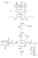
- Fig. 1 shows in outline the typical construction of existing cable television networks.
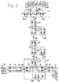
- Fig. 2 shows in outline a system for implementing the method according to the invention.
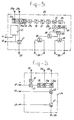
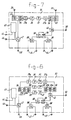
- Figs. 3, 4, 5, 6, 7 and 8 show in outline embodiments of amplifiers for use in a system for implementing the method according to the invention.
- Fig. 1 shows in outline a typical construction of a cable television network for the distribution of broadcasting signals, such as radio and television programmes and other information signals which are received or supplied in a receiver or head-end station 1.
- broadcasting signals such as radio and television programmes and other information signals which are received or supplied in a receiver or head-end station 1.
- receiving and conversion means 2 are set up in the head-end station 1 for receiving signals transmitted by terrestrial transmitters
- receiving and conversion means 3 are set up for receiving signals transmitted from satellite transmitters
- receiving and conversion means 4 are set up for distribution of, for example, radio and television programmes and other services provided by cable or otherwise, for example from a local studio.
- the converted signals are merged in the head-end station 1 by means of a coupling field 5, for distribution of the signals concerned via a cable network to individual terminals 7 and 8.
- the cable network which is generally composed of coaxial cable, can be subdivided into a main or trunk network 9a, b, c, d, e connected to the head-end station 1, and a distribution or district network 10a, b, c connected thereto.
- the terminals 7, 8 are linked to the district network by a drop network 11a and b.
- the signal to be distributed emanating from the coupling field 5, is fed to an amplifier 6 and is then distributed over a plurality of sections of the trunk network.
- Each section 9a, b, c, d, e comprises a plurality of trunk amplifiers 12, connected in cascade.
- the cable length between two next trunk amplifiers 12 can amount to from 500 to 600 metres.
- a district centre 13 is located for distribution of the signal to the terminals 7, 8 via the district network.
- distribution of signals, a characteristic of cable television networks, is likewise only indicated in outline by means of trunk network sections 9d, 9e.
- the signals are distributed from the district amplifier(s) and possible converters located in the district centre 13, either directly or via one or more group amplifiers 14 to the drop networks in the district network.
- an output amplifier may be connected for supplying the distributed signals at the desired level to the terminals 7, 8.
- One or more group amplifiers 14 and output amplifiers 15 can in turn be incorporated in the district network, the maximum cable length between two next amplifiers amounting to approximately 100 to 300 metres.
- a group amplifier 14 is shown only in the district network section 10b.
- Drop network section 11a forms a so-called mini-star section
- drop network section 11b is shown as a so-called branching network section.
- the individual terminals 7 are connected in cascade via branching elements 16.
- the branching elements 16 are constructed in such a way that as equal a signal level as possible is provided on terminal 7, independent of the position in the branching network.
- the drop network section 11a implemented as a mini-star network, comprises a so-called mini-star distribution element 17 by which the various terminals 8 are connected to the district network in star formation.
- trunk networks constructed in ring formation are also applied in practice.
- Star trunk networks are advantageous in areas with ribbon developments, whilst ring networks can be applied in extensive cable television networks in which the subscriber terminals are located relatively closely to each other.
- signals in and below the UHF television frequency band are distributed on the trunk network 9a, b, c, d, e in accordance with the VHF/UHF split band principle or in VHF/UHF broad band.
- Amplifier cascading is characteristic for cable television networks.
- a minimum signal level at the amplifier input of 73 dB ⁇ V and a maximum output level in the VHF frequency band of approximately 100 dB ⁇ V and in the UHF frequency band approximately 115 dB ⁇ V are normally used.
- AM television signals and FM radio signals can be distributed with acceptable signal/noise and intermodulation levels, based on these input and output signal levels.
- Cable lengths in the order of magnitude of 500 metres between two next amplifiers can be bridged in the trunk network using the so-called coax-3 cable which has an attenuation of approximately 3 dB per 100 m in the VHF frequency band at 230 MHz and an attenuation of approximately 6 dB in the UHF frequency band at 860 MHz.
- This distance between the amplifiers is limited in the district networks to 100 to 300 metres owing to the distribution over a plurality of directions necessary downstream the amplifiers.
- Fig. 2 shows an outline of a system constructed according to the invention, in which exponentially modulated television signals are distributed at frequencies above the UHF television frequency band instead of television signals in amplitude modulated form.
- the components of the existing cable television network are indicated with the same reference numbers as in fig. 1.
- a further coupling field 18 is provided in the head-end station 1 for distributing television signals supplied at frequencies above the UHF television frequency band.
- the coupling field 18 is set up for distributing frequency modulated (FM) television channels in a 950-1750 MHz frequency band. Since this modulation and frequency band correspond to the modulation method and intermediate frequency band used for television transmission via communication and broadcasting satellites, it is possible to distribute the signals emitted by the Low Noise Converter (LNC) in the satellite receiver aerial directly via the cable network, as represented in outline by the direct connection of the satellite aerial output, if necessary via a filter 19, to the coupling field 18.
- LNC Low Noise Converter
- the signals emanating from coupling fields 5 and 18 are separately amplified for distribution over the cable network using frequency split band techniques.
- an amplifier 20, for amplification of the signals at frequencies above the UHF television frequency band, and filters 21, 22 are added in the head-end station 1.
- the filters 21 are set up to transmit signals with frequencies below 860 MHz, while the filters 22 are constructed to transmit signals above 950 MHz.
- combined signals are produced for distribution via the trunk network, in this case sections 9a, b, c of this network.
- VHF/UHF television frequency bands As is conventional in VHF/UHF split band networks, is not represented in detail.
- the existing trunk amplifiers 12, the group amplifier 14 and the output amplifiers 15 in the district network therefore represent either VHF/UHF broadband or else VHF/UHF split band amplifiers.
- the two amplifiers 23 and 24 each contain first filter means 25 to transmit frequencies at or below the UHF television frequency band, in the preferred embodiment of the invention frequencies below 860 MHz, and second filter means 26 to transmit signals at frequencies above the UHF television frequency band, in this case the superband from 950 MHz and higher, for example.
- Amplification means 27, suitable for amplification of signal frequencies above the UHF television frequency band, are connected in series to the second filter means 26.
- the amplification means 27 are connected downstream of the second filter means 26 in the first or distribution amplifier 23, so that the first and second filter means 25, 26 are linked on their input sides and form an input 28 of the distribution amplifier 23.
- the output side of the second filter means 25 forms a first output 29, while the output from amplifier 27, which can be of multiple design if desired, forms one or more second output(s) 30 of the distribution amplifier 23.
- the two filter means 26 are connected downstream of the amplification means 27 in the case of the second or post-amplifier 24.
- the output sides of the first and second filter means 25, 26 form an output 33 of the post-amplifier, whilst the input side of the first filter means 25 forms a first input 31, and the input side of the amplification means 27 forms a second input 32 of the amplifier 24.
- the first and second filter means are preferably combined as much as possible into one filter, as represented in fig. 5-8 by the frame encircling the filter means.
- the lower band concerned cannot of course be used independently for signal distribution.
- this method limits the total capacity of the cable television network reference can nevertheless be made to capacity expansion on the trunk network without the need for supplementary optical fibre cables.
- amplifiers shown in fig. 3 and 4 were assembled during a practical test from components commercially available per se, amplifiers as shown in figure 5 and 6 have been designed based on measurement results.
- Fig. 5 shows a proposal for a distribution amplifier 23 corresponding to fig. 3 in block diagram form, in which the amplification means 27 are composed of three cascade-connected amplification stages 27a, 27b and 27c, with an equaliser 36 and an adjustable attenuator 37 in between.
- the first and second filter means 25, 26 are combined into one single filter, in which the first filter means 25 are split into a part 25a for transmitting the VHF frequency band and a part 25b for transmitting the UHF television frequency band. This of course gives rise to a first amplifier output 29 split into two parts, 29a and 29b respectively.
- This relates to a preferred embodiment for VHF/UHF split band cable television networks.
- VHF/UHF split band cable television networks By combining all of the frequency splits in one filter the effect of additional transmission attenuation is limited as a consequence of the additional filtering according to the invention.
- the first filter means 25 are naturally not split into two parts and there is of course only one first amplifier output 29.
- a so-called pilot tone branch element 40 is introduced downstream of the third amplification stage 27b for detection of a pilot tone signal transmitted over the cable television network, for example a pilot tone signal at a frequency between 1750-1800 MHz.
- the signal from the branch element 40 is transmitted via a small band filter 41 and an amplifier 42 connected downstream to a further adjustable attenuator 43 connected between the second and third amplification stage 27b, 27c.
- a control signal which is used to hold the pilot tone signal at a pre-determined level at the distribution amplifier outputs 30, is fed to the attenuator 43. If transmission takes place at frequencies above the satellite intermediate frequency band or generally when the frequency band to be transmitted comprises multiple octaves, it may be necessary to employ further pilot tones at higher frequencies.
- the signal level present downstream of the second amplification stage 27b is sufficient to cope with the margin required for control and smoothing.
- the controlled and smoothed signal is amplified in the third amplification stage 27c to provide a signal sufficiently strong to be fed to the two-way splitters 38.
- the number of four amplifier outputs 30 is sufficient for application on most trunk networks.
- a rectifier circuit 45 which can be externally fed if required via a connection terminal 46, is incorporated in the distribution amplifier 23.
- a current injection filter 47 in series with the distribution amplifier 23 input 28 is further incorporated for powering the cable television network itself.
- the VHF and/or UHF amplifiers 12, 14, 15 already incorporated in the network can likewise be fed via the current injection filter 47. Alternating voltage is moreover available on terminal 44 for powering one or more post-amplifiers 24.
- Fig. 6 shows an embodiment of the amplifier 24 shown in fig. 4 in which the first and second filter means 25, 26 are combined in one "merging filter".
- the first and second filter means 25 are split into a VHF section and a UHF section, 25a and 25b respectively, corresponding to the amplifier embodiment according to fig. 5.
- the two first amplifier inputs 31a and 31b may also consist of one single first input 31 for use in VHF/UHF broadband cable television networks.
- This post-amplifier 24 is relatively simple in construction and has only one single amplification stage 27 with adjustable attenuator 37.
- the post-amplifier 24 is fed with direct voltage via a connection terminal 48 and the supply voltage for the further, downstream, section of the network may be connected to a connection terminal 49. Connection terminal 50 forms a measurement point.
- the filter means may be accomplished in a way which is known per se in practice, like the amplification means and the remaining components mentioned.
- the output amplifier 51 is based on the distribution amplifier 23. Because of the lower amplification required, amplification stage 27c may be omitted. Since only one output amplifier is incorporated in the entire cascade, automatic gain control may also be omitted.
- the VHF and UHF bands are not split further since the existing output amplifiers 15 operate with one overall input both in the VHF/UHF split band and in VHF/UHF broadband systems.
- filter means 55 and 56 which correspond to filter means 25 and 26, are now also connected to the output of the second amplification stage 27b with a further input 53 for merging the signals amplified by the VHF/UHF output amplifier 15 and amplification stages 27a, b already present.
- a combined VHF/UHF superband signal is now available at the outputs 54 for powering the terminals 7, 8 of the cable television network.
- the mini-star amplifier 52 is likewise derived from the distribution amplifier 23. Since cable lengths between the group amplifier and the mini-star distribution element are kept to a limit in networks with passive mini-star distribution elements, in which no output amplifiers for the VHF and UHF television bands are applied prior to the mini-star distribution elements 17, a relatively low gain is sufficient in the mini-star distribution point for transmitting the superband through. In order to be able to satisfy the requirements with respect to relative signal levels on terminal 8, there is often a requirement in the case of passive mini-star distribution elements to be able to attenuate or smooth the signals in the VHF and UHF television frequency bands. For this purpose supplementary means for smoothing and distribution in the VHF and UHF television frequency bands are incorporated in the proposed mini-star amplifier.
- Table I relates to a UHF/VHF split band cable television network in which the trunk network is suitable only for transmission in the VHF band.
- Table II represents a VHF/UHF broad band cable television network, with signal distribution in the VHF band only on the trunk network.
- Table III relates to an advanced cable television network in which the trunk network as well as the district and drop networks are suitable for signal distribution in the VHF and UHF television frequency bands. This is indicated in the table as CAI-plus.
- the signal levels between 44 and 60 dB ⁇ V achieved on the terminals are more than sufficiently above the threshold levels of present satellite receivers which are of the order of magnitude of 35 dB ⁇ V.
- Table IV shows a possible channel grouping (allocation) of the superband according to the invention, based on a channel interval of 29.5 MHz.
- This channel bandwidth corresponds to the channel bandwidth which is used by currently popular satellites and for which a large variety of consumer equipment is available.
- the allocation plan is divided into a first band to 1450 MHz, to be used for a first capacity expansion, a second band from 1450 to 1750 MHz, a location for a pilot tone (1752 MHz) and a third band to 2050 MHz.
- an overall expansion of the cable television network can be accomplished by 37 PAL or MAC channels, the PAL channels each having a good eight extra sound channels available to them in accordance with the standard agreed for satellite programmes.
- Expansion of the channel capacity of the existing cable television network in accordance with the invention essentially requires no other adjustments other than installing amplifiers for amplification of the exponentially modulated television signals and of course setting up suitable equipment in the head-end station.
- the invention is of course not limited to the illustrative embodiments discussed above. To summarise, the invention makes possible the expansion of the channel capacity of all existing cable television networks, to 100 or more channels, in a relatively inexpensive and simple manner, and is suited to distribution of both analog and digital (broadcasting) signals.
Landscapes
- Engineering & Computer Science (AREA)
- Multimedia (AREA)
- Signal Processing (AREA)
- Physics & Mathematics (AREA)
- Astronomy & Astrophysics (AREA)
- General Physics & Mathematics (AREA)
- Details Of Television Systems (AREA)
- Two-Way Televisions, Distribution Of Moving Picture Or The Like (AREA)
Applications Claiming Priority (2)
| Application Number | Priority Date | Filing Date | Title |
|---|---|---|---|
| NL9201633A NL9201633A (nl) | 1992-09-21 | 1992-09-21 | Werkwijze en middelen voor signaaldistributie via een kabeltelevisienet. |
| NL9201633 | 1992-09-21 |
Publications (2)
| Publication Number | Publication Date |
|---|---|
| EP0589531A2 true EP0589531A2 (de) | 1994-03-30 |
| EP0589531A3 EP0589531A3 (de) | 1994-04-13 |
Family
ID=19861284
Family Applications (1)
| Application Number | Title | Priority Date | Filing Date |
|---|---|---|---|
| EP19930202724 Withdrawn EP0589531A3 (de) | 1992-09-21 | 1993-09-20 | Verfahren und Anlage zur Verteilung von Signalen mittels eines Kabelfernsehnetzwerkes |
Country Status (2)
| Country | Link |
|---|---|
| EP (1) | EP0589531A3 (de) |
| NL (1) | NL9201633A (de) |
Cited By (8)
| Publication number | Priority date | Publication date | Assignee | Title |
|---|---|---|---|---|
| EP0914012A3 (de) * | 1997-10-28 | 2000-11-29 | Alcatel | Vorrichtung zum Zusammenführen und Verstärken von zwei breitbandigen Signalen |
| US7138886B2 (en) | 2002-05-02 | 2006-11-21 | Xtend Networks Ltd. | Wideband CATV signal splitter device |
| US7209497B2 (en) | 2001-11-26 | 2007-04-24 | Xtend Networks Ltd. | System and method for spectral node splitting in a hybrid fiber optic-coaxial cable network |
| EP1342372B1 (de) * | 2000-10-16 | 2007-06-20 | Xtend Networks Ltd. | System und verfahren zur erweiterung der operativen bandbreite eines übertragungssystems |
| US7616890B2 (en) | 2000-10-16 | 2009-11-10 | Xtend Networks Ltd. | System, device and method of expanding the operational bandwidth of a communication infrastructure |
| US7716711B1 (en) | 1999-08-01 | 2010-05-11 | Xtend Networks Ltd. | Television multiplexing and transmission system and method |
| US7748023B2 (en) | 2001-02-27 | 2010-06-29 | Xtend Networks Ltd. | Device, system and method for connecting a subscriber device to a wideband distribution network |
| US7904932B2 (en) | 2000-10-16 | 2011-03-08 | Xtend Networks Ltd. | Wideband node in a CATV network |
Family Cites Families (1)
| Publication number | Priority date | Publication date | Assignee | Title |
|---|---|---|---|---|
| FR2662895B1 (fr) * | 1990-05-29 | 1992-08-28 | Telediffusion Fse | Installation de distribution de programmes de radiodiffusion a reseau cable. |
-
1992
- 1992-09-21 NL NL9201633A patent/NL9201633A/nl not_active Application Discontinuation
-
1993
- 1993-09-20 EP EP19930202724 patent/EP0589531A3/de not_active Withdrawn
Cited By (8)
| Publication number | Priority date | Publication date | Assignee | Title |
|---|---|---|---|---|
| EP0914012A3 (de) * | 1997-10-28 | 2000-11-29 | Alcatel | Vorrichtung zum Zusammenführen und Verstärken von zwei breitbandigen Signalen |
| US7716711B1 (en) | 1999-08-01 | 2010-05-11 | Xtend Networks Ltd. | Television multiplexing and transmission system and method |
| EP1342372B1 (de) * | 2000-10-16 | 2007-06-20 | Xtend Networks Ltd. | System und verfahren zur erweiterung der operativen bandbreite eines übertragungssystems |
| US7616890B2 (en) | 2000-10-16 | 2009-11-10 | Xtend Networks Ltd. | System, device and method of expanding the operational bandwidth of a communication infrastructure |
| US7904932B2 (en) | 2000-10-16 | 2011-03-08 | Xtend Networks Ltd. | Wideband node in a CATV network |
| US7748023B2 (en) | 2001-02-27 | 2010-06-29 | Xtend Networks Ltd. | Device, system and method for connecting a subscriber device to a wideband distribution network |
| US7209497B2 (en) | 2001-11-26 | 2007-04-24 | Xtend Networks Ltd. | System and method for spectral node splitting in a hybrid fiber optic-coaxial cable network |
| US7138886B2 (en) | 2002-05-02 | 2006-11-21 | Xtend Networks Ltd. | Wideband CATV signal splitter device |
Also Published As
| Publication number | Publication date |
|---|---|
| NL9201633A (nl) | 1994-04-18 |
| EP0589531A3 (de) | 1994-04-13 |
Similar Documents
| Publication | Publication Date | Title |
|---|---|---|
| US5485630A (en) | Audio/video distribution system | |
| US6580905B1 (en) | System and method for controlling the level of signals output to transmission media in a distributed antenna network | |
| US5191459A (en) | Method and apparatus for transmitting broadband amplitude modulated radio frequency signals over optical links | |
| US5802173A (en) | Radiotelephony system | |
| US5153762A (en) | Method and apparatus for recovering AM channell signals distributed on an optical fiber | |
| US6353490B1 (en) | C/N performance of broadband two-way transmission of RF signals over transmission mediums with limited bandwidth | |
| US20080040764A1 (en) | System, apparatus and method for expanding the operational bandwidth of a communication system | |
| US20020174435A1 (en) | System, apparatus and method for expanding the operational bandwidth of a communication system | |
| WO2002033969A1 (en) | System and method for expanding the operational bandwidth of a communication system | |
| US20110122928A1 (en) | High frequency signal hub | |
| US4475242A (en) | Microwave communications system | |
| EP0589531A2 (de) | Verfahren und Anlage zur Verteilung von Signalen mittels eines Kabelfernsehnetzwerkes | |
| US7903598B2 (en) | Apparatus and method for downstream power management in a cable system | |
| EP0707757B1 (de) | Mikrowellenübertragungssystem | |
| EP1342372B1 (de) | System und verfahren zur erweiterung der operativen bandbreite eines übertragungssystems | |
| US20260019093A1 (en) | Rf broadband amplifier station with distributed control system | |
| EP0735768A1 (de) | Lichtwellenleiter-Videonetzwerkarchitektur mit verteilten Videoquellen | |
| KR100642249B1 (ko) | 광동축혼합망을 이용한 절감형 디지털 멀티미디어방송시스템 | |
| JP4700337B2 (ja) | 共聴システム及びそのための装置 | |
| NL1031482C2 (nl) | Kabeltelevisiesysteem met uitgebreide kwadratuuramplitudemodulatiesignaaluitwisseling, zendmiddelen en een beheercentrum daarvoor. | |
| JPH07107328A (ja) | 共同聴視施設及び分岐増幅装置 | |
| Young | RFMD.® | |
| KR200297875Y1 (ko) | 무손실 위성신호 분배장치 | |
| RU2457633C1 (ru) | Система коллективного приема телевизионных сигналов с различными типами модуляции | |
| JP2001231023A (ja) | 双方向catvシステム |
Legal Events
| Date | Code | Title | Description |
|---|---|---|---|
| PUAI | Public reference made under article 153(3) epc to a published international application that has entered the european phase |
Free format text: ORIGINAL CODE: 0009012 |
|
| PUAL | Search report despatched |
Free format text: ORIGINAL CODE: 0009013 |
|
| AK | Designated contracting states |
Kind code of ref document: A2 Designated state(s): AT BE CH DE DK ES FR GB GR IE IT LI LU MC NL PT SE |
|
| AK | Designated contracting states |
Kind code of ref document: A3 Designated state(s): AT BE CH DE DK ES FR GB GR IE IT LI LU MC NL PT SE |
|
| 17P | Request for examination filed |
Effective date: 19940830 |
|
| 17Q | First examination report despatched |
Effective date: 19960820 |
|
| 18D | Application deemed to be withdrawn |
Effective date: 19971228 |