EP0589570A1 - Verdichter - Google Patents
Verdichter Download PDFInfo
- Publication number
- EP0589570A1 EP0589570A1 EP93306779A EP93306779A EP0589570A1 EP 0589570 A1 EP0589570 A1 EP 0589570A1 EP 93306779 A EP93306779 A EP 93306779A EP 93306779 A EP93306779 A EP 93306779A EP 0589570 A1 EP0589570 A1 EP 0589570A1
- Authority
- EP
- European Patent Office
- Prior art keywords
- sealed casing
- line segment
- compressor
- plane
- compressing
- Prior art date
- Legal status (The legal status is an assumption and is not a legal conclusion. Google has not performed a legal analysis and makes no representation as to the accuracy of the status listed.)
- Granted
Links
- 239000003507 refrigerant Substances 0.000 claims abstract description 32
- 230000006698 induction Effects 0.000 claims abstract description 21
- 239000000314 lubricant Substances 0.000 claims description 10
- 230000005484 gravity Effects 0.000 claims description 8
- 230000004048 modification Effects 0.000 description 28
- 238000012986 modification Methods 0.000 description 28
- 230000010349 pulsation Effects 0.000 description 7
- 230000000694 effects Effects 0.000 description 5
- LVGUZGTVOIAKKC-UHFFFAOYSA-N 1,1,1,2-tetrafluoroethane Chemical compound FCC(F)(F)F LVGUZGTVOIAKKC-UHFFFAOYSA-N 0.000 description 3
- 238000002474 experimental method Methods 0.000 description 3
- 239000010687 lubricating oil Substances 0.000 description 3
- 238000004458 analytical method Methods 0.000 description 2
- 230000008878 coupling Effects 0.000 description 2
- 238000010168 coupling process Methods 0.000 description 2
- 238000005859 coupling reaction Methods 0.000 description 2
- 239000003921 oil Substances 0.000 description 2
- 238000005057 refrigeration Methods 0.000 description 2
- 230000006835 compression Effects 0.000 description 1
- 238000007906 compression Methods 0.000 description 1
- 230000002708 enhancing effect Effects 0.000 description 1
- 230000007613 environmental effect Effects 0.000 description 1
Images


Classifications
-
- F—MECHANICAL ENGINEERING; LIGHTING; HEATING; WEAPONS; BLASTING
- F04—POSITIVE - DISPLACEMENT MACHINES FOR LIQUIDS; PUMPS FOR LIQUIDS OR ELASTIC FLUIDS
- F04B—POSITIVE-DISPLACEMENT MACHINES FOR LIQUIDS; PUMPS
- F04B39/00—Component parts, details, or accessories, of pumps or pumping systems specially adapted for elastic fluids, not otherwise provided for in, or of interest apart from, groups F04B25/00 - F04B37/00
- F04B39/12—Casings; Cylinders; Cylinder heads; Fluid connections
- F04B39/121—Casings
-
- F—MECHANICAL ENGINEERING; LIGHTING; HEATING; WEAPONS; BLASTING
- F04—POSITIVE - DISPLACEMENT MACHINES FOR LIQUIDS; PUMPS FOR LIQUIDS OR ELASTIC FLUIDS
- F04B—POSITIVE-DISPLACEMENT MACHINES FOR LIQUIDS; PUMPS
- F04B39/00—Component parts, details, or accessories, of pumps or pumping systems specially adapted for elastic fluids, not otherwise provided for in, or of interest apart from, groups F04B25/00 - F04B37/00
- F04B39/0027—Pulsation and noise damping means
- F04B39/0055—Pulsation and noise damping means with a special shape of fluid passage, e.g. bends, throttles, diameter changes, pipes
-
- Y—GENERAL TAGGING OF NEW TECHNOLOGICAL DEVELOPMENTS; GENERAL TAGGING OF CROSS-SECTIONAL TECHNOLOGIES SPANNING OVER SEVERAL SECTIONS OF THE IPC; TECHNICAL SUBJECTS COVERED BY FORMER USPC CROSS-REFERENCE ART COLLECTIONS [XRACs] AND DIGESTS
- Y10—TECHNICAL SUBJECTS COVERED BY FORMER USPC
- Y10S—TECHNICAL SUBJECTS COVERED BY FORMER USPC CROSS-REFERENCE ART COLLECTIONS [XRACs] AND DIGESTS
- Y10S181/00—Acoustics
- Y10S181/403—Refrigerator compresssor muffler
Definitions
- the present invention relates generally to a compressor or a closed-type compressor for use in, such as, a refrigerator.
- hermetic compressors with reduced noise have been largely demanded in view of the environmental amenity.
- a hermetic compressor having a hermetic or sealed casing of such a shape as to prevent generation of a resonance sound in the sealed casing as disclosed such as in Japanese Second (examined) Patent Publication No. 3-53476.
- the proposed conventional sealed casing has a shape such that a straight line drawn from any portion of its inner wall at a right angle intersects with an opposite portion of the inner wall at an angle other than the right angle.
- This structure serves to prevent generation of resonance in the sealed casing since an acoustic or sound wave reflected by the opposite inner wall portion does not return to the portion where it comes from. Accordingly, this structure serves to prevent increment of the noise which would be otherwise caused by the resonance in the sealed casing, so as to provide the hermetic compressor with reduced noise.
- the effect for preventing the generation of resonance in the sealed casing becomes larger.
- a shape of the sealed casing has to be distorted unnaturally.
- the sealed casing is weakened in strength, which causes increment of the noise caused by vibration of the sealed casing.
- the shape of the sealed casing is forced to be distorted in view of reducing the resonance noise, the space in the sealed casing can not be effectively utilized in comparison with a sealed casing having a normal shape.
- the sealed casing undesirably increases in size for accommodating therein a compressing unit and a driving unit which drives the compressing unit.
- the present invention aims to provide an improved hermetic compressor with reduced noise that can eliminate the foregoing disadvantages inherent in the conventional hermetic compressors.
- compressor comprises a sealed casing which stores lubricant therein at its lower part; compressing means, provided in the sealed casing, for compressing a refrigerant; driving means, provided in the sealed casing, for driving the compressing means; and induction means for introducing the refrigerant into the compressing means, the induction means having a first end communicating with the compressing means and a second end which is opened to space in the sealed casing at a position on a first plane intersecting with a first line segment at its middle point and in perpendicular thereto, the first line segment having a minimum length among lengths of line segments each extending between arbitrary two points on an internal wall of the sealed casing at a level of a horizontal section of the interior of the sealed casing via a center of gravity of the horizontal section, the horizontal section having a maximum area over a vertical length of the sealed casing.
- a compressor comprises a sealed casing which stores lubricant therein at its lower part; compressing means, provided in the sealed casing, for compressing a refrigerant; driving means, provided in the sealed casing, for driving the compressing means; and induction means for introducing the refrigerant into the compressing means, the induction means having a first end communicating with the compressing means and a second end which is opened to space in the sealed casing at a position on a first plane intersecting with a first line segment at its middle point and in perpendicular thereto.
- the first line segment extending between arbitrary two points on an internal wall of the sealed casing and in perpendicular to a second line segment on a horizontal plane including the second line segment, the second line segment having a minimum length among lengths of line segments each extending between arbitrary two points on the internal wall of the sealed casing at a level of a horizontal section of the interior of the sealed casing via a center of gravity of the horizontal section, the horizontal section having a maximum area over a vertical length of the sealed casing.
- a compressor comprises a sealed casing which stores lubricant therein at its lower part; compressing means, provided in the sealed casing, for compressing a refrigerant; driving means, provided in the sealed casing, for driving the compressing means; and induction means for introducing the refrigerant into the compressing means, the induction means having a first end communicating with the compressing means and a second end which is opened to space in the sealed casing at a position on a first plane intersecting with a first line segment at its middle point and in perpendicular thereto, the first line segment having a maximum length among lengths of line segments each extending vertically between an arbitrary upper point on an internal wall of the sealed casing and a level of the lubricant in the sealed casing.
- a compressor comprises a sealed casing which stores lubricant therein at its lower part; compressing means, provided in the sealed casing. for compressing a refrigerant; driving means, provided in the sealed casing, for driving the compressing means; and induction means for introducing the refrigerant into the compressing means, the induction means having a first end communicating with the compressing means and a second end which is opened to space in the sealed casing at a position corresponding to a node of a standing wave of the refrigerant in the sealed casing, the standing wave being generated due to operation of the compressing means via the induction means.
- the compressor may be hermetically sealed or a hermetic compressor.
- Advantageously lubricant may be stored in a lower region of the casing.
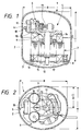
- Figs. 1 and 2 respectively show a hermetic compressor 1 according to a first preferred embodiment of the present invention, wherein Fig. 1 is a longitudinal or vertical sectional view of the hermetic compressor 1, and Fig. 2 is a cross-sectional or horizontal sectional view of the hermetic compressor 1 with components in a hermetic or sealed casing 2 being illustrated in a top plan view.
- the sealed casing 2 is formed by a lower casing member 3 and an upper casing member 4 which are firmly fixed to each other.
- the interior or the interior space of the sealed casing 2 has an oval shape or a substantially elliptic shape in horizontal section.
- numeral 5 designates a driving-compressing unit which is resiliently supported by coil springs 8.
- the driving-compressing unit 5 includes a compressing unit 6 and a driving unit 7.
- the compressing unit 6 includes, such as, a cylinder 10 formed integral with a base block 9, a piston 11, a crankshaft 12, a connecting rod 13 and a bearing 14.
- the driving unit 7 includes a rotor 15 and a stator 16 to form a motor.
- the rotor 15 is fixed to the crankshaft 12 by shrinkage fitting, and the stator 16 is fixed to the base block 9 by screws.
- Numeral 17 represents lubricating oil stored in the sealed casing 2 at its lower part.
- Letter A represents a minimum horizontal distance among horizontal distances each measured between arbitrary two opposite points on an internal wall of the sealed casing 2 at a level of a certain horizontal section of the interior of the sealed casing 2, via a center of gravity of such a horizontal section.
- this horizontal section is selected so as to have a maximum area over the height or the vertical length of the sealed casing 2, i.e. an area of this horizontal section being maximum among areas of horizontal sections of the interior of the sealed casing 2 over the vertical length of the sealed casing 2.
- the interior of the sealed casing 2 is defined by the above-noted internal wall of the sealed casing 2.
- A represents a minimum length among lengths of line segments each extending between arbitrary two opposite points on the internal wall of the sealed casing 2 at the level of the above-noted horizontal section via the center of gravity thereof.
- A represents a maximum distance among distances each measured between arbitrary two opposite points on the internal wall of the sealed casing 2 in a direction perpendicular to directions of the reciprocating motion of the piston 11 as well as to an axial direction of the crankshaft 12.
- Letter B represents a maximum horizontal distance among horizontal distances each between arbitrary two opposite points on the internal wall of the sealed casing 2, as measured in a direction perpendicular to the line segment having the above-noted minimum length A (hereinafter referred to as "minimum length line segment A”) on a horizontal plane including this minimum length line segment A, i.e. at the level of the above-noted certain horizontal section of the interior of the sealed casing 2.
- B represents a maximum length among lengths of line segments each extending between arbitrary two opposite points on the internal wall of the sealed casing 2. as measured in a direction perpendicular to the minimum length line segment A on a horizontal plane including this minimum length line segment A, i.e.
- B represents a maximum distance among distances each between arbitrary two opposite points on the internal wall of the sealed casing 2, as measured in the directions of the reciprocating motion of the piston 11.
- Letter C represents a maximum vertical distance among vertical distances each measured between an arbitrary upper point on the internal wall of the sealed casing 2 and an oil level of the lubricating oil 17 in the sealed casing 2.
- C represents a maximum length among lengths of line segments each extending between an arbitrary upper point on the internal wall of the sealed casing 2 and an oil level of the lubricating oil 17 in the sealed casing 2.
- Numeral 18 designates a suction or induction pipe which is fixed to the base block 9 and communicates with the interior of the cylinder 10 at its one end working as an outlet.
- the suction pipe 18 has the other end, working as an inlet, which is opened to space or room in the sealed casing 2 at a position on a certain plane. This plane intersects with the minimum length line segment A at a middle point thereof and in perpendicular thereto, as clearly shown in Fig. 2.
- a refrigerant which has been circulated through a refrigeration system of, such as, the refrigerator is introduced to the interior of the sealed casing 2 in a known manner.
- the introduced refrigerant is then sucked into the cylinder 10 via the suction pipe 18 and pressurized or compressed due to the reciprocating motion of the piston 11.
- the refrigerant is sucked into the cylinder 10 during a half (1/2) rotation of the crankshaft 12, and is pressurized during a subsequent half (1/2) rotation of the crankshaft 12. Accordingly, since the refrigerant is not sucked into the cylinder 10 in a continuous manner, pressure pulsation of the refrigerant is generated at the suction pipe 18.
- This pressure pulsation excites the space to cause vibration in the sealed casing 2 so that the compressor 1 has possible resonance modes in directions of the reciprocating motion of the piston 11 and in directions perpendicular to the directions of the reciprocating motion of the piston 11, wherein each of "resonance modes" represents a state of the compressor 1 corresponding to one of the possible resonance frequencies of the compressor 1.
- a resonance frequency of the resonance mode of the compressor 1 in the direction of the minimum length line segment A (hereinafter referred to as "direction A") becomes 585Hz which corresponds to a frequency of a pressure pulsation component of the refrigerant (HFC-134a) in the direction A, i.e. a frequency of a standing wave of the refrigerant in the direction A.
- the frequency of 585Hz is an integral multiple of a rotational frequency of the driving unit 7 as operated at 50Hz.
- the suction pipe 18 has the open end or opening at the position on the plane which intersects with the minimum length line segment A at its middle point and in perpendicular thereto.
- the suction pipe 18 is opened at a position corresponding to a node of the standing wave in the direction A, i.e. at a position on a vertical plane defined by the node of the standing wave in the direction A.
- the pressure pulsation component of the refrigerant applies vibration at the node of the standing wave in the direction A so that the generation of the resonance is effectively suppressed.
- a sound of 585Hz representing the resonance sound is reduced by more than 10dB by positioning the opening of the suction pipe 18 as described above. This means that increment of the noise of the compressor 1, which would be otherwise caused due to the resonance sound, is effectively prevented in the first preferred embodiment.
- Fig. 3 is a horizontal sectional view of the hermetic compressor 1, as corresponding to Fig. 2, according to a first modification of the first preferred embodiment.
- the same or corresponding elements and dimensions are designated by the same references as those in Figs. 1 and 2 so as to avoid redundant disclosure.
- the dimensional relationship among the distances or lengths A, B and C is set such that the resonance mode of the compressor 1 is satisfied or activated in a direction of the line segment having the maximum length B (hereinafter referred to as "direction B").
- the suction pipe 18 has one end communicating with the interior of the cylinder 10 as in the first preferred embodiment, and the other end being opened at a position on a plane which intersects with the line segment having the maximum length B (hereinafter referred to as "maximum length line segment B”) at its middle point and in perpendicular thereto, or which intersects with any one of the line segments at its middle point and in perpendicular thereto, those line segments each extending between arbitrary two opposite points on the internal wall of the sealed casing 2 and in perpendicular to the minimum length line segment A on the horizontal plane.
- maximum length line segment B the line segment having the maximum length B
- the suction pipe 18 is opened at a position corresponding to a node of a standing wave in the direction B, i.e. at a position on a vertical plane defined by the node of the standing wave in the direction B.
- the first modification effectively works to suppress the generation of the resonance sound when the resonance mode of the compressor 1 in the direction B is satisfied, for the reason as described in the first preferred embodiment.
- the other structure of the first modification is substantially the same as that in the first preferred embodiment.
- Fig. 4 is a vertical sectional view of the hermetic compressor 1, as corresponding to Fig. 1, according to a second modification of the first preferred embodiment.
- the same or corresponding elements and dimensions are designated by the same references as those in Figs. 1 and 2 so as to avoid redundant disclosure.
- the dimensional relationship among the distances or lengths A, B and C is set such that the resonance mode of the compressor 1 is satisfied in a direction of the line segment having the maximum length C (hereinafter referred to as "direction C").
- the suction pipe 18 has one end communicating with the interior of the cylinder 10 as in the first preferred embodiment, and the other end being opened at a position on a plane which intersects with the line segment having the maximum length C (hereinafter referred to as "maximum length line segment C") at its middle point and in perpendicular thereto.
- maximum length line segment C the line segment having the maximum length C
- the suction pipe 18 is opened at a position corresponding to a node of a standing wave in the direction C, i.e. at a position on a horizontal plane defined by the node of the standing wave in the direction C.
- the second modification effectively works to suppress the generation of the resonance sound when the resonance mode of the compressor 1 in the direction C is satisfied, for the reason as described in the first preferred embodiment.
- the other structure of the second modification is substantially the same as that in the first preferred embodiment.
- Fig. 5 is a vertical sectional view of the compressor 1, as corresponding to Fig. 1
- Fig. 6 is a horizontal sectional view of the compressor 1, as corresponding to Fig. 2.
- Figs. 5 and 6 the same or corresponding elements and dimensions are designated by the same references as those in Figs. 1 and 2 so as to avoid redundant disclosure.
- the suction pipe 18 has one end communicating with the interior of the cylinder 10 as in the first preferred embodiment.
- the suction pipe 18 has the other end being opened at a position on a line of intersection between a plane which intersects with the minimum length line segment A at its middle point and in perpendicular thereto and a plane which intersects with the maximum length line segment C at its middle point and in perpendicular thereto. This means that the suction pipe 18 is opened at a position corresponding to a node of a standing wave in the direction A, i.e.
- a resonance frequency of the resonance mode of the compressor 1 in the direction A becomes 585Hz which corresponds to a frequency of a pressure pulsation component of the refrigerant (HFC-134a) in the direction A, i.e. a frequency of a standing wave in the direction A.
- the frequency of 585Hz is an integral multiple of a rotational frequency of the driving unit 7 as operated at 50Hz.
- a resonance frequency of the resonance mode of the compressor 1 in the direction C becomes 535Hz which corresponds to a frequency of a pressure pulsation component of the refrigerant (HFC-134a) in the direction C, i.e. a frequency of a standing wave in the direction C.
- the frequency of 535Hz is an integral multiple of the rotational frequency of the driving unit 7 as operated at 50Hz.
- the suction pipe 18 is opened at the position on the above-noted intersecting line formed by the intersection between the above-noted two planes. Accordingly, the pressure pulsation components of the refrigerant apply vibration at the nodes of the standing waves for both the resonance mode in the direction A and the resonance mode in the direction C so that the generation of the resonance sound is effectively suppressed. As a result, increment of the noise of the compressor 1, which would be otherwise caused due to the resonance sound, is effectively prevented in the second preferred embodiment even when the resonance modes of the compressor 1 in the directions both A and C are satisfied.
- the other structure of the second preferred embodiment is substantially the same as that in the first preferred embodiment.
- Figs. 7 and 8 show a first modification of the second preferred embodiment, and correspond to Figs. 5 and 6 of the second preferred embodiment, respectively.
- the same or corresponding elements and dimensions are designated by the same references as those in Figs. 5 and 6 so as to avoid redundant disclosure.
- the dimensional relationship among the distances or lengths A, B and C is set such that the resonance modes of the compressor 1 are satisfied in the directions B and C.
- the suction pipe 18 has one end communicating with the interior of the cylinder 10 as in the second preferred embodiment.
- the suction pipe 18 has the other end being opened at a position on a line of intersection between a plane which intersects with the maximum length line segment B at its middle point and in perpendicular thereto or which intersects with any one of the line segments at its middle point and in perpendicular thereto, those line segments each extending between arbitrary two opposite points on the internal wall of the sealed casing 2 and in perpendicular to the minimum length line segment A on the horizontal plane, and a plane which intersects with the maximum length line segment C at its middle point and in perpendicular thereto.
- the suction pipe 18 is opened at a position corresponding to a node of a standing wave in the direction B, i.e. at a position on a vertical plane defined by the node of the standing wave in the direction B, and simultaneously, at a position corresponding to a node of a standing wave in the direction C, i.e. at a position on a horizontal plane defined by the node of the standing wave in the direction C.
- the first modification of the second preferred embodiment effectively works to suppress the generation of the resonance sound when the resonance modes of the compressor 1 in the directions both B and C are satisfied, for the reason as described in the second preferred embodiment.
- the other structure of the first modification is substantially the same as that in the second preferred embodiment.
- Figs. 9 and 10 show a second modification of the second preferred embodiment, and correspond to Figs. 5 and 6 of the second preferred embodiment, respectively.
- the same or corresponding elements and dimensions are designated by the same references as those in Figs. 5 and 6 so as to avoid redundant disclosure.
- the dimensional relationship among the distances or lengths A, B and C is set such that the resonance modes of the compressor 1 are satisfied in the directions A and B.
- the suction pipe 18 has one end communicating with the interior of the cylinder 10 as in the second preferred embodiment.
- the suction pipe 18 has the other end being opened at a position on a line of intersection between a plane which intersects with the minimum length line segment A at its middle point and in perpendicular thereto and a plane which intersects with the maximum length line segment B at its middle point and in perpendicular thereto or which intersects with any one of the line segments at its middle point and in perpendicular thereto, those line segments each extending between arbitrary two opposite points on the internal wall of the sealed casing 2 and in perpendicular to the minimum length line segment A on the horizontal plane.
- the suction pipe 18 is opened at a position corresponding to a node of a standing wave in the direction A, i.e. at a position on a vertical plane defined by the node of the standing wave in the direction A, and simultaneously, at a position corresponding to a node of a standing wave in the direction B, i.e. at a position on a vertical plane defined by the node of the standing wave in the direction B.
- the second modification of the second preferred embodiment effectively works to suppress the generation of the resonance sound when the resonance modes of the compressor 1 in the directions both A and B are satisfied, for the reason as described in the second preferred embodiment.
- the other structure of the second modification is substantially the same as that in the second preferred embodiment.
- the suction pipe 18 has one end communicating with the interior of the cylinder 10 as in the second preferred embodiment.
- the suction pipe 18 has the other end being opened at a point of intersection among a plane which intersects with the minimum length line segment A at its middle point and in perpendicular thereto, a plane which intersects with the maximum length line segment B at its middle point and in perpendicular thereto or which intersects with any one of the line segments at its middle point and in perpendicular thereto, those line segments each extending between arbitrary two opposite points on the internal wall of the sealed casing 2 and in perpendicular to the minimum length line segment A on the horizontal plane, and a plane which intersects with the maximum length line segment C at its middle point and in perpendicular thereto.
- the suction pipe 18 is opened at a position corresponding to a node of a standing wave in the direction A, i.e. at a position on a vertical plane defined by the node of the standing wave in the direction A. and simultaneously, at a position corresponding to a node of a standing wave in the direction B, i.e. at a position on a vertical plane defined by the node of the standing wave in the direction B, and further simultaneously, at a position corresponding to a node of a standing wave in the direction C, i.e. at a position on a horizontal plane defined by the node of the standing wave in the direction C.
- This further modification of the second preferred embodiment effectively works to suppress the generation of the resonance sound when the resonance modes of the compressor 1 in the directions A, B and C are satisfied, for the reason as described in the second preferred embodiment.
- a muffler or the like when a muffler or the like is additionally provided at the suction pipe 18, similar effects may be realized by positioning an open end of the muffler as described in the first and second preferred embodiments and their modifications. Further, in a direct-suction-type compressor, similar effects may be realized by positioning a coupling portion between a suction pipe and a muffler as described in the first and second preferred embodiments and their modifications.
- the coupling portion is provided in the sealed casing using, such as, a spring for connection with a refrigeration system of, such as, the refrigerator.
- the present invention is applicable irrespective of a compression manner of the compressor or the number of the cylinders 10. Further, even when the suction pipes 18 are provided in number more than one, similar effects may be realized by arranging the opening of each suction pipe at the position on the foregoing plane or on the foregoing intersecting line or point.
Landscapes
- Engineering & Computer Science (AREA)
- Mechanical Engineering (AREA)
- General Engineering & Computer Science (AREA)
- Compressor (AREA)
- Applications Or Details Of Rotary Compressors (AREA)
Applications Claiming Priority (2)
| Application Number | Priority Date | Filing Date | Title |
|---|---|---|---|
| JP226932/92 | 1992-08-26 | ||
| JP4226932A JPH0674154A (ja) | 1992-08-26 | 1992-08-26 | 密閉型圧縮機 |
Publications (2)
| Publication Number | Publication Date |
|---|---|
| EP0589570A1 true EP0589570A1 (de) | 1994-03-30 |
| EP0589570B1 EP0589570B1 (de) | 1996-05-08 |
Family
ID=16852868
Family Applications (1)
| Application Number | Title | Priority Date | Filing Date |
|---|---|---|---|
| EP93306779A Expired - Lifetime EP0589570B1 (de) | 1992-08-26 | 1993-08-26 | Verdichter |
Country Status (4)
| Country | Link |
|---|---|
| US (1) | US5358386A (de) |
| EP (1) | EP0589570B1 (de) |
| JP (1) | JPH0674154A (de) |
| DE (1) | DE69302549T2 (de) |
Cited By (5)
| Publication number | Priority date | Publication date | Assignee | Title |
|---|---|---|---|---|
| EP0984162A4 (de) * | 1997-05-21 | 2001-04-11 | Matsushita Refrigeration | Umschlossener verdichter und kühlsystem |
| EP1158170A1 (de) * | 1994-04-28 | 2001-11-28 | Kabushiki Kaisha Toshiba | Verdichter |
| WO2009083359A1 (en) * | 2007-12-28 | 2009-07-09 | Arcelik Anonim Sirketi | A hermetic compressor |
| CN101487645B (zh) * | 2008-01-17 | 2012-07-18 | 思科普有限责任公司 | 制冷剂压缩机设备 |
| WO2020015900A1 (en) * | 2018-07-19 | 2020-01-23 | Arcelik Anonim Sirketi | An insulation cap |
Families Citing this family (6)
| Publication number | Priority date | Publication date | Assignee | Title |
|---|---|---|---|---|
| JP3173336B2 (ja) * | 1995-07-12 | 2001-06-04 | 日東紡績株式会社 | 高強度ロックウール及びその製造方法 |
| CN1519473A (zh) * | 1996-06-14 | 2004-08-11 | 松下冷机株式会社 | 封闭式压缩机 |
| US20020004113A1 (en) * | 1997-06-26 | 2002-01-10 | Weder Donald E. | Decorative cover for flower pot or floral grouping formed of polymeric materials having a texture or appearance simulating the texture or appearance of paper |
| US6102677A (en) * | 1997-10-21 | 2000-08-15 | Matsushita Electric Industrial Co., Ltd. | Hermetic compressor |
| DE102007060825A1 (de) | 2007-12-18 | 2009-06-25 | BSH Bosch und Siemens Hausgeräte GmbH | Linearverdichteraggregat |
| KR101457703B1 (ko) * | 2008-10-28 | 2014-11-04 | 엘지전자 주식회사 | 압축기 |
Citations (4)
| Publication number | Priority date | Publication date | Assignee | Title |
|---|---|---|---|---|
| GB2078311A (en) * | 1980-06-11 | 1982-01-06 | Tecumseh Products Co | Continuous curvature noise suppressing compressor housing |
| US4371319A (en) * | 1979-07-13 | 1983-02-01 | Hitachi, Ltd. | Hermetic motor compressor |
| GB2118256A (en) * | 1982-04-15 | 1983-10-26 | Necchi Spa | Compressor silencer |
| FR2594527A1 (fr) * | 1986-02-18 | 1987-08-21 | Danfoss As | Capsule pour petite machine frigorifique encapsulee hermetiquement |
Family Cites Families (8)
| Publication number | Priority date | Publication date | Assignee | Title |
|---|---|---|---|---|
| US3169696A (en) * | 1963-01-10 | 1965-02-16 | Whirlpool Co | Compressor lubrication means |
| US3279683A (en) * | 1964-09-21 | 1966-10-18 | American Motors Corp | Motor-compressor unit |
| JPS4918245A (de) * | 1972-06-08 | 1974-02-18 | ||
| US3876339A (en) * | 1973-08-06 | 1975-04-08 | Sundstrand Corp | Reciprocating piston gas compressor |
| US4431356A (en) * | 1974-11-14 | 1984-02-14 | Lassota Marek J | Hermetic refrigeration rotary motor-compressor |
| US4313715A (en) * | 1979-12-21 | 1982-02-02 | Tecumseh Products Company | Anti-slug suction muffler for hermetic refrigeration compressor |
| US4401418B1 (en) * | 1981-04-29 | 1998-01-06 | White Consolidated Ind Inc | Muffler system for refrigeration compressor |
| US4975066A (en) * | 1989-06-27 | 1990-12-04 | Amp Incorporated | Coaxial contact element |
-
1992
- 1992-08-26 JP JP4226932A patent/JPH0674154A/ja active Pending
-
1993
- 1993-08-25 US US08/112,179 patent/US5358386A/en not_active Expired - Lifetime
- 1993-08-26 DE DE69302549T patent/DE69302549T2/de not_active Expired - Lifetime
- 1993-08-26 EP EP93306779A patent/EP0589570B1/de not_active Expired - Lifetime
Patent Citations (4)
| Publication number | Priority date | Publication date | Assignee | Title |
|---|---|---|---|---|
| US4371319A (en) * | 1979-07-13 | 1983-02-01 | Hitachi, Ltd. | Hermetic motor compressor |
| GB2078311A (en) * | 1980-06-11 | 1982-01-06 | Tecumseh Products Co | Continuous curvature noise suppressing compressor housing |
| GB2118256A (en) * | 1982-04-15 | 1983-10-26 | Necchi Spa | Compressor silencer |
| FR2594527A1 (fr) * | 1986-02-18 | 1987-08-21 | Danfoss As | Capsule pour petite machine frigorifique encapsulee hermetiquement |
Cited By (5)
| Publication number | Priority date | Publication date | Assignee | Title |
|---|---|---|---|---|
| EP1158170A1 (de) * | 1994-04-28 | 2001-11-28 | Kabushiki Kaisha Toshiba | Verdichter |
| EP0984162A4 (de) * | 1997-05-21 | 2001-04-11 | Matsushita Refrigeration | Umschlossener verdichter und kühlsystem |
| WO2009083359A1 (en) * | 2007-12-28 | 2009-07-09 | Arcelik Anonim Sirketi | A hermetic compressor |
| CN101487645B (zh) * | 2008-01-17 | 2012-07-18 | 思科普有限责任公司 | 制冷剂压缩机设备 |
| WO2020015900A1 (en) * | 2018-07-19 | 2020-01-23 | Arcelik Anonim Sirketi | An insulation cap |
Also Published As
| Publication number | Publication date |
|---|---|
| US5358386A (en) | 1994-10-25 |
| DE69302549D1 (de) | 1996-06-13 |
| DE69302549T2 (de) | 1996-10-02 |
| JPH0674154A (ja) | 1994-03-15 |
| EP0589570B1 (de) | 1996-05-08 |
Similar Documents
| Publication | Publication Date | Title |
|---|---|---|
| KR100269951B1 (ko) | 압축기의 흡입 머플러 | |
| US20050129534A1 (en) | Hermetic compressor | |
| US20020006342A1 (en) | Discharge muffler of a hermetic rotary compressor | |
| US5358386A (en) | Hermetic compressor | |
| US6149402A (en) | Suction muffler for hermetic reciprocating compressor | |
| US5703336A (en) | Exhaust noise suppressing apparatus for hermetic compressor | |
| JP3464441B2 (ja) | 密閉型往復動式圧縮機 | |
| WO2001029419A1 (en) | Noise reduction device for use in a reciprocating compressor using a side-branch silencer | |
| JP4735084B2 (ja) | 密閉型圧縮機 | |
| JP2001317479A (ja) | 縦置型圧縮機 | |
| WO2002081916A8 (en) | Oil pumping system for a reciprocating hermetic compressor | |
| JP3130127B2 (ja) | 密閉型圧縮機 | |
| US5222877A (en) | Motor-compressor unit | |
| US6374943B1 (en) | Baffle plate of discharge muffler for hermetic reciprocating compressor | |
| US20040213682A1 (en) | Hermetic compressor | |
| JP3150440B2 (ja) | 密閉型圧縮機 | |
| KR100548858B1 (ko) | 밀폐형 압축기 및 그것을 이용한 냉장고 | |
| JP3220617B2 (ja) | 密閉型電動圧縮機 | |
| KR200165730Y1 (ko) | 압축기용 흡입머플러의 냉매흡입관 결합구조 | |
| EP0905377B1 (de) | Gegossener Saugeinlass | |
| GB2315300A (en) | Vibration suppression in a motor-driven compressor | |
| KR200168208Y1 (ko) | 밀폐형 압축기의 소음 감쇄장치 | |
| KR200141250Y1 (ko) | 밀폐형 압축기의 배관계구조 | |
| JP3040210B2 (ja) | 往復型圧縮機の吐出管 | |
| US20050053479A1 (en) | Compressor |
Legal Events
| Date | Code | Title | Description |
|---|---|---|---|
| PUAI | Public reference made under article 153(3) epc to a published international application that has entered the european phase |
Free format text: ORIGINAL CODE: 0009012 |
|
| 17P | Request for examination filed |
Effective date: 19930904 |
|
| AK | Designated contracting states |
Kind code of ref document: A1 Designated state(s): DE GB IT |
|
| 17Q | First examination report despatched |
Effective date: 19941111 |
|
| GRAH | Despatch of communication of intention to grant a patent |
Free format text: ORIGINAL CODE: EPIDOS IGRA |
|
| GRAA | (expected) grant |
Free format text: ORIGINAL CODE: 0009210 |
|
| AK | Designated contracting states |
Kind code of ref document: B1 Designated state(s): DE GB IT |
|
| REF | Corresponds to: |
Ref document number: 69302549 Country of ref document: DE Date of ref document: 19960613 |
|
| ITF | It: translation for a ep patent filed | ||
| PLBE | No opposition filed within time limit |
Free format text: ORIGINAL CODE: 0009261 |
|
| STAA | Information on the status of an ep patent application or granted ep patent |
Free format text: STATUS: NO OPPOSITION FILED WITHIN TIME LIMIT |
|
| 26N | No opposition filed | ||
| REG | Reference to a national code |
Ref country code: GB Ref legal event code: IF02 |
|
| PGFP | Annual fee paid to national office [announced via postgrant information from national office to epo] |
Ref country code: GB Payment date: 20050824 Year of fee payment: 13 |
|
| GBPC | Gb: european patent ceased through non-payment of renewal fee |
Effective date: 20060826 |
|
| PG25 | Lapsed in a contracting state [announced via postgrant information from national office to epo] |
Ref country code: GB Free format text: LAPSE BECAUSE OF NON-PAYMENT OF DUE FEES Effective date: 20060826 |
|
| PGFP | Annual fee paid to national office [announced via postgrant information from national office to epo] |
Ref country code: DE Payment date: 20090821 Year of fee payment: 17 |
|
| PGFP | Annual fee paid to national office [announced via postgrant information from national office to epo] |
Ref country code: IT Payment date: 20090819 Year of fee payment: 17 |
|
| PG25 | Lapsed in a contracting state [announced via postgrant information from national office to epo] |
Ref country code: IT Free format text: LAPSE BECAUSE OF NON-PAYMENT OF DUE FEES Effective date: 20100826 |
|
| REG | Reference to a national code |
Ref country code: DE Ref legal event code: R119 Ref document number: 69302549 Country of ref document: DE Effective date: 20110301 |
|
| PG25 | Lapsed in a contracting state [announced via postgrant information from national office to epo] |
Ref country code: DE Free format text: LAPSE BECAUSE OF NON-PAYMENT OF DUE FEES Effective date: 20110301 |