EP0589628A1 - Schleifvorrichtung - Google Patents
Schleifvorrichtung Download PDFInfo
- Publication number
- EP0589628A1 EP0589628A1 EP93307342A EP93307342A EP0589628A1 EP 0589628 A1 EP0589628 A1 EP 0589628A1 EP 93307342 A EP93307342 A EP 93307342A EP 93307342 A EP93307342 A EP 93307342A EP 0589628 A1 EP0589628 A1 EP 0589628A1
- Authority
- EP
- European Patent Office
- Prior art keywords
- grinding
- lens
- motor
- sleeve
- body portion
- Prior art date
- Legal status (The legal status is an assumption and is not a legal conclusion. Google has not performed a legal analysis and makes no representation as to the accuracy of the status listed.)
- Withdrawn
Links
- 238000000227 grinding Methods 0.000 title claims abstract description 80
- 238000007688 edging Methods 0.000 claims abstract description 9
- 230000002093 peripheral effect Effects 0.000 claims description 6
- 230000005484 gravity Effects 0.000 claims description 2
- 238000004519 manufacturing process Methods 0.000 description 3
- 229910003460 diamond Inorganic materials 0.000 description 2
- 239000010432 diamond Substances 0.000 description 2
- 239000000428 dust Substances 0.000 description 2
- 239000011521 glass Substances 0.000 description 2
- 239000000463 material Substances 0.000 description 2
- 229920003023 plastic Polymers 0.000 description 2
- 239000004033 plastic Substances 0.000 description 2
- 239000012530 fluid Substances 0.000 description 1
- 239000007788 liquid Substances 0.000 description 1
- 238000000034 method Methods 0.000 description 1
- 238000002360 preparation method Methods 0.000 description 1
- 230000000717 retained effect Effects 0.000 description 1
- 125000006850 spacer group Chemical group 0.000 description 1
Images
Classifications
-
- B—PERFORMING OPERATIONS; TRANSPORTING
- B24—GRINDING; POLISHING
- B24B—MACHINES, DEVICES, OR PROCESSES FOR GRINDING OR POLISHING; DRESSING OR CONDITIONING OF ABRADING SURFACES; FEEDING OF GRINDING, POLISHING, OR LAPPING AGENTS
- B24B9/00—Machines or devices designed for grinding edges or bevels on work or for removing burrs; Accessories therefor
- B24B9/02—Machines or devices designed for grinding edges or bevels on work or for removing burrs; Accessories therefor characterised by a special design with respect to properties of materials specific to articles to be ground
- B24B9/06—Machines or devices designed for grinding edges or bevels on work or for removing burrs; Accessories therefor characterised by a special design with respect to properties of materials specific to articles to be ground of non-metallic inorganic material, e.g. stone, ceramics, porcelain
- B24B9/08—Machines or devices designed for grinding edges or bevels on work or for removing burrs; Accessories therefor characterised by a special design with respect to properties of materials specific to articles to be ground of non-metallic inorganic material, e.g. stone, ceramics, porcelain of glass
- B24B9/14—Machines or devices designed for grinding edges or bevels on work or for removing burrs; Accessories therefor characterised by a special design with respect to properties of materials specific to articles to be ground of non-metallic inorganic material, e.g. stone, ceramics, porcelain of glass of optical work, e.g. lenses, prisms
-
- B—PERFORMING OPERATIONS; TRANSPORTING
- B24—GRINDING; POLISHING
- B24B—MACHINES, DEVICES, OR PROCESSES FOR GRINDING OR POLISHING; DRESSING OR CONDITIONING OF ABRADING SURFACES; FEEDING OF GRINDING, POLISHING, OR LAPPING AGENTS
- B24B23/00—Portable grinding machines, e.g. hand-guided; Accessories therefor
- B24B23/02—Portable grinding machines, e.g. hand-guided; Accessories therefor with rotating grinding tools; Accessories therefor
Definitions
- This invention relates to grinding apparatus, more particularly, but not exclusively, to such apparatus for grinding lenses, and still more particularly, but again not exclusively, to such apparatus for grinding the edge or periphery of lenses for fitting into pairs of spectacle frames.
- the invention will , in the main, be discussed in the context of grinding lenses for spectacle frames.
- the invention also relates to an edge grinding machine to which reference will be made hereinafter.
- the normal procedure for fitting a person with a pair of spectacles is for an optician to prescribe the appropriate lenses, following an eye test, and then for the person to choose a pair of frames into which the prescribed lenses are to be fitted.
- an optician to prescribe the appropriate lenses, following an eye test, and then for the person to choose a pair of frames into which the prescribed lenses are to be fitted.
- Lenses are shaped on a so-called lens edging machine which grinds the periphery of a lens to the required shape using a physical or electronically-memorized replica of the required shape.
- These lens edging machines can handle both glass lenses and lenses of synthetic plastics material and it is known first to grind a lens to the required shape using a relative course grinding wheel, and then to finish the lens by exposing it to a V-shaped grinding wheel in order to produce an outwardly-extending, peripheral ridge or apex on the lens, which ridge is received by the associated frame, whereby each lens is located and retained in position in the pair of frames.
- This preparation of a lens often leads to the production of a sharp edge to the lens which, in turn, can lead to chipping when the lens is fitted to the spectacle frame.
- the sharp edge and/or chipping can, of course, be potentially dangerous to the wearer, whereby it is also known to provide a safety bevel on the otherwise finished lens, on at least the side of the lens which in use faces the wearer, the safety bevel being provided automatically or by hand.
- An edge grinding machine incorporating an automatic grinding of a safety bevel is disclosed in the Applicant's US-A-5,056,270.
- US-A-5,056,270 discloses grinding apparatus for producing a safety bevel, the apparatus being relatively complex and occupying a considerable volume.
- the actual grinding wheel is mounted on the shaft of a motor, the motor being pivotally mounted on a slider and/or an actuator, whereby the grinding wheel can be moved essentially in two orthogonal directions.
- No edge grinding machine on the market at the present time embodies grinding apparatus to produce a safety bevel, whereby such apparatus has to be fitted retrospectively.
- grinding apparatus to produce a safety bevel, whereby such apparatus has to be fitted retrospectively.
- it is of course necessary to manufacture universal apparatus and this means that it must be as small as possible so as to be accommodated in different types of machine and to fit spaces which have not been designed to receive further grinding apparatus.
- EP-A-0,098,950 discloses grinding apparatus for hand edging a lens in which the output shaft of a motor carries one form of processing or grinding means, and the rotor of this motor carries a grinding wheel.
- the body of the motor remain stationary whilst the output shaft and rotor rotate.
- This is a specially engineered arrangement which is relatively complex in that, for example, the body of the motor has to be opened up to gain access to the rotor for the mounting thereon of the grinding wheel. Furthermore, the opening in the body has to be sealed against the ingress of grinding fluids and/or foreign matter. The smaller the arrangement, the more complex it becomes.
- grinding apparatus comprising a motor having a body portion and an output shaft extending from the body portion, and grinding means mounted for rotation on the body portion of the motor and drivingly connected to the output shaft of the motor.
- the grinding means may be in the form of a sleeve mounted on the body portion of the motor via two spaced ball or roller bearings, with the outer surface of the sleeve provided with a grinding medium.
- the outer surface of the sleeve is impregnated with the grinding medium such as diamond dust.
- One end of the sleeve may be closed to form means for mounting the sleeve on the output shaft of the motor.
- the grinding apparatus in accordance with this aspect of the invention can be made extremely compact and may have a diameter, for example, of 30 mm and an overall length of 56 mm.
- a lens edging machine comprising first grinding means operable to grind a lens to a required basic size and shape, second grinding means operable to grind an outwardly-extending peripheral ridge or an inwardly-extending peripheral groove on the lens, and third grinding means operable automatically to grind a safety bevel on the lens, the third grinding means being in the form of grinding apparatus in accordance with the first aspect of the invention.
- the third grinding means may be mounted on slide means, which may be the rack of a rack and pinion mechanism, for movement between operative and inoperative positions.
- the third grinding means is pivotally mounted and arranged to contact the lens essentially under gravity only, whereby the grinding means can readily follow the contour of a lens and also be under minimal contact pressure with the lens.
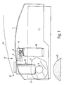
- the basic lens edging machine comprises a chuck 1 for a lens 2, the chuck being arranged to hold the lens centrally so as to free the edge of the lens for grinding.
- the chuck 1 is provided in housing 3 below which a further housing (not shown) accommodates a pair of grinding wheel 4 and 5 representing first and second grinding means.
- the housing 3 accommodates further grinding apparatus generally indicated at 6 and representing third grinding means.
- the housing 3 has a cover 7 part of which 8 is hinged at 9 for upward movement to a generally vertical position.
- An overall cover 11 is hinged at 12, again for movement to a generally vertical position.
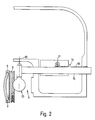
- the grinding apparatus 6 is constructed in accordance with the present invention and comprises a grinding wheel 13 which is moved between operative and inoperative positions by a rack and pinion mechanism 14.
- the rack 15 of the rack and pinion mechanism 14 is mounted generally horizontally and has a toothed section 16 which is engaged by the pinion 17 driven by an electric motor 18.
- the grinding wheel 13 is mounted on one end of the rack 15 and is mounted for pivotal movement in a generally vertical plane about a generally horizontal pivot axis 19.
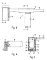
- the grinding wheel 13 is in the form of a sleeve 21 impregnated or surfaced with a grinding medium 22 such as diamond dust.
- the sleeve 21 is closed at one end 23 and open at the opposite end through which it is placed over the body 24 of an electric motor 25 having an output shaft 26.
- the motor may be a standard, readily available motor.
- the sleeve 21 is mounted for rotation on the motor body 24 by two spaced ball or roller bearings 27 which are separated by a spacer 28.
- the output shaft 26 is attached to the sleeve 21 via an element 29 fitted into the closed end of the sleeve for rotation therewith.
- the motor 25 is mounted in a housing 31 fitted with a sleeve 32 through which electric leads for the motor are taken and which provides the pivot axis 19 for the grinding apparatus 6. It will be seen that when the motor is energised, the output shaft 26 rotates and hence drives with it the sleeve 21.
- the grinding apparatus 6 is extremely compact and a motor 17mm in diameter has been successfully used which gives an overall grinding wheel 13 diameter of 31mm, and length of 56mm.
- a lens 2 is loaded into the chuck 1 through the lids or covers 7,11 which are then closed.
- the lens 2 is then automatically ground to the required shape and size by the relative course grinding wheel 4 which follows a physical or electronically memorised replica of the required shape (not shown).
- the grinding wheel 5 is then automatically brought to the lens 2 and a peripheral ridge ground thereon.
- the lens 2 is now finished except for the provision of a safety bevel at least in the edge of the lens in use facing the wearer.
- the motors 18 and 25 are energised, the former driving the pinion 17 relative to the rack 15, whereby the grinding apparatus 6 is moved from its inoperative position of Figure 2 to the operative position in which it contacts the edge of the lens 2, the rack still being driven after initial contact between lens and grinding wheel 13 which the latter pivots about axis 19.
- the safety bevel is immediately ground with the contact pressure between the sleeve 21 and the lens 2 being essentially only due to pivoting.
- the safety bevel grinding operation typically lasts for a few seconds as only a fraction of a millimetre has to be ground off the lens.
- the grinding wheel 13 is retracted to its inoperative position by reversing the motor 18 and the latter, together with the motor 25, de-energised when the grinding wheel is in the inoperative position.
- All sizes of lenses can be accommodated without any adjustment of the height of the grinding apparatus 6 because the slightly different angle of the bevel as between one size of lens and another which will result in immaterial as only a fraction of a millimetre (1 ⁇ 4-1 ⁇ 2 mm) of material is removed during the grinding of the safety bevel.
Landscapes
- Engineering & Computer Science (AREA)
- Mechanical Engineering (AREA)
- Chemical & Material Sciences (AREA)
- Ceramic Engineering (AREA)
- Inorganic Chemistry (AREA)
- Grinding And Polishing Of Tertiary Curved Surfaces And Surfaces With Complex Shapes (AREA)
Applications Claiming Priority (2)
| Application Number | Priority Date | Filing Date | Title |
|---|---|---|---|
| GB9220345 | 1992-09-25 | ||
| GB9220345A GB2270865A (en) | 1992-09-25 | 1992-09-25 | Grinding apparatus |
Publications (1)
| Publication Number | Publication Date |
|---|---|
| EP0589628A1 true EP0589628A1 (de) | 1994-03-30 |
Family
ID=10722552
Family Applications (1)
| Application Number | Title | Priority Date | Filing Date |
|---|---|---|---|
| EP93307342A Withdrawn EP0589628A1 (de) | 1992-09-25 | 1993-09-16 | Schleifvorrichtung |
Country Status (3)
| Country | Link |
|---|---|
| EP (1) | EP0589628A1 (de) |
| CA (1) | CA2106505A1 (de) |
| GB (1) | GB2270865A (de) |
Cited By (2)
| Publication number | Priority date | Publication date | Assignee | Title |
|---|---|---|---|---|
| FR2751256A1 (fr) * | 1996-07-22 | 1998-01-23 | Briot Int | Machine de meulage de verres optiques |
| FR2751255A1 (fr) * | 1996-07-22 | 1998-01-23 | Briot Int | Machine de meulage de verres optiques |
Citations (6)
| Publication number | Priority date | Publication date | Assignee | Title |
|---|---|---|---|---|
| AT178560B (de) * | 1952-03-21 | 1954-05-25 | Franz Ing Neumueller | Transportable Schleifmaschine |
| DE2931822A1 (de) * | 1979-08-06 | 1981-02-26 | Festo Maschf Stoll G | Schleif- oder poliergeraet |
| EP0098950A2 (de) * | 1982-06-12 | 1984-01-25 | Wernicke & Co. GmbH | Brillenglasrandschleifmaschine, insbesondere Handschleifmaschine |
| DE8708313U1 (de) * | 1987-06-12 | 1987-08-06 | Wernicke & Co GmbH, 4000 Düsseldorf | Brillenglasrandschleifmaschine mit einem Antriebsmotor für mehrere Schleifscheiben |
| DE3831860A1 (de) * | 1987-12-28 | 1989-07-06 | Werkzeugmasch Okt Veb | Anordnung zur drehmomentabhaengigen regelung der druckluftzufuhr bei druckluftwerkzeugmaschinen |
| US5056270A (en) * | 1988-07-07 | 1991-10-15 | Berkshire Ophthalmic Laboratories Limited | Method and apparatus for grinding lenses |
Family Cites Families (2)
| Publication number | Priority date | Publication date | Assignee | Title |
|---|---|---|---|---|
| GB231434A (en) * | 1924-03-27 | 1926-04-29 | Reynier Sa Ets | New or improved electrical driving mechanism for rotary tools for use in the treatment of leather and hides or skins |
| CH556212A (de) * | 1972-02-07 | 1974-11-29 | Mo Stankostroitelny Z Shilfova | Werkzeugkopf. |
-
1992
- 1992-09-25 GB GB9220345A patent/GB2270865A/en not_active Withdrawn
-
1993
- 1993-09-16 EP EP93307342A patent/EP0589628A1/de not_active Withdrawn
- 1993-09-20 CA CA 2106505 patent/CA2106505A1/en not_active Abandoned
Patent Citations (6)
| Publication number | Priority date | Publication date | Assignee | Title |
|---|---|---|---|---|
| AT178560B (de) * | 1952-03-21 | 1954-05-25 | Franz Ing Neumueller | Transportable Schleifmaschine |
| DE2931822A1 (de) * | 1979-08-06 | 1981-02-26 | Festo Maschf Stoll G | Schleif- oder poliergeraet |
| EP0098950A2 (de) * | 1982-06-12 | 1984-01-25 | Wernicke & Co. GmbH | Brillenglasrandschleifmaschine, insbesondere Handschleifmaschine |
| DE8708313U1 (de) * | 1987-06-12 | 1987-08-06 | Wernicke & Co GmbH, 4000 Düsseldorf | Brillenglasrandschleifmaschine mit einem Antriebsmotor für mehrere Schleifscheiben |
| DE3831860A1 (de) * | 1987-12-28 | 1989-07-06 | Werkzeugmasch Okt Veb | Anordnung zur drehmomentabhaengigen regelung der druckluftzufuhr bei druckluftwerkzeugmaschinen |
| US5056270A (en) * | 1988-07-07 | 1991-10-15 | Berkshire Ophthalmic Laboratories Limited | Method and apparatus for grinding lenses |
Cited By (4)
| Publication number | Priority date | Publication date | Assignee | Title |
|---|---|---|---|---|
| FR2751256A1 (fr) * | 1996-07-22 | 1998-01-23 | Briot Int | Machine de meulage de verres optiques |
| FR2751255A1 (fr) * | 1996-07-22 | 1998-01-23 | Briot Int | Machine de meulage de verres optiques |
| EP0820837A1 (de) * | 1996-07-22 | 1998-01-28 | Briot International | Maschine zum Schleifen optischer Gläser |
| US5882247A (en) * | 1996-07-22 | 1999-03-16 | Briot International | Machine for grinding of optical glasses |
Also Published As
| Publication number | Publication date |
|---|---|
| CA2106505A1 (en) | 1994-03-26 |
| GB2270865A (en) | 1994-03-30 |
| GB9220345D0 (en) | 1992-11-11 |
Similar Documents
| Publication | Publication Date | Title |
|---|---|---|
| JP3883773B2 (ja) | レンズ周縁研削装置 | |
| US5056270A (en) | Method and apparatus for grinding lenses | |
| US5053971A (en) | Method and apparatus for edging an optical lens | |
| US6719609B2 (en) | Eyeglass lens processing apparatus | |
| US7137871B2 (en) | Spectacle lens edging machine | |
| EP1138436B1 (de) | Linsenrand-Schleifmaschine | |
| US6168505B1 (en) | Polishing machine for spectacle lenses | |
| EP0820837B1 (de) | Maschine zum Schleifen optischer Gläser | |
| EP1034884A2 (de) | Vorrichtung zum Darstellen der Kegelform einer Brillenglaslinse und Verfahren und Vorrichtung zum Bearbeiten des Linzenrandes unter Anwendung dieser Darstellungsvorrichtung | |
| GB2270865A (en) | Grinding apparatus | |
| JPS58177256A (ja) | レンズ周縁加工機 | |
| EP1352707B1 (de) | Vorrichtung zur Bearbeitung eines Brillenglases | |
| US5454748A (en) | Process, block for sucker or a machine for grinding or machining the edge of eyeglass lenses and a process for grinding eyeglass lenses | |
| EP1738868B1 (de) | Brillenglasbearbeitungsmaschine | |
| US5408792A (en) | Process, block or sucker for a machine for grinding or machining the edge of eyeglass lenses and a process for grinding eyeglass lenses | |
| KR100591473B1 (ko) | 안경 렌즈 가공 장치 및 방법 | |
| US4373298A (en) | Automatic edge beveller for removing the sharp peripheral edges of ophthalmic lenses | |
| JP2868516B2 (ja) | 光コネクタフェルール端面加工装置、及び方法 | |
| JP4326507B2 (ja) | レンズ周縁加工装置 | |
| JPH07186025A (ja) | レンズ面取装置 | |
| JPH0632891B2 (ja) | 玉摺機 | |
| JPH0239727Y2 (de) | ||
| GB2117287A (en) | Lens edge grinding machine | |
| JPH10249694A (ja) | レンズ周縁加工装置 | |
| JPH06155264A (ja) | レンズ形状測定装置及びこれを有するレンズ研削装置 |
Legal Events
| Date | Code | Title | Description |
|---|---|---|---|
| PUAI | Public reference made under article 153(3) epc to a published international application that has entered the european phase |
Free format text: ORIGINAL CODE: 0009012 |
|
| AK | Designated contracting states |
Kind code of ref document: A1 Designated state(s): AT BE DE ES FR GB IT NL SE |
|
| 17P | Request for examination filed |
Effective date: 19940929 |
|
| STAA | Information on the status of an ep patent application or granted ep patent |
Free format text: STATUS: THE APPLICATION IS DEEMED TO BE WITHDRAWN |
|
| 18D | Application deemed to be withdrawn |
Effective date: 19960402 |