EP0589633A2 - Conducteur de stimulateur cardiaque - Google Patents
Conducteur de stimulateur cardiaque Download PDFInfo
- Publication number
- EP0589633A2 EP0589633A2 EP93307357A EP93307357A EP0589633A2 EP 0589633 A2 EP0589633 A2 EP 0589633A2 EP 93307357 A EP93307357 A EP 93307357A EP 93307357 A EP93307357 A EP 93307357A EP 0589633 A2 EP0589633 A2 EP 0589633A2
- Authority
- EP
- European Patent Office
- Prior art keywords
- wire
- needle
- cardiac pacing
- pacing
- lead
- Prior art date
- Legal status (The legal status is an assumption and is not a legal conclusion. Google has not performed a legal analysis and makes no representation as to the accuracy of the status listed.)
- Granted
Links
Images



Classifications
-
- A—HUMAN NECESSITIES
- A61—MEDICAL OR VETERINARY SCIENCE; HYGIENE
- A61N—ELECTROTHERAPY; MAGNETOTHERAPY; RADIATION THERAPY; ULTRASOUND THERAPY
- A61N1/00—Electrotherapy; Circuits therefor
- A61N1/02—Details
- A61N1/04—Electrodes
- A61N1/05—Electrodes for implantation or insertion into the body, e.g. heart electrode
- A61N1/0587—Epicardial electrode systems; Endocardial electrodes piercing the pericardium
-
- A—HUMAN NECESSITIES
- A61—MEDICAL OR VETERINARY SCIENCE; HYGIENE
- A61N—ELECTROTHERAPY; MAGNETOTHERAPY; RADIATION THERAPY; ULTRASOUND THERAPY
- A61N1/00—Electrotherapy; Circuits therefor
- A61N1/02—Details
- A61N1/04—Electrodes
- A61N1/05—Electrodes for implantation or insertion into the body, e.g. heart electrode
-
- A—HUMAN NECESSITIES
- A61—MEDICAL OR VETERINARY SCIENCE; HYGIENE
- A61N—ELECTROTHERAPY; MAGNETOTHERAPY; RADIATION THERAPY; ULTRASOUND THERAPY
- A61N1/00—Electrotherapy; Circuits therefor
- A61N1/02—Details
- A61N1/04—Electrodes
- A61N1/05—Electrodes for implantation or insertion into the body, e.g. heart electrode
- A61N1/056—Transvascular endocardial electrode systems
- A61N1/057—Anchoring means; Means for fixing the head inside the heart
- A61N1/0573—Anchoring means; Means for fixing the head inside the heart chacterised by means penetrating the heart tissue, e.g. helix needle or hook
-
- A—HUMAN NECESSITIES
- A61—MEDICAL OR VETERINARY SCIENCE; HYGIENE
- A61N—ELECTROTHERAPY; MAGNETOTHERAPY; RADIATION THERAPY; ULTRASOUND THERAPY
- A61N1/00—Electrotherapy; Circuits therefor
- A61N1/02—Details
- A61N1/04—Electrodes
- A61N1/05—Electrodes for implantation or insertion into the body, e.g. heart electrode
- A61N1/0587—Epicardial electrode systems; Endocardial electrodes piercing the pericardium
- A61N1/059—Anchoring means
-
- A—HUMAN NECESSITIES
- A61—MEDICAL OR VETERINARY SCIENCE; HYGIENE
- A61N—ELECTROTHERAPY; MAGNETOTHERAPY; RADIATION THERAPY; ULTRASOUND THERAPY
- A61N1/00—Electrotherapy; Circuits therefor
- A61N1/02—Details
- A61N1/04—Electrodes
- A61N1/05—Electrodes for implantation or insertion into the body, e.g. heart electrode
- A61N1/0587—Epicardial electrode systems; Endocardial electrodes piercing the pericardium
- A61N1/0592—Introducing the lead through the pericardium with a needle
-
- A—HUMAN NECESSITIES
- A61—MEDICAL OR VETERINARY SCIENCE; HYGIENE
- A61N—ELECTROTHERAPY; MAGNETOTHERAPY; RADIATION THERAPY; ULTRASOUND THERAPY
- A61N1/00—Electrotherapy; Circuits therefor
- A61N1/02—Details
- A61N1/04—Electrodes
- A61N1/05—Electrodes for implantation or insertion into the body, e.g. heart electrode
- A61N1/0587—Epicardial electrode systems; Endocardial electrodes piercing the pericardium
- A61N1/0595—Temporary leads
Definitions
- the field of art to which this invention relates is surgical electrode leads, more particularly, cardiac pacing and monitoring leads.
- Conventional temporary pacing leads typically consist of a conductive wire lead and a surgical needle for implantation in the myocardium.
- the needle typically has a distal piercing end and a proximal end which is attached to the distal end of the wire lead.
- An electrode needle is typically attached to the proximal end of the wire lead.
- the wire lead typically has an insulated section and a distal conductive section where the insulation has been removed. The distal conductive section is implanted in the cardiac muscle.
- the electrode needle is typically pushed through the thoracic cavity wall ( i.e., from the interior to the exterior) and the insulated section of the wire lead is partially pulled through.
- the electrode needle is connected to conventional pacing and monitoring equipment.
- Conventional wire leads are typically made from multi-filament conducting materials such as stainless steel.
- the leads are insulated with bio-compatible polymer coatings . It is important that the wire have a feel to the surgeon similar to that of a conventional suture. This is known in this art as "hand".
- Conventional cardiac pacing leads are typically used in the following manner. Initially, the surgeon inserts the curved surgical needle into the myocardium. Next, the surgeon pushes the needle through and out of the myocardium such that a portion of the uninsulated, distal conductive section of the pacing wire is implanted in a needle pathway formed in the myocardium by the surgical needle. The surgical needle is then cut from the pacing wire, and, the pacing wire is optionally anchored to the heart with a suture.
- the surgeon pushes the scored electrode needle, connected to the proximal end of the pacing wire, out through the wall of the thoracic cavity so that the electrode needle and a length of the insulated section of electrode lead wire are positioned external to the chest of the patient.
- the electrode needle is then broken at the score line and inserted into the appropriate receptacle of a conventional electronic pacing and monitoring device.
- the leads are removed from the patient, after the patient has been stabilized, in the following manner.
- the surgeon disconnects the electrode needle from the monitoring/pacing device.
- the surgeon grasps the external faction of the pacing wire and pulls it by applying traction( i.e., an axial, rearward force), thereby pulling the lead from the myocardium and out through the chest wall.
- pacing leads must have certain characteristics. First of all, the lead wire must be very flexible and resistant to fatigue failure resulting from repeated flexing cycles. It can be appreciated that a cardiac patient may have the pacing leads in place for periods of time up to and exceeding two or three weeks. During that time normal voluntary and involuntary movements by the patient(such as heartbeats, respiration and am- bulation) will result in repetitive flexing of the wire lead. Another requirement for cardiac pacing leads is that the implanted myocardial lead must remain in place when subjected to typical stress and strain caused by typical patient movement and activities.
- the implanted lead must be easily withdrawn from the myocardium by the application of an axial force, i.e., traction, to the wire lead.
- the pacing wire be constructed of material having a low electrical resistance.
- the cardiac pacing leads should be easy to manufacture.
- the cardiac leads must be sufficiently flexible to provide the surgeon with a "hand" similar to that of a conventional suture.
- Still another requirement of a pacing lead is biocompatability such that the pacing lead is corrosion resistant, nontoxic, and non-allergenic.
- Conventional cardiac pacing leads are known to have deficiencies.
- conventional pacing leads use a multi-conductor(filament) wire having an outer electrically insulating coating such as the multi-filament stainless steel sutures disclosed in U.S. Patent No. 3,125,095.
- Amulti-filament pacing wire although providing the required "hand", flexibility and resistance to fatigue, also allows the growth of tissue into the interstices of the wire in sections where the outer insulation has been removed. This tissue ingrowth complicates and may impeded removal of the pacing lead from the heart.
- multi- filament wire is difficult to work with. For example, it is difficult to strip all of the insulation coating from a multi- filament wire using conventional wire stripping equipment.
- a residue of insulation in the interstices between the filaments is typically left behind. Any residual insulation may adversely affect pacing and monitoring.
- the use of a single filament wire would eliminate some of these disadvantages.
- single filament wires made from conventional metals may have been used for cardiac pacing leads, they have the disadvantages of not having the proper "hand" and of being susceptible to fatigue fracture or failure.
- Another disadvantage of conventional pacing leads is that the pacing lead must somehow be anchored in the myocardium. This is frequently done by suturing the electrical lead in place to the heart muscle using conventional suture materials. The additional sutures required for anchoring may increase the trauma to the heart and may complicate removal of the pacing lead.
- Another method of anchoring is the use of helical suture structures affixed distally to the pacing lead.
- U.S. Patent No. 4,341,226 discloses a temporary lead for cardiac pacing or monitoring purposes. The lead has a curved needle having an attached surgical suture with a proximal helix molded into the suture immediately distal to the pacing lead.
- the helical suture and pacing lead are placed within the myocardium and the helical suture serves to anchor the lead within the myocardium.
- the helical anchor suture is typically nonconductive and this type of cardiac pacing lead typically has less conductive surface in contact with the myocardium.
- Yet another method of anchoring a pacing wire involves inserting a pacing wire which is completely insulated into the myocardium. An excess length is pulled through the myocardium. The surgeon the strips the insulation off from opposite sides of a section of the wire forming two small wings of stripped insulation material. The surgeon then applies traction on the lead, thereby pulling the excess lead back into the myocardium until the stripped section of wire is in the myocardium.
- the wings of insulation remain exterior to the myocardium and serve as an anchor.
- the stripping is typically done with a scalpel blade.
- This method of anchoring has many disadvantages including the additional time necessary to perform the wire stripping procedure as well as danger to the patient and surgeon while attempting to strip insulation from a wire lead with a scalpel.
- pacing leads such as those disclosed in U.S. Patent No. 4,341,226 have a conductive section which is larger in diameter than the pathway formed by the surgical needle in the myocardium. This results in additional stress or trauma to the myocardium when the conductive section is inserted or removed.
- a pacing lead having a single conductor wire which has the flexibility of a multi-conductor wire pacing lead.
- the pacing lead comprises a conductive wire comprising a biocompatible, low modulus metal.
- the wire has a proximal end and a distal end.
- the wire comprises a single filament conductor.
- Asurgical needle is conductively attached to the distal end of said wire for insertion into and through heart muscle.
- An electrode needle is conductively attached to the proximal end of the wire for connection to an external pacing or monitoring device.
- An integral anchor is formed into the distal end of the wire for anchoring the lead in the myocardium.
- the wire comprises a single filament conductor.
- the wire has a proximal end and a distal end.
- the wire comprises a single filament conductor.
- a surgical needle may be conductively attached to the distal end of said wire for insertion into and through heart muscle.
- An electrode needle may be conductively attached to the proximal end of the wire for connection to an external pacing or monitoring device.
- An integral anchor is formed into the distal end of the wire for anchoring the lead in the myocardium of a mammal.
- Another aspect of the present invention is a method of cardiac pacing or monitoring using the previously- described cardiac pacing lead.
- the method comprises inserting the surgical needle and the distal end of the conductive wire, including the anchor means, into the myocardial heart muscle of a mammal. Then, inserting the electrode needle through the chest wall of the mammal along with the proximal end of the conductive wire means and inserting the electrode means into a cardiac pacing and/or monitoring device. And, then pacing and/or monitoring the heart of the mammal.
- the cardiac pacing lead 10 of the present invention is illustrated in FIGS. 1-5 and FIGS. 7A-F.
- the cardiac pacing lead 10 is seen to have a single filament, electrically conductive, low modulus wire 20 having proximal end 22 and distal end 24.
- the wire 20 also has distal tip 25 and proximal tip 23.
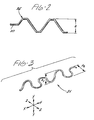
- the conductive, low modulus wire 20 is seen to have electrically insulating coating 26. A portion of the insulating coating 26 is seen to be removed from a distal section 30 of the conductive wire 20. At least part of section 30 of the conductive wire 20 will be in electrical contact with the myocardium for transmitting and receiving electrical signals. Formed into section 30 is the integral anchor means 35.
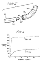
- Surgical needle 40 is seen to have distal point 42 and proximal mounting cavity 44( as seen in FIG.5 ) for mounting the distal tip 25 of the conductive wire 20.
- the distal tip 25 of conductive wire 20 is inserted into the mounting cavity 44 of needle 40 and mounted in a conventional manner such as swaging, welding, brazing, bonding with a medically approved bonding agent such as epoxy( e.g., a conductive epoxy) and shrink fitting and the like.
- a medically approved bonding agent such as epoxy( e.g., a conductive epoxy) and shrink fitting and the like.
- the distal tip 25 may be of a lesser diameter than the wire 20 to facilitate mounting in cavity 44. It is desirable, although not necessary, that the connection between tip 25 and the needle 40 in cavity 44 be sufficient to provide effective electrical conduction between the wire 20 and the needle 40.
- the needle 40 is typically a conventional curved myocardial surgical needle having a conventional distal piercing point and a conventional proximal end 43 with a cavity 44 suitable for receiving a suture or a wire.
- the diameter of the wire 20 will be less than or equal to the maximum trans-axial dimension (e.g., diameter) of the needle 40.
- the needle 40 is preferably made from a conductive metal conventionally used to manufacture surgical needles such as martensitic stainless steel, maraging stainless steel, plated carbon steel, cold drawn austenitic stainless steel and the like. However, if one were willing to accept any disadvantages which may be attendant, if any, the needle 40 could be made of non-metallic conducting materials having the requisite mechanical characteristics for use as a surgical needle.
- the electrode needle 60 is attached to the proximal tip 23 of the conductive wire 20.
- the needle 60 is typically a conventional electrode needle and has a straight configuration having a proximal point 62 and a distal end 64 containing mounting cavity 65.
- the electrode needle 60 has scoreline 68 centrally located about the circumference of the needle. The scoreline 68 will be of sufficient depth so that the proximal end 63 of the needle 60 may be easily broken off leaving an electrode portion 70 for insertion into an electronic cardiac pacing/monitoring instrument 80.
- Distal end 64 of the needle 60 has mounting cavity 65 for receiving proximal tip 23 of wire 20. The tip 23 must be mounted such that it is in sufficient mechanical engagement with needle 60 in cavity 65 to provide effective electrical contact.
- the needle 60 will be made from conventional materials such as marten-sitic stainless steel, maraging stainless steel, plated carbon steel, cold drawn austenitic stainless steel and the like having sufficient conductivity to effectively transmit low level electrical signals. Electrode needles are disclosed in United States Patent No. 4,010,756 which is incorporated by reference.
- the conductive wire 20 will be made from a single filament, low modulus metal having the requisite electrical properties, biocompatibility properties and mechanical properties.
- low modulus as used herein is defined to mean a modulus of elasticity in tension of less than 2.0 X 10 6 pounds per square inch( psi).
- metal is defined to include metal alloys.
- the metals useful to form the conductive wires 20 of the present invention will typically have the following characteristics : "hand”, low modulus of elasticity, good fatigue resistance and biocompatiblity including corrosion resistance.
- low modulus metals which can be used include the various shape memory alloys such as Nitinol, gold-cadmium alloys, titanium-niobium alloys, nickel-titanium-copper alloys, nickel-titanium-platinum alloys and nickel-titanium-palladium alloys.
- the alloys will typically have the following compositions: Nickel-titanium with 50 % nickel or less, Nickel-titanium-copper alloys with about 5 to about 20 % copper, Nickel-titanium-platinum alloys with above about 15 % platinum, and nickel-platinum-palladium alloys with above about 18% palladium. It is preferred to use the nickel-titanium alloys which are often referred to as shape memory effect alloys.
- the low modulus, single filament, conductive wire 20 will have an electrical conductivity sufficient to prevent attenuation of cardiac pacing signals or myocardial electrical activity signals.
- the electrical resistivity of the material will typically be about 50 to about 200 microhm-cm, more typically about 60 to about 120 microhm-cm, and preferably about 80 to about 100 microhm-cm.
- the conductive wire 20 will have sufficient mechanical strength and resistance to fatigue to effectively prevent fatigue failure or tensile failure of the wire 20 while implanted in a cardiac patient.
- the wire 20 will have sufficient yield strength to prevent the anchor means 35 from straightening out in the tissue pathway created in the myocardium by the surgical needle 40.
- thewire20 will have a yield strength of less than about40,000 pounds per square inch, more typically less than about 30,000 pounds per square inch, and preferably less than about 20,000 pounds per square inch.
- the wire 20 will typically have a U.S.P. size of 1/0, 2/0 or 3/0 as indicated in the U.S. Pharmacopeia which is incorporated by reference.
- the wire 20 has an electrically insulative, polymer coating 26 sufficient to effectively prevent conduction through the coating.
- the coating 26 will have a thickness of about 2.0 mils to about 50.0 mils, more typically about 2.0 mils to about 25.0 mils, and preferably about 3.0 mils to about 8.0 mils.
- the coating 26 will contain conventional biocompatible polymers and copolymers including polyethylene, polypropylene, Teflon@ (polytetrafluoroethylene), fluorinated ethylenepolypropylene, and equivalents thereof.
- the insulative coating 26 will be applied in conventional manners such as spraying, rolling, brushing,extruding and the like. It is also possible to use a shrink-type tube of insulation material applied concentrically about the wire and actuated by application of sufficient energy to shrink and engage the wire 20 to form coating 26.
- the anchor section 35 of the pacing lead 10 is typically formed in the following manner.
- a section of the insulation coating 26 is removed from a distal section of wire 20, using a conventional wire stripping apparatus, to produce the uninsulated section 30.
- the section 30 of the wire 20 is fed into a conventional press apparatus having dies, and, is compressed in the apparatus using sufficient force to permanently deform the section 30 into a desired anchor configuration or wave form.
- the anchor 35( as seen in FIG. 2 ) is made by rolling or pressing section 30 between two rotatably mounted, meshing gears. Any conventional process may be used to form anchor 35 including mechanical processes such as that described above, wherein the form or configuration of the anchor 35 is set into the section 30.
- FIGS. 7A-7F Several configurations for the anchor 35 are illustrated in FIGS. 7A-7F.
- the configurations which can be used for anchor 35 include any configurations effective to produce sufficient anchoring of the pacing lead 10 in the myocardium without disengaging from the needle pathway in response to typical patient movements.
- the shapes include any conventional waveform including sinusoidal, square, saw tooth, and gear, either full wave or half wave or combinations thereof, for example, as seen in FIGS. 7A-F.
- the waves will typically repeat with a desired periodicity and will have a sufficient amplitude to provide effective anchoring in the myocardium.
- the anchors may have two-dimensional or three-dimensional configurations (as shown in FIG. 3) wherein the waveforms or shapes are rotated periodically about the longitudinal axis of the wire.
- the anchor 35 may have a variety of different shapes which are effective to anchor the wire 20 in the myocardium, including a helix.
- the force to remove the anchor 35 from a needle pathway in heart muscle will vary with the size and configuration of the anchor as well as the length and size of the needle pathway.
- the force will typically be about 17 grams to about 1000 grams, more typically about 100 grams to about 300 grams, and preferably about 150 grams to about 300 grams.
- a typical amplitude "A" for the anchor 35 is seen in FIG. 2.
- the amplitude A is defined to be the sum of the maximum distance above and below the longitudinal center line of the wire 20.
- the amplitude A of anchor 35 is sufficient to effectively anchor the pacing lead 10 in the myocardium.
- amplitude A is about 15 mils to about 75 mils, more typically about 20 mils to about 60 mils, and preferably about 25 mils to about 50 mils.
- the frequency will be sufficient to provide effective retention in the heart muscle.
- the frequency will be about 1 cycle per inch to about 20 cycles per inch, more typically about 5 cycles per inch to about 15 cycles per inch, and preferably about 5 cycles per inch to about 10 cycles per inch.
- the length of the anchor 35 will vary depending upon such variables including the type of patient and the desired withdrawal force.
- the length of anchor 35 will be sufficient to effectively prevent inadvertent withdrawal from the cardiac muscle by providing effective retention in a needle pathway in cardiac muscle.
- the length of the anchor 35 will be about 0.5 inches to about 3.0 inches, more typically about 0.75 inches to about 2.0 inches, and preferably about 1.0 inches to about 1.5 inches.
- the cardiac pacing lead 20 In order to have the proper hand, the cardiac pacing lead 20 must have a wire section 20 which has a feel or stiffness (i.e., "hand") similar to a conventional surgical suture.
- Conventional surgical sutures are typically made from materials such as polypropylene, dacronpolyester and absorbable polymeric materials.
- the modulus of elasticity of the conventional suture materials ranges from about 100,000 psi to about 2,000,000 psi. Therefore, the modulus of elasticity of the metals suitable to make the wire 20 will be sufficient to effectively provide a hand comparable to conventional sutures.
- the modulus of elasticity will be about 1 X 10 6 psi to about 2 X 10 6 psi, more typically about 1.2 X 10 6 psi to about 1.8 X 10 6 psi, and preferably about 1.4 X 10 6 psi to about 1.6 X 10 6 psi.
- a diagram of stress versus percent strain is illustrated in FIG. 6 showing curves for Type 316-L stainless steel and Nitinol, respectively. Nitinol, which has a "hand” similar to conventional sutures, is seen to undergo percentage increases in strain at significantly lower stress values than- stainless steel. This behavior is characteristic of low modulus materials having the desired "hand".
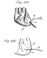
- the cardiac pacing leads 10 of the present invention are typically used in the following manner, as illustrated in FIGS. 4A-4C.
- the needle 40 of the pacing lead 10 is inserted into and through the pericardium of the patient's atria or ventricles and the needle is pushed through until the tip 42 is exposed (thereby creating a needle pathway in the heart muscle).
- the surgeon grasps the tip 42 with a surgical grasping instrument and pulls the needle through the heart muscle until the anchor section 35 of the conductive wire 20 is sufficiently in place in the heart muscle to effectively anchor the pacing lead 10.
- the needle 40 is cut from the distal end 24 of the wire 20.
- the surgeon pushes the electrode needle 60 outward from the interior of the thoracic cavity through the intercostal spaces in the patient's thoracic cavity wall until the distal end 63 of the needle 60 protrudes through the exterior of the thoracic cavity wall.
- the surgeon grasps the end 63 of the needle with a conventional needle grasper or holder and pulls the needle 60 and an insulated, proximal of the wire 20 through the thoracic cavity wall.
- the surgeon breaks the end 63 off of the needle 60 by grasping the proximal end 63 and the distal end 64 of the needle 60 and applying a bending moment about the score line 68.
- the physician inserts the electrode portion 70 of the needle 60 into a receptacle on a cardiac pacing/monitoring instrument 80.
- the cardiac pacing lead 10 then serves as an electrical connection between the patient's pericardium and the cardiac pacing/monitoring instrument 80.
- the patient's heart is monitored or paced by the cardiac pacing/monitoring instrument 80 through the cardiac pacing lead 10.
- the pacing lead 10 is removed by initially disconnecting the electrode section 70 of the electrode needle 60 from the cardiac pacing/monitoring equipment. Then, the surgeon applies traction by applying an axial proximal force on the cardiac pacing lead 10 and removes the anchor 32 and the wire 20 by pulling the assembly out through the patient's chest wall.
- Nitinol wire 20 having a diameter of 15 mil was used to manufacture cardiac pacing leads 10.
- the composition of the Nitinol was 49.5% Ni and 50.5% Ti.
- a distal section 30 of insulation 26 was removed using conventional wire stripping equipment.
- An anchor 35 was formed in the wire 20 by running the distal section 30 of the wire 20 through a set of rotating gears. The anchor 35 had a wave form configuration as seen in FIG.2.
- a conventional surgical needle 40 was swaged to the distal tip 25 of the wire 20.
- the leads 10 were implanted into a porcine heart using two conventional techniques used in cardiac surgery. Using the first technique, the leads 10 were passed through the pericardium and anchor 35 was implanted into the myocardium of the right ventricle. Using the second technique, the anchors 35 of leads 10 were implanted into the myocardium of the left ventricle after the pericardium was excised.
- the implanted leads 10 were removed by clamping the proximal ends 22 in an lnstron® tensile tester and applying a steady upward force. The removal force as a function of time was recorded. The peak removal force was used for comparison. Test results are listed in the Table.
- the peak removal force of the pacing leads 10 of the present invention varies as a function of the amplitude and frequency of the anchor shape. Typical anchor shapes are illustrated in FIGS. 7A-7F. In this example, the anchors with the higher frequency had higher peak removal force values for a given amplitude. As amplitude increased, the force to remove also increased. The amplitude and frequency of the anchors for each test run is listed in the Table.
- a mammal is prepared for cardiac surgery using conventional surgical preparatory techniques.
- the surgeon then enters the patient's chest cavity by cutting through the sternum and expanding the rib cage with a chest expander.
- a conventional cardiac bypass surgical procedure is then performed.
- the surgeon implants a cardiac pacing lead 10 by inserting the needle 40 through the pericardium into the myocardium of the left ventricle.
- the needle 40 is pulled with a conventional needle holder through the myocardium until the anchor 35 is set in place in the pathway formed by needle 40.
- the needle 40 is then cut off from the distal end 24 of wire 20 and removed from the thoracic cavity.
- the patient's heart is monitored and paced by the instrument 80 through the cardiac pacing lead 10.
- the wire 20 has a hand similar to conventional sutures.
- the pacing lead 10 remains in the patient during a recuperation period.
- the anchor 35 effectively holds the conductive section 30 in the myocardium. Tissue ingrowth is minimized.
- the pacing lead 10 is removed by disconnecting the electrode 70 from the pacing/monitoring instrument 80 and the proximal end of the wire 20 is grasped and pulled outwardly by the surgeon such that the wire 40 and the anchor 35 are withdrawn from the cardiac muscle and out through the chest wall of the patient. Removal of the pacing lead 10 is facilitated by minimal tissue ingrowth.
- the cardiac pacing leads 10 of the present invention have many advantages.
- the low modulus wire 20 is a single filament but has the "hand" of a conventional multi-filament wire without the disadvantages attendant with a multi-filament wire.
- the lead 10 is easier to manufacture than multifilament pacing leads but yet has the required electrical and mechanical properties.
- the integral anchor 35 formed into the lead 10 provides anchoring without the need for either suturing or additional anchor elements.
- the lead 10 having a single filament wire 20 minimizes or eliminates tissue infiltration associated with multi-filament pacing leads.
Landscapes
- Health & Medical Sciences (AREA)
- Heart & Thoracic Surgery (AREA)
- Cardiology (AREA)
- Animal Behavior & Ethology (AREA)
- Engineering & Computer Science (AREA)
- Biomedical Technology (AREA)
- Nuclear Medicine, Radiotherapy & Molecular Imaging (AREA)
- Radiology & Medical Imaging (AREA)
- Life Sciences & Earth Sciences (AREA)
- General Health & Medical Sciences (AREA)
- Public Health (AREA)
- Veterinary Medicine (AREA)
- Vascular Medicine (AREA)
- Electrotherapy Devices (AREA)
Applications Claiming Priority (2)
| Application Number | Priority Date | Filing Date | Title |
|---|---|---|---|
| US947207 | 1992-09-18 | ||
| US07/947,207 US5350419A (en) | 1992-09-18 | 1992-09-18 | Cardiac pacing lead |
Publications (3)
| Publication Number | Publication Date |
|---|---|
| EP0589633A2 true EP0589633A2 (fr) | 1994-03-30 |
| EP0589633A3 EP0589633A3 (en) | 1995-12-27 |
| EP0589633B1 EP0589633B1 (fr) | 2000-01-26 |
Family
ID=25485732
Family Applications (1)
| Application Number | Title | Priority Date | Filing Date |
|---|---|---|---|
| EP93307357A Expired - Lifetime EP0589633B1 (fr) | 1992-09-18 | 1993-09-17 | Conducteur de stimulateur cardiaque |
Country Status (6)
| Country | Link |
|---|---|
| US (1) | US5350419A (fr) |
| EP (1) | EP0589633B1 (fr) |
| JP (1) | JP3456663B2 (fr) |
| AU (1) | AU665273B2 (fr) |
| BR (1) | BR9303838A (fr) |
| DE (1) | DE69327695T2 (fr) |
Cited By (6)
| Publication number | Priority date | Publication date | Assignee | Title |
|---|---|---|---|---|
| WO1997025099A1 (fr) * | 1996-01-05 | 1997-07-17 | Medtronic, Inc. | Conducteur electrique a usage medical peu invasif |
| DE19611777A1 (de) * | 1996-03-14 | 1997-09-18 | Biotronik Mess & Therapieg | Anordnung zur elektrischen Kontaktierung |
| EP0846443A1 (fr) * | 1996-12-04 | 1998-06-10 | Ethicon, Inc. | Aiguille chirurgicale en acier inoxydable non magnétique |
| EP0815897A3 (fr) * | 1996-06-28 | 1999-11-17 | Medtronic, Inc. | Electrode cardiaque bipolaire temporaire |
| FR2799128A1 (fr) * | 1999-10-04 | 2001-04-06 | Medtronic Inc | Fil electrique medical temporaire comportant un bloc e montage pour electrodes, biodegradables |
| WO2007022192A3 (fr) * | 2005-08-15 | 2007-05-03 | Synecor Llc | Electrodes pour dispositifs medicaux implantables |
Families Citing this family (83)
| Publication number | Priority date | Publication date | Assignee | Title |
|---|---|---|---|---|
| US5411613A (en) * | 1993-10-05 | 1995-05-02 | United States Surgical Corporation | Method of making heat treated stainless steel needles |
| US5527358A (en) * | 1994-01-21 | 1996-06-18 | Medtronic, Inc. | Temporary medical electrical lead |
| US5876429A (en) * | 1995-06-07 | 1999-03-02 | Intermedics, Inc. | Methods and devices for in vivo repair of cardiac stimulator leads |
| EP0855196A1 (fr) * | 1997-01-28 | 1998-07-29 | Sulzer Osypka GmbH | Electrode de défibrillation |
| US6613059B2 (en) * | 1999-03-01 | 2003-09-02 | Coalescent Surgical, Inc. | Tissue connector apparatus and methods |
| US6641593B1 (en) * | 1998-06-03 | 2003-11-04 | Coalescent Surgical, Inc. | Tissue connector apparatus and methods |
| US6387060B1 (en) | 1998-06-17 | 2002-05-14 | Advanced Cardiovascular Systems, Inc. | Composite radiopaque intracorporeal product |
| US6360130B1 (en) | 1998-09-30 | 2002-03-19 | Medtronic, Inc. | Temporary bi-polar heart wire |
| US6620192B1 (en) * | 1999-03-16 | 2003-09-16 | Advanced Cardiovascular Systems, Inc. | Multilayer stent |
| US6304786B1 (en) | 1999-03-29 | 2001-10-16 | Cardiac Pacemakers, Inc. | Implantable lead with dissolvable coating for improved fixation and extraction |
| US6183512B1 (en) * | 1999-04-16 | 2001-02-06 | Edwards Lifesciences Corporation | Flexible annuloplasty system |
| US6256543B1 (en) | 1999-05-17 | 2001-07-03 | Paul A. Spence | Temporary pacemaker lead |
| US6306132B1 (en) | 1999-06-17 | 2001-10-23 | Vivant Medical | Modular biopsy and microwave ablation needle delivery apparatus adapted to in situ assembly and method of use |
| EP1259155B1 (fr) * | 2000-02-18 | 2010-12-08 | Fogarty, Thomas J. | Dispositif ameliore permettant de marquer des tissus avec precision |
| US6722371B1 (en) | 2000-02-18 | 2004-04-20 | Thomas J. Fogarty | Device for accurately marking tissue |
| US6397108B1 (en) | 2000-04-03 | 2002-05-28 | Medtronic Inc. | Safety adaptor for temporary medical leads |
| US6746446B1 (en) | 2000-08-04 | 2004-06-08 | Cardima, Inc. | Electrophysiological device for the isthmus |
| GB2370776B (en) * | 2000-09-13 | 2004-10-13 | Neoventa Medical Ab | Fetal scalp electrode |
| US7976648B1 (en) * | 2000-11-02 | 2011-07-12 | Abbott Cardiovascular Systems Inc. | Heat treatment for cold worked nitinol to impart a shape setting capability without eventually developing stress-induced martensite |
| US20100125329A1 (en) * | 2000-11-02 | 2010-05-20 | Zhi Cheng Lin | Pseudoelastic stents having a drug coating and a method of producing the same |
| US6602272B2 (en) * | 2000-11-02 | 2003-08-05 | Advanced Cardiovascular Systems, Inc. | Devices configured from heat shaped, strain hardened nickel-titanium |
| US6855161B2 (en) | 2000-12-27 | 2005-02-15 | Advanced Cardiovascular Systems, Inc. | Radiopaque nitinol alloys for medical devices |
| US20060086440A1 (en) * | 2000-12-27 | 2006-04-27 | Boylan John F | Nitinol alloy design for improved mechanical stability and broader superelastic operating window |
| US6569194B1 (en) | 2000-12-28 | 2003-05-27 | Advanced Cardiovascular Systems, Inc. | Thermoelastic and superelastic Ni-Ti-W alloy |
| US6551341B2 (en) * | 2001-06-14 | 2003-04-22 | Advanced Cardiovascular Systems, Inc. | Devices configured from strain hardened Ni Ti tubing |
| US7175655B1 (en) * | 2001-09-17 | 2007-02-13 | Endovascular Technologies, Inc. | Avoiding stress-induced martensitic transformation in nickel titanium alloys used in medical devices |
| US6878147B2 (en) | 2001-11-02 | 2005-04-12 | Vivant Medical, Inc. | High-strength microwave antenna assemblies |
| US6745079B2 (en) * | 2001-11-07 | 2004-06-01 | Medtronic, Inc. | Electrical tissue stimulation apparatus and method |
| US6941174B2 (en) * | 2001-12-31 | 2005-09-06 | Ethicon, Inc. | Temporary pacing wire having a constrained anchor and method of producing same |
| US20030153845A1 (en) * | 2002-02-11 | 2003-08-14 | Jeremy Emken | Centering brachytherapy catheter |
| US6752767B2 (en) | 2002-04-16 | 2004-06-22 | Vivant Medical, Inc. | Localization element with energized tip |
| US7197363B2 (en) | 2002-04-16 | 2007-03-27 | Vivant Medical, Inc. | Microwave antenna having a curved configuration |
| US7010337B2 (en) * | 2002-10-24 | 2006-03-07 | Furnary Anthony P | Method and apparatus for monitoring blood condition and cardiopulmonary function |
| DE10316177B4 (de) * | 2003-04-10 | 2007-05-31 | Cardiac Pacemakers, Inc., St. Paul | Herzschrittmacher-Elektrodenanordnung |
| US20040215283A1 (en) * | 2003-04-23 | 2004-10-28 | Antoine Camps | Electrical stimulation of the colon to treat chronic constipation |
| US7942892B2 (en) | 2003-05-01 | 2011-05-17 | Abbott Cardiovascular Systems Inc. | Radiopaque nitinol embolic protection frame |
| JP4015582B2 (ja) * | 2003-05-09 | 2007-11-28 | ニスカ株式会社 | 画像形成装置 |
| US7311703B2 (en) | 2003-07-18 | 2007-12-25 | Vivant Medical, Inc. | Devices and methods for cooling microwave antennas |
| US7184842B2 (en) * | 2003-08-08 | 2007-02-27 | Medtronic, Inc. | Medical electrical lead anchoring |
| US7187982B2 (en) * | 2003-08-08 | 2007-03-06 | Medtronic, Inc. | Medical electrical lead anchoring |
| US7499759B2 (en) * | 2003-10-24 | 2009-03-03 | Cardiac Pacemakers, Inc. | Distal or proximal fixation of over-the-tether myocardial leads |
| US7499757B2 (en) * | 2003-10-24 | 2009-03-03 | Cardiac Pacemakers, Inc. | Absorbable myocardial lead fixation system |
| US20090198096A1 (en) * | 2003-10-27 | 2009-08-06 | Paracor Medical, Inc. | Long fatigue life cardiac harness |
| US7455738B2 (en) * | 2003-10-27 | 2008-11-25 | Paracor Medical, Inc. | Long fatigue life nitinol |
| WO2006009569A1 (fr) * | 2004-06-16 | 2006-01-26 | Wojciechowicz Michael T | Connecteur électrique de terminaison, d’isolation et d’isolation environnementale d’un fil de régulation cardiaque provisoire |
| US20060253181A1 (en) * | 2005-05-05 | 2006-11-09 | Alfred E. Mann Foundation For Scientific Research | Lead insertion tool |
| WO2006127509A2 (fr) | 2005-05-20 | 2006-11-30 | Mayo Foundation For Medical Education And Research | Dispositifs et procedes permettant de reduire la regurgitation valvulaire mitrale |
| US20060271136A1 (en) * | 2005-05-24 | 2006-11-30 | Wojciechowicz Michael T | Electrical connector to terminate, insulate and environmentally isolate multiple temporary cardiac pacing wires |
| US7546165B2 (en) * | 2005-12-19 | 2009-06-09 | Cardiac Pacemakers, Inc. | Interconnections of implantable lead conductors and electrodes and reinforcement therefor |
| US8038803B2 (en) | 2006-03-07 | 2011-10-18 | Abbott Laboratories | Method of descaling metallic devices |
| US7899555B2 (en) | 2006-04-11 | 2011-03-01 | Pacesetter, Inc. | Intrapericardial lead |
| US20080046059A1 (en) * | 2006-08-04 | 2008-02-21 | Zarembo Paul E | Lead including a heat fused or formed lead body |
| US7917229B2 (en) * | 2006-08-31 | 2011-03-29 | Cardiac Pacemakers, Inc. | Lead assembly including a polymer interconnect and methods related thereto |
| US8068921B2 (en) | 2006-09-29 | 2011-11-29 | Vivant Medical, Inc. | Microwave antenna assembly and method of using the same |
| JP5568316B2 (ja) | 2007-03-19 | 2014-08-06 | ボストン サイエンティフィック ニューロモデュレイション コーポレイション | Mri/rf適合リード線、および関連のリード線を操作、作製する方法 |
| ES2615402T3 (es) | 2007-03-19 | 2017-06-06 | Boston Scientific Neuromodulation Corporation | Cables compatibles con IRM y RF |
| US8500786B2 (en) * | 2007-05-15 | 2013-08-06 | Abbott Laboratories | Radiopaque markers comprising binary alloys of titanium |
| US8500787B2 (en) * | 2007-05-15 | 2013-08-06 | Abbott Laboratories | Radiopaque markers and medical devices comprising binary alloys of titanium |
| US8086324B1 (en) | 2007-09-27 | 2011-12-27 | Pacesetter, Inc. | Intrapericardial lead with distal region configured to optimize lead extraction |
| US8292880B2 (en) | 2007-11-27 | 2012-10-23 | Vivant Medical, Inc. | Targeted cooling of deployable microwave antenna |
| US8219209B2 (en) | 2008-08-15 | 2012-07-10 | Cardiac Pacemakers, Inc. | Implantable medical lead having reduced dimension tubing transition |
| US8996134B2 (en) * | 2008-11-07 | 2015-03-31 | W. L. Gore & Associates, Inc. | Implantable lead |
| US8364281B2 (en) * | 2008-11-07 | 2013-01-29 | W. L. Gore & Associates, Inc. | Implantable lead |
| WO2010124177A1 (fr) * | 2009-04-24 | 2010-10-28 | The Trustees Of The University Of Pennsylvania | Sondes à multiples électrodes et revêtues de métal |
| US8996130B2 (en) * | 2010-02-23 | 2015-03-31 | Medtronic, Inc. | Temporary touch-proof connector for heartwires |
| US8527069B2 (en) * | 2010-05-11 | 2013-09-03 | Texas Heart Institute | Sternal closure wire for sensing and therapeutic energy delivery |
| US8700182B2 (en) | 2011-03-09 | 2014-04-15 | Fady S. Wanna | Medical pacing wires |
| US8532791B2 (en) | 2011-03-09 | 2013-09-10 | Fady S. Wanna | Medical pacing wires |
| US8972027B2 (en) | 2011-07-19 | 2015-03-03 | Shalom MANOVA | Implantable medical device including electrode element, anchoring element and elastic element |
| EP2559453B1 (fr) * | 2011-08-18 | 2014-07-16 | Sorin CRM SAS | Sonde de stimulation multizone d'une cavité gauche du coeur, implantable dans le réseau coronarien |
| KR20150103128A (ko) * | 2013-01-01 | 2015-09-09 | 샬롬 마노바 | 일시적인 주입가능한 리드 |
| DE102013200148B4 (de) * | 2013-01-08 | 2026-01-08 | AdjuCor GmbH | Steckersystem für eine Herzunterstützungsvorrichtung |
| DE102013200151A1 (de) | 2013-01-08 | 2014-07-10 | AdjuCor GmbH | Herzunterstützungsvorrichtung mit Markierungen |
| US9220824B2 (en) | 2013-01-08 | 2015-12-29 | AdjuCor GmbH | Implanting cardiac devices |
| EP3233179A1 (fr) | 2014-12-19 | 2017-10-25 | Cardiac Pacemakers, Inc. | Ancrage de fil médical |
| US9802037B2 (en) * | 2015-03-05 | 2017-10-31 | Bradley D. Vilims | Tension loop for a spinal cord stimulator |
| US10478618B2 (en) | 2015-03-05 | 2019-11-19 | Bradley D. Vilims | Adjustable length tension sleeve for electrical or thermal stimulation device |
| EP3560549A4 (fr) * | 2016-12-20 | 2020-09-16 | Nanjing Xin Pai Medical Technology Co., Ltd | Fil de fourniture de courant de stimulation cardiaque, unité et dispositif |
| US11033735B2 (en) | 2017-02-08 | 2021-06-15 | Ian Nolan Hess | Pacer wire management devices and methods |
| GB2563440B (en) * | 2017-06-16 | 2019-06-05 | Cardiaccs As | Securing a sensor at the heart |
| CN114042247A (zh) * | 2021-02-24 | 2022-02-15 | 程功 | 一种能够防止滑脱的心脏起搏器导线 |
| US20240416115A1 (en) * | 2023-06-15 | 2024-12-19 | Pirooz S. Mofrad | Epicardial pacing system with biodegradable leads |
| CN121796804A (zh) * | 2026-03-09 | 2026-04-07 | 深圳市先健心康医疗电子有限公司 | 电极导线、心脏起搏系统、起搏阈值核定方法及装置 |
Family Cites Families (8)
| Publication number | Priority date | Publication date | Assignee | Title |
|---|---|---|---|---|
| FR2300580A1 (fr) * | 1975-02-14 | 1976-09-10 | Ethicon Inc | Perfectionnement aux electrodes chirurgicales a aiguille |
| US4341226A (en) * | 1980-09-22 | 1982-07-27 | Medtronic, Inc. | Temporary lead with insertion tool |
| US4630617A (en) * | 1980-10-09 | 1986-12-23 | American Cyanamid Company | Heart pacer lead wire with pull-away needle |
| DE3412950A1 (de) * | 1984-04-06 | 1985-10-17 | Peter Dr.-Ing. 7889 Grenzach-Wyhlen Osypka | Chirurgische elektrode |
| US4566467A (en) * | 1984-06-20 | 1986-01-28 | Cordis Corporation | Electrical connection between coiled lead conductor and lead tip electrode |
| US5086787A (en) * | 1989-12-06 | 1992-02-11 | Medtronic, Inc. | Steroid eluting intramuscular lead |
| FR2670116B1 (fr) * | 1990-12-06 | 1998-08-21 | Ethnor | Electrode, notamment electrode temporaire pour le cóoeur. |
| US5147370A (en) * | 1991-06-12 | 1992-09-15 | Mcnamara Thomas O | Nitinol stent for hollow body conduits |
-
1992
- 1992-09-18 US US07/947,207 patent/US5350419A/en not_active Expired - Lifetime
-
1993
- 1993-09-16 AU AU47589/93A patent/AU665273B2/en not_active Ceased
- 1993-09-17 EP EP93307357A patent/EP0589633B1/fr not_active Expired - Lifetime
- 1993-09-17 DE DE69327695T patent/DE69327695T2/de not_active Expired - Fee Related
- 1993-09-20 JP JP25650993A patent/JP3456663B2/ja not_active Expired - Fee Related
- 1993-09-20 BR BR9303838A patent/BR9303838A/pt not_active Application Discontinuation
Cited By (8)
| Publication number | Priority date | Publication date | Assignee | Title |
|---|---|---|---|---|
| WO1997025099A1 (fr) * | 1996-01-05 | 1997-07-17 | Medtronic, Inc. | Conducteur electrique a usage medical peu invasif |
| DE19611777A1 (de) * | 1996-03-14 | 1997-09-18 | Biotronik Mess & Therapieg | Anordnung zur elektrischen Kontaktierung |
| US5922015A (en) * | 1996-03-14 | 1999-07-13 | Biotronik Mess- Und Therapiegeraete Gmbh & Co. Ingenieurbuero Berlin | Implantable device which permits removal without traumatizing the surrounding tissue |
| DE19611777C2 (de) * | 1996-03-14 | 2001-09-27 | Biotronik Mess & Therapieg | Anordnung zur elektrischen Kontaktierung |
| EP0815897A3 (fr) * | 1996-06-28 | 1999-11-17 | Medtronic, Inc. | Electrode cardiaque bipolaire temporaire |
| EP0846443A1 (fr) * | 1996-12-04 | 1998-06-10 | Ethicon, Inc. | Aiguille chirurgicale en acier inoxydable non magnétique |
| FR2799128A1 (fr) * | 1999-10-04 | 2001-04-06 | Medtronic Inc | Fil electrique medical temporaire comportant un bloc e montage pour electrodes, biodegradables |
| WO2007022192A3 (fr) * | 2005-08-15 | 2007-05-03 | Synecor Llc | Electrodes pour dispositifs medicaux implantables |
Also Published As
| Publication number | Publication date |
|---|---|
| DE69327695D1 (de) | 2000-03-02 |
| BR9303838A (pt) | 1994-04-26 |
| EP0589633B1 (fr) | 2000-01-26 |
| EP0589633A3 (en) | 1995-12-27 |
| JPH07289647A (ja) | 1995-11-07 |
| AU665273B2 (en) | 1995-12-21 |
| AU4758993A (en) | 1994-03-24 |
| JP3456663B2 (ja) | 2003-10-14 |
| US5350419A (en) | 1994-09-27 |
| DE69327695T2 (de) | 2000-06-21 |
Similar Documents
| Publication | Publication Date | Title |
|---|---|---|
| EP0589633B1 (fr) | Conducteur de stimulateur cardiaque | |
| EP0815897B1 (fr) | Electrode cardiaque bipolaire temporaire | |
| US6360130B1 (en) | Temporary bi-polar heart wire | |
| CA1062339A (fr) | Electrode chirurgicale | |
| CN111601640B (zh) | 具有固定元件的生物刺激器 | |
| EP2403587B1 (fr) | Gaine de retrait atraumatique de fil | |
| US4444207A (en) | Method of anchoring a temporary cardiac pacing lead | |
| US6434431B1 (en) | Intramuscular medical electrical lead with fixation member | |
| US20030028232A1 (en) | Method of lmplanting a medical electrical lead | |
| US20110251661A1 (en) | Lead fixation and extraction | |
| EP0517494A2 (fr) | Outil pour introduire et ouvrir un tunnel pour une électrode souscutanée à treillis en fil | |
| JP2007526815A (ja) | 心疾患を治療するための心臓ハーネス | |
| US6580949B1 (en) | Implantable electrode lead | |
| US6173206B1 (en) | Temporary pacing wire anchor | |
| US6941174B2 (en) | Temporary pacing wire having a constrained anchor and method of producing same | |
| EP0049780B1 (fr) | Conducteur d'amenée pour entraineur cardiaque ayant une aiguille séparable par traction | |
| US20240009467A1 (en) | Implantable medical device, method for attaching an electrode, a set and a use of an implantable medical device | |
| US20220152381A1 (en) | Leadless Pacemaker Device and Method of Use Thereof | |
| US20230226348A1 (en) | Electrical stimulation lead and methods of use | |
| Scheiner et al. | A double helix electrode for functional electrical stimulation | |
| EP4466060A1 (fr) | Fil de stimulation électrique et procédés d'utilisation | |
| JPH0235583B2 (fr) | ||
| HK1164754B (en) | Atraumatic lead removal sheath | |
| HK1164754A (en) | Atraumatic lead removal sheath |
Legal Events
| Date | Code | Title | Description |
|---|---|---|---|
| PUAI | Public reference made under article 153(3) epc to a published international application that has entered the european phase |
Free format text: ORIGINAL CODE: 0009012 |
|
| AK | Designated contracting states |
Kind code of ref document: A2 Designated state(s): DE FR GB IT |
|
| PUAL | Search report despatched |
Free format text: ORIGINAL CODE: 0009013 |
|
| AK | Designated contracting states |
Kind code of ref document: A3 Designated state(s): DE FR GB IT |
|
| 17P | Request for examination filed |
Effective date: 19960531 |
|
| 17Q | First examination report despatched |
Effective date: 19971105 |
|
| GRAG | Despatch of communication of intention to grant |
Free format text: ORIGINAL CODE: EPIDOS AGRA |
|
| GRAG | Despatch of communication of intention to grant |
Free format text: ORIGINAL CODE: EPIDOS AGRA |
|
| GRAH | Despatch of communication of intention to grant a patent |
Free format text: ORIGINAL CODE: EPIDOS IGRA |
|
| GRAH | Despatch of communication of intention to grant a patent |
Free format text: ORIGINAL CODE: EPIDOS IGRA |
|
| GRAA | (expected) grant |
Free format text: ORIGINAL CODE: 0009210 |
|
| AK | Designated contracting states |
Kind code of ref document: B1 Designated state(s): DE FR GB IT |
|
| REF | Corresponds to: |
Ref document number: 69327695 Country of ref document: DE Date of ref document: 20000302 |
|
| ET | Fr: translation filed | ||
| ITF | It: translation for a ep patent filed | ||
| PLBE | No opposition filed within time limit |
Free format text: ORIGINAL CODE: 0009261 |
|
| STAA | Information on the status of an ep patent application or granted ep patent |
Free format text: STATUS: NO OPPOSITION FILED WITHIN TIME LIMIT |
|
| 26N | No opposition filed | ||
| REG | Reference to a national code |
Ref country code: GB Ref legal event code: IF02 |
|
| PGFP | Annual fee paid to national office [announced via postgrant information from national office to epo] |
Ref country code: FR Payment date: 20060908 Year of fee payment: 14 |
|
| PGFP | Annual fee paid to national office [announced via postgrant information from national office to epo] |
Ref country code: GB Payment date: 20060913 Year of fee payment: 14 |
|
| PGFP | Annual fee paid to national office [announced via postgrant information from national office to epo] |
Ref country code: DE Payment date: 20060914 Year of fee payment: 14 |
|
| PGFP | Annual fee paid to national office [announced via postgrant information from national office to epo] |
Ref country code: IT Payment date: 20060930 Year of fee payment: 14 |
|
| GBPC | Gb: european patent ceased through non-payment of renewal fee |
Effective date: 20070917 |
|
| PG25 | Lapsed in a contracting state [announced via postgrant information from national office to epo] |
Ref country code: DE Free format text: LAPSE BECAUSE OF NON-PAYMENT OF DUE FEES Effective date: 20080401 |
|
| REG | Reference to a national code |
Ref country code: FR Ref legal event code: ST Effective date: 20080531 |
|
| PG25 | Lapsed in a contracting state [announced via postgrant information from national office to epo] |
Ref country code: FR Free format text: LAPSE BECAUSE OF NON-PAYMENT OF DUE FEES Effective date: 20071001 |
|
| PG25 | Lapsed in a contracting state [announced via postgrant information from national office to epo] |
Ref country code: GB Free format text: LAPSE BECAUSE OF NON-PAYMENT OF DUE FEES Effective date: 20070917 |
|
| PG25 | Lapsed in a contracting state [announced via postgrant information from national office to epo] |
Ref country code: IT Free format text: LAPSE BECAUSE OF NON-PAYMENT OF DUE FEES Effective date: 20070917 |