EP0589806B1 - Elektromotorischer Antrieb für Laden und andere Schwenkflügel - Google Patents
Elektromotorischer Antrieb für Laden und andere Schwenkflügel Download PDFInfo
- Publication number
- EP0589806B1 EP0589806B1 EP93420373A EP93420373A EP0589806B1 EP 0589806 B1 EP0589806 B1 EP 0589806B1 EP 93420373 A EP93420373 A EP 93420373A EP 93420373 A EP93420373 A EP 93420373A EP 0589806 B1 EP0589806 B1 EP 0589806B1
- Authority
- EP
- European Patent Office
- Prior art keywords
- pivot
- handle
- bar
- wall
- movable wall
- Prior art date
- Legal status (The legal status is an assumption and is not a legal conclusion. Google has not performed a legal analysis and makes no representation as to the accuracy of the status listed.)
- Expired - Lifetime
Links
- 230000008878 coupling Effects 0.000 claims abstract description 12
- 238000010168 coupling process Methods 0.000 claims abstract description 12
- 238000005859 coupling reaction Methods 0.000 claims abstract description 12
- 230000007246 mechanism Effects 0.000 claims abstract description 10
- 230000009467 reduction Effects 0.000 claims description 4
- 210000000707 wrist Anatomy 0.000 abstract 2
- 238000010276 construction Methods 0.000 description 3
- 238000006073 displacement reaction Methods 0.000 description 2
- 230000006978 adaptation Effects 0.000 description 1
- 230000000712 assembly Effects 0.000 description 1
- 238000000429 assembly Methods 0.000 description 1
- 230000000903 blocking effect Effects 0.000 description 1
- 239000003638 chemical reducing agent Substances 0.000 description 1
- 230000007423 decrease Effects 0.000 description 1
- 230000000694 effects Effects 0.000 description 1
- 238000009434 installation Methods 0.000 description 1
- 230000002427 irreversible effect Effects 0.000 description 1
- 238000000034 method Methods 0.000 description 1
- 230000008569 process Effects 0.000 description 1
Images



Classifications
-
- F—MECHANICAL ENGINEERING; LIGHTING; HEATING; WEAPONS; BLASTING
- F16—ENGINEERING ELEMENTS AND UNITS; GENERAL MEASURES FOR PRODUCING AND MAINTAINING EFFECTIVE FUNCTIONING OF MACHINES OR INSTALLATIONS; THERMAL INSULATION IN GENERAL
- F16C—SHAFTS; FLEXIBLE SHAFTS; ELEMENTS OR CRANKSHAFT MECHANISMS; ROTARY BODIES OTHER THAN GEARING ELEMENTS; BEARINGS
- F16C11/00—Pivots; Pivotal connections
-
- E—FIXED CONSTRUCTIONS
- E05—LOCKS; KEYS; WINDOW OR DOOR FITTINGS; SAFES
- E05F—DEVICES FOR MOVING WINGS INTO OPEN OR CLOSED POSITION; CHECKS FOR WINGS; WING FITTINGS NOT OTHERWISE PROVIDED FOR, CONCERNED WITH THE FUNCTIONING OF THE WING
- E05F15/00—Power-operated mechanisms for wings
- E05F15/60—Power-operated mechanisms for wings using electrical actuators
- E05F15/603—Power-operated mechanisms for wings using electrical actuators using rotary electromotors
- E05F15/611—Power-operated mechanisms for wings using electrical actuators using rotary electromotors for swinging wings
- E05F15/63—Power-operated mechanisms for wings using electrical actuators using rotary electromotors for swinging wings operated by swinging arms
-
- E—FIXED CONSTRUCTIONS
- E05—LOCKS; KEYS; WINDOW OR DOOR FITTINGS; SAFES
- E05Y—INDEXING SCHEME ASSOCIATED WITH SUBCLASSES E05D AND E05F, RELATING TO CONSTRUCTION ELEMENTS, ELECTRIC CONTROL, POWER SUPPLY, POWER SIGNAL OR TRANSMISSION, USER INTERFACES, MOUNTING OR COUPLING, DETAILS, ACCESSORIES, AUXILIARY OPERATIONS NOT OTHERWISE PROVIDED FOR, APPLICATION THEREOF
- E05Y2201/00—Constructional elements; Accessories therefor
- E05Y2201/20—Brakes; Disengaging means; Holders; Stops; Valves; Accessories therefor
- E05Y2201/23—Actuation thereof
- E05Y2201/232—Actuation thereof by automatically acting means
- E05Y2201/236—Actuation thereof by automatically acting means using force or torque
-
- E—FIXED CONSTRUCTIONS
- E05—LOCKS; KEYS; WINDOW OR DOOR FITTINGS; SAFES
- E05Y—INDEXING SCHEME ASSOCIATED WITH SUBCLASSES E05D AND E05F, RELATING TO CONSTRUCTION ELEMENTS, ELECTRIC CONTROL, POWER SUPPLY, POWER SIGNAL OR TRANSMISSION, USER INTERFACES, MOUNTING OR COUPLING, DETAILS, ACCESSORIES, AUXILIARY OPERATIONS NOT OTHERWISE PROVIDED FOR, APPLICATION THEREOF
- E05Y2400/00—Electronic control; Electrical power; Power supply; Power or signal transmission; User interfaces
- E05Y2400/10—Electronic control
- E05Y2400/30—Electronic control of motors
- E05Y2400/3013—Electronic control of motors during manual wing operation
-
- E—FIXED CONSTRUCTIONS
- E05—LOCKS; KEYS; WINDOW OR DOOR FITTINGS; SAFES
- E05Y—INDEXING SCHEME ASSOCIATED WITH SUBCLASSES E05D AND E05F, RELATING TO CONSTRUCTION ELEMENTS, ELECTRIC CONTROL, POWER SUPPLY, POWER SIGNAL OR TRANSMISSION, USER INTERFACES, MOUNTING OR COUPLING, DETAILS, ACCESSORIES, AUXILIARY OPERATIONS NOT OTHERWISE PROVIDED FOR, APPLICATION THEREOF
- E05Y2900/00—Application of doors, windows, wings or fittings thereof
- E05Y2900/10—Application of doors, windows, wings or fittings thereof for buildings or parts thereof
- E05Y2900/13—Type of wing
- E05Y2900/146—Shutters
Definitions
- the present invention relates to a motorization device intended to be associated with a flap or other pivoting leaf in order to ensure the electrical operation thereof.
- the invention aims to allow the realization of a motorized device arranged so that the movable wall is actuated to move at an angle of about 180 ° from the open position to the closed position and vice versa.
- the device according to the invention is defined in claim 1.
- a coupling mechanism which comprises a crank pin wedged radially on the aforementioned output shaft, a connecting rod with a bent profile and a coupling pivot intended to be mounted on the other wall while being oriented parallel to the pivot axis and at a certain distance from the latter, the connection between each of the ends of the bent connecting rod and the crank pin, respectively the coupling pivot, incorporating a triple articulation whose axes are arranged in three different planes oriented perpendicularly to each other.
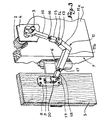
- Fig. 1 is a schematic axial section of a motorization device according to the invention, the control gear motor having been assumed to be embedded inside the opening of the opening with which the movable wall is associated.
- Fig. 2, 3 and 4 illustrate the angular displacement of the movable wall, the parts being shown during the opening movement, in three successive orientations of said wall.
- the reference 1 designates the fixed wall inside which is provided a housing suitable for receiving an electric geared motor 2 whose output shaft 3 protrudes horizontally in front of a cover plate 4.
- This shaft 3 is therefore oriented perpendicular to the pivot axis of the movable wall 5, pivot axis which is in fact materialized by the hinges 6 which ensure the pivotable mounting of this movable wall 5 on the front 7 of the construction.
- a sole 8 which carries a vertical hitch pin or pivot 9, turned downward in the embodiment considered; this pivot 9 is oriented parallel to the axis of the hinges 6, being offset inwards relative to the edge of the movable wall 5 which cooperates with said hinges.
- connection between the pivot 9 and the shaft 3 is effected by means of a coupling mechanism which comprises a crank pin 10 wedged radially on the end of the shaft 3 and associated with a connecting rod 11 with a bent profile, comprising a small vertical arm 11 a and a large horizontal arm 11 b .
- the smaller arm 11 a is axially pierced to receive a pivot 12 which protrudes upward and carries a yoke 13 provided with a transverse axis 14. On the latter is articulated the end of a 15 threaded axially to receive a threaded rod 16, the opposite end of which is itself screwed into a thread axially formed in the crank pin 10. In this way, a system with three articulations (12, 14 and 16) is produced which also allows precise adjustment of the useful length of crankpin 10 for the perfect adaptation of the coupling mechanism.
- the free end of the arm 11b of the bent connecting rod 11 is equipped axially with a threaded rod 17 screwed into a die 18 secured to a longitudinal post engaged on a transverse axis 19; the latter is carried by the two flanges of a yoke 20 provided at the end of the coupling pivot 9.
- a triple articulation (17, 19 and 9) is produced, the axes of which are oriented along three perpendicular planes, this system allowing, moreover, precise adjustment of the useful length of the arm 11b of the bent connecting rod 11.
- the gear motor 2 is of the type used for the electrical operation of blinds or other movable assemblies and consequently includes an automatic declutching mechanism (torque limiter) and a limit switch device associated with the actuation switch.
Landscapes
- Engineering & Computer Science (AREA)
- General Engineering & Computer Science (AREA)
- Mechanical Engineering (AREA)
- Power-Operated Mechanisms For Wings (AREA)
- Catching Or Destruction (AREA)
- Transmission Devices (AREA)
- Gear Transmission (AREA)
- Operating, Guiding And Securing Of Roll- Type Closing Members (AREA)
- Shutters For Cameras (AREA)
- Toys (AREA)
- Food-Manufacturing Devices (AREA)
- Table Devices Or Equipment (AREA)
Claims (3)
- Motorisierungsvorrichtung zur elektrischen Betätigung einer schwenkbar an der feststehenden Wandung (1) eines Mauerausschnitts oder dergleichen befestigten beweglichen wandung (5),
dadurch gekennzeichnet, daß
sie außer einem Elektromotor mit Getriebe (2), der an einer der zwei Wandungen (1 oder 5) derart anbringbar ist, daß seine Abtriebswelle (3) senkrecht zur Schwenkachse der beweglichen Wandung (5) ausgerichtet ist, eine aus einem an der Abtriebswelle (3) festgelegten radialen Kurbelzapfen (10), einer gekrümmten Pleuelstange (11) und einem Kupplungszapfen (9) bestehende Kupplungsvorrichtung umfaßt, die an der anderen Wandung (5 oder 1) parallel zur Drehachse und in einem bestimmten Abstand von dieser anbringbar ist, wobei die Verbindung zwischen jedem der Enden der gekrümmten Pleuelstange (11) und dem Kurbelzapfens (10), beziehungsweise dem Kupplungszapfen (9) ein Dreifachgelenk hat, dessen Achsen in drei verschiedenen, jeweils zueinander senkrecht verlaufenden Ebenen liegen. - Vorrichtung nach Anspruch 1,
dadurch gekennzeichnet, daß
die Verbindung zwischen der gekrümmten Pleuelstange (11) und dem Kurbelzapfen (10) oder dem Zapfen (9) über ein Formstück (15, 18) erfolgt, das am Ende des Kurbelzapfens, beziehungsweise an einem (11b) der beiden Arme der Pleuelstange befestigt ist, wobei das axial bezüglich des es tragenden Teils drehbare Formstück auf der Querachse (14, 19) mit einer Abdeckung (13, 20) gelenkig verbunden ist, die ihrerseits bezüglich der Pleuelstange, beziehungsweise des Kupplungszapfens drehbar ist. - Vorrichtung nach einem der Ansprüche 1 oder 2,
dadurch gekennzeichnet, daß
sie Einrichtungen (16, 17) zum Einstellen der nutzbaren Lange des Kurbelzapfens (10), beziehungsweise der zumindest eines der beiden Arme der gekrümmten Fleuelstange (11) umfaßt.
Applications Claiming Priority (2)
| Application Number | Priority Date | Filing Date | Title |
|---|---|---|---|
| FR9211357A FR2695957B1 (fr) | 1992-09-18 | 1992-09-18 | Dispositif de motorisation pour la manÓoeuvre électrique des volets et autres vantaux pivotants. |
| FR9211357 | 1992-09-18 |
Publications (2)
| Publication Number | Publication Date |
|---|---|
| EP0589806A1 EP0589806A1 (de) | 1994-03-30 |
| EP0589806B1 true EP0589806B1 (de) | 1996-04-24 |
Family
ID=9433814
Family Applications (1)
| Application Number | Title | Priority Date | Filing Date |
|---|---|---|---|
| EP93420373A Expired - Lifetime EP0589806B1 (de) | 1992-09-18 | 1993-09-17 | Elektromotorischer Antrieb für Laden und andere Schwenkflügel |
Country Status (5)
| Country | Link |
|---|---|
| EP (1) | EP0589806B1 (de) |
| AT (1) | ATE137301T1 (de) |
| DE (1) | DE69302347D1 (de) |
| ES (1) | ES2086208T3 (de) |
| FR (1) | FR2695957B1 (de) |
Families Citing this family (2)
| Publication number | Priority date | Publication date | Assignee | Title |
|---|---|---|---|---|
| US5947501A (en) * | 1996-08-29 | 1999-09-07 | Osborn; Robert Kent | Wheelchair attachable transfer board and armrest combination |
| CN114251351B (zh) * | 2022-01-12 | 2024-10-11 | 上海海事大学 | 一种仿生可展开结构及驱动机构 |
Family Cites Families (1)
| Publication number | Priority date | Publication date | Assignee | Title |
|---|---|---|---|---|
| IT1133132B (it) * | 1980-09-23 | 1986-07-09 | Giancarlo Ancellotti | Dispositivo per la chiusura e l'apertura di persiane,scuri e finestre ad incernieramento in genere |
-
1992
- 1992-09-18 FR FR9211357A patent/FR2695957B1/fr not_active Expired - Fee Related
-
1993
- 1993-09-17 ES ES93420373T patent/ES2086208T3/es not_active Expired - Lifetime
- 1993-09-17 DE DE69302347T patent/DE69302347D1/de not_active Expired - Lifetime
- 1993-09-17 AT AT93420373T patent/ATE137301T1/de not_active IP Right Cessation
- 1993-09-17 EP EP93420373A patent/EP0589806B1/de not_active Expired - Lifetime
Also Published As
| Publication number | Publication date |
|---|---|
| FR2695957B1 (fr) | 1994-12-02 |
| EP0589806A1 (de) | 1994-03-30 |
| ES2086208T3 (es) | 1996-06-16 |
| DE69302347D1 (de) | 1996-05-30 |
| ATE137301T1 (de) | 1996-05-15 |
| FR2695957A1 (fr) | 1994-03-25 |
Similar Documents
| Publication | Publication Date | Title |
|---|---|---|
| EP2152570A2 (de) | Tauchfähiges gerät mit flexiblen wasserdichten membranen | |
| EP0484258A1 (de) | Öffnungs- und Schliessvorrichtung einer Flügel drehbar auf 180 Graden und solche Vorrichtung umfassende Anlage | |
| FR3005680A1 (fr) | Volet brise soleil motorise | |
| EP0589806A1 (de) | Elektromotorischer Antrieb für Laden und andere Schwenkflügel | |
| EP0438364A1 (de) | Drehantriebsvorrichtung für den Schrankenbaum einer beweglichen Schranke | |
| FR2758520A1 (fr) | Systeme de porte, en particulier pour un avion version passagers | |
| EP0908352B1 (de) | Vorrichtung zum Einstellen der Neigung eines Kfz-Scheinwerfers | |
| FR2591650A1 (fr) | Dispositif de manoeuvre pour volets ou persiennes a un ou deux vantaux pivotants | |
| FR2646202A1 (fr) | Dispositif de manoeuvre pour l'ouverture et la fermeture d'au moins un volet | |
| FR2689171A1 (fr) | Dispositif de commande d'un vantail de porte ou portail. | |
| FR2508530A1 (fr) | Systeme destine a la fermeture et/ou a l'ouverture d'un battant en particulier d'un battant de porte ou de portail | |
| FR2718165A1 (fr) | Dispositif d'entraînement en rotation d'une barrière mobile. | |
| FR2807781A1 (fr) | Bati dormant comprenant un ensemble d'entrainement de volets battants | |
| EP0352206B1 (de) | nager für Kipp- oder Schwingdachfenster | |
| FR2711726A1 (fr) | Dispositif de commande d'une fenêtre à lames orientables du type jalousie. | |
| FR2649747A1 (fr) | Automate de manoeuvre de portail automatique | |
| FR2653157A1 (fr) | Porte a deplacement lateral a panneaux articules avec manóoeuvre electrique. | |
| EP0301960B1 (de) | Antriebsvorrichtung für einen beweglichen Flügel | |
| FR3166920A1 (fr) | Volet à lames orientables motorisé | |
| EP1038081A1 (de) | Verriegelungsvorrichtung für die hinterkante einer kraftfahrzeugschiebetür | |
| EP0876946A1 (de) | Türschliesser, damit ausgerüstete Tür und Schienenfahrzeug mit mindestens einer derartigen Vorrichtung und/oder Tür | |
| FR2820164A1 (fr) | Systeme d'ouverture et de fermeture automatique pour une porte pliante et porte equipee d'un tel systeme | |
| WO2007051815A2 (fr) | Pilier pour ouvrir ou fermer automatiquement un vantail et portail comprenant un tel pilier | |
| FR2776008A3 (fr) | Dispositif d'ouverture et de fermeture de portail a battants | |
| FR2928169A1 (fr) | Ensemble d'ouverture et de fermeture motorisee pour ouvrant/battant |
Legal Events
| Date | Code | Title | Description |
|---|---|---|---|
| PUAI | Public reference made under article 153(3) epc to a published international application that has entered the european phase |
Free format text: ORIGINAL CODE: 0009012 |
|
| AK | Designated contracting states |
Kind code of ref document: A1 Designated state(s): AT BE CH DE DK ES FR GB GR IE IT LI LU MC NL PT SE |
|
| 17P | Request for examination filed |
Effective date: 19940622 |
|
| 17Q | First examination report despatched |
Effective date: 19950721 |
|
| GRAH | Despatch of communication of intention to grant a patent |
Free format text: ORIGINAL CODE: EPIDOS IGRA |
|
| GRAA | (expected) grant |
Free format text: ORIGINAL CODE: 0009210 |
|
| AK | Designated contracting states |
Kind code of ref document: B1 Designated state(s): AT BE CH DE DK ES FR GB GR IE IT LI LU MC NL PT SE |
|
| PG25 | Lapsed in a contracting state [announced via postgrant information from national office to epo] |
Ref country code: NL Free format text: LAPSE BECAUSE OF FAILURE TO SUBMIT A TRANSLATION OF THE DESCRIPTION OR TO PAY THE FEE WITHIN THE PRESCRIBED TIME-LIMIT Effective date: 19960424 Ref country code: GR Free format text: LAPSE BECAUSE OF FAILURE TO SUBMIT A TRANSLATION OF THE DESCRIPTION OR TO PAY THE FEE WITHIN THE PRESCRIBED TIME-LIMIT Effective date: 19960424 Ref country code: GB Effective date: 19960424 Ref country code: DK Effective date: 19960424 Ref country code: AT Effective date: 19960424 |
|
| REF | Corresponds to: |
Ref document number: 137301 Country of ref document: AT Date of ref document: 19960515 Kind code of ref document: T |
|
| REG | Reference to a national code |
Ref country code: IE Ref legal event code: FG4D Free format text: 68116 |
|
| REF | Corresponds to: |
Ref document number: 69302347 Country of ref document: DE Date of ref document: 19960530 |
|
| REG | Reference to a national code |
Ref country code: ES Ref legal event code: FG2A Ref document number: 2086208 Country of ref document: ES Kind code of ref document: T3 |
|
| ITF | It: translation for a ep patent filed | ||
| PG25 | Lapsed in a contracting state [announced via postgrant information from national office to epo] |
Ref country code: SE Effective date: 19960724 Ref country code: PT Effective date: 19960724 |
|
| PG25 | Lapsed in a contracting state [announced via postgrant information from national office to epo] |
Ref country code: DE Effective date: 19960725 |
|
| PG25 | Lapsed in a contracting state [announced via postgrant information from national office to epo] |
Ref country code: LU Free format text: LAPSE BECAUSE OF NON-PAYMENT OF DUE FEES Effective date: 19960930 Ref country code: LI Effective date: 19960930 Ref country code: CH Effective date: 19960930 |
|
| NLV1 | Nl: lapsed or annulled due to failure to fulfill the requirements of art. 29p and 29m of the patents act | ||
| GBV | Gb: ep patent (uk) treated as always having been void in accordance with gb section 77(7)/1977 [no translation filed] |
Effective date: 19960424 |
|
| PG25 | Lapsed in a contracting state [announced via postgrant information from national office to epo] |
Ref country code: IE Free format text: LAPSE BECAUSE OF NON-PAYMENT OF DUE FEES Effective date: 19961107 |
|
| REG | Reference to a national code |
Ref country code: IE Ref legal event code: FD4D Ref document number: 68116 Country of ref document: IE |
|
| PLBE | No opposition filed within time limit |
Free format text: ORIGINAL CODE: 0009261 |
|
| STAA | Information on the status of an ep patent application or granted ep patent |
Free format text: STATUS: NO OPPOSITION FILED WITHIN TIME LIMIT |
|
| PG25 | Lapsed in a contracting state [announced via postgrant information from national office to epo] |
Ref country code: MC Effective date: 19970331 |
|
| 26N | No opposition filed | ||
| REG | Reference to a national code |
Ref country code: CH Ref legal event code: PL |
|
| PGFP | Annual fee paid to national office [announced via postgrant information from national office to epo] |
Ref country code: BE Payment date: 20001011 Year of fee payment: 8 |
|
| PG25 | Lapsed in a contracting state [announced via postgrant information from national office to epo] |
Ref country code: BE Free format text: LAPSE BECAUSE OF NON-PAYMENT OF DUE FEES Effective date: 20010930 |
|
| BERE | Be: lapsed |
Effective date: 20010930 |
|
| PGFP | Annual fee paid to national office [announced via postgrant information from national office to epo] |
Ref country code: ES Payment date: 20050916 Year of fee payment: 13 |
|
| PGFP | Annual fee paid to national office [announced via postgrant information from national office to epo] |
Ref country code: FR Payment date: 20060727 Year of fee payment: 14 |
|
| PGFP | Annual fee paid to national office [announced via postgrant information from national office to epo] |
Ref country code: IT Payment date: 20060930 Year of fee payment: 14 |
|
| REG | Reference to a national code |
Ref country code: FR Ref legal event code: ST Effective date: 20080531 |
|
| PG25 | Lapsed in a contracting state [announced via postgrant information from national office to epo] |
Ref country code: FR Free format text: LAPSE BECAUSE OF NON-PAYMENT OF DUE FEES Effective date: 20071001 |
|
| REG | Reference to a national code |
Ref country code: ES Ref legal event code: FD2A Effective date: 20070918 |
|
| PG25 | Lapsed in a contracting state [announced via postgrant information from national office to epo] |
Ref country code: ES Free format text: LAPSE BECAUSE OF NON-PAYMENT OF DUE FEES Effective date: 20070918 |
|
| PG25 | Lapsed in a contracting state [announced via postgrant information from national office to epo] |
Ref country code: IT Free format text: LAPSE BECAUSE OF NON-PAYMENT OF DUE FEES Effective date: 20070917 |