EP0590103B1 - Appareil de regulation de la combustion, de la pollution et des reactions chimiques - Google Patents
Appareil de regulation de la combustion, de la pollution et des reactions chimiques Download PDFInfo
- Publication number
- EP0590103B1 EP0590103B1 EP93901025A EP93901025A EP0590103B1 EP 0590103 B1 EP0590103 B1 EP 0590103B1 EP 93901025 A EP93901025 A EP 93901025A EP 93901025 A EP93901025 A EP 93901025A EP 0590103 B1 EP0590103 B1 EP 0590103B1
- Authority
- EP
- European Patent Office
- Prior art keywords
- light
- combustion
- temperature
- particles
- wavelength
- Prior art date
- Legal status (The legal status is an assumption and is not a legal conclusion. Google has not performed a legal analysis and makes no representation as to the accuracy of the status listed.)
- Expired - Lifetime
Links
- 238000002485 combustion reaction Methods 0.000 title claims abstract description 90
- 238000001311 chemical methods and process Methods 0.000 title description 7
- 239000002245 particle Substances 0.000 claims abstract description 89
- 238000012546 transfer Methods 0.000 claims abstract description 32
- 230000001105 regulatory effect Effects 0.000 claims abstract description 6
- 239000007789 gas Substances 0.000 claims description 70
- 239000004071 soot Substances 0.000 claims description 27
- 238000000034 method Methods 0.000 claims description 24
- 239000000446 fuel Substances 0.000 claims description 21
- 230000005855 radiation Effects 0.000 claims description 20
- 238000007664 blowing Methods 0.000 claims description 19
- 239000003245 coal Substances 0.000 claims description 17
- 230000001276 controlling effect Effects 0.000 claims description 12
- 229910052500 inorganic mineral Inorganic materials 0.000 claims description 12
- 239000011707 mineral Substances 0.000 claims description 12
- XLYOFNOQVPJJNP-UHFFFAOYSA-N water Substances O XLYOFNOQVPJJNP-UHFFFAOYSA-N 0.000 claims description 11
- QGZKDVFQNNGYKY-UHFFFAOYSA-N Ammonia Chemical compound N QGZKDVFQNNGYKY-UHFFFAOYSA-N 0.000 claims description 10
- 150000001875 compounds Chemical class 0.000 claims description 8
- 239000013307 optical fiber Substances 0.000 claims description 8
- 238000004458 analytical method Methods 0.000 claims description 7
- 239000000126 substance Substances 0.000 claims description 7
- 238000004140 cleaning Methods 0.000 claims description 6
- 229910021529 ammonia Inorganic materials 0.000 claims description 5
- XSQUKJJJFZCRTK-UHFFFAOYSA-N Urea Chemical compound NC(N)=O XSQUKJJJFZCRTK-UHFFFAOYSA-N 0.000 claims description 4
- 239000004202 carbamide Substances 0.000 claims description 4
- 239000002910 solid waste Substances 0.000 claims description 3
- 238000001514 detection method Methods 0.000 claims description 2
- 230000000977 initiatory effect Effects 0.000 claims 1
- 238000009434 installation Methods 0.000 claims 1
- 230000008859 change Effects 0.000 abstract description 15
- 239000002956 ash Substances 0.000 description 42
- 230000003287 optical effect Effects 0.000 description 36
- 238000005259 measurement Methods 0.000 description 19
- 230000000694 effects Effects 0.000 description 10
- 238000009826 distribution Methods 0.000 description 6
- 230000006870 function Effects 0.000 description 6
- 239000000523 sample Substances 0.000 description 6
- 238000012360 testing method Methods 0.000 description 6
- 239000002699 waste material Substances 0.000 description 6
- 238000009529 body temperature measurement Methods 0.000 description 5
- 230000003247 decreasing effect Effects 0.000 description 5
- 230000001419 dependent effect Effects 0.000 description 5
- 238000012544 monitoring process Methods 0.000 description 5
- 230000009467 reduction Effects 0.000 description 5
- 239000002893 slag Substances 0.000 description 5
- MWUXSHHQAYIFBG-UHFFFAOYSA-N Nitric oxide Chemical compound O=[N] MWUXSHHQAYIFBG-UHFFFAOYSA-N 0.000 description 4
- 238000006243 chemical reaction Methods 0.000 description 4
- 230000006378 damage Effects 0.000 description 4
- 239000003344 environmental pollutant Substances 0.000 description 4
- VNWKTOKETHGBQD-UHFFFAOYSA-N methane Chemical compound C VNWKTOKETHGBQD-UHFFFAOYSA-N 0.000 description 4
- 231100000719 pollutant Toxicity 0.000 description 4
- 239000000047 product Substances 0.000 description 4
- OYPRJOBELJOOCE-UHFFFAOYSA-N Calcium Chemical compound [Ca] OYPRJOBELJOOCE-UHFFFAOYSA-N 0.000 description 3
- 238000004616 Pyrometry Methods 0.000 description 3
- 239000011575 calcium Substances 0.000 description 3
- 229910052791 calcium Inorganic materials 0.000 description 3
- 238000004364 calculation method Methods 0.000 description 3
- 239000003086 colorant Substances 0.000 description 3
- 230000008021 deposition Effects 0.000 description 3
- 238000013461 design Methods 0.000 description 3
- 238000004519 manufacturing process Methods 0.000 description 3
- 238000010248 power generation Methods 0.000 description 3
- 230000004044 response Effects 0.000 description 3
- QVGXLLKOCUKJST-UHFFFAOYSA-N atomic oxygen Chemical compound [O] QVGXLLKOCUKJST-UHFFFAOYSA-N 0.000 description 2
- 239000006227 byproduct Substances 0.000 description 2
- 239000010883 coal ash Substances 0.000 description 2
- 239000000567 combustion gas Substances 0.000 description 2
- 239000000498 cooling water Substances 0.000 description 2
- 230000003628 erosive effect Effects 0.000 description 2
- 239000000835 fiber Substances 0.000 description 2
- 239000012530 fluid Substances 0.000 description 2
- 239000000203 mixture Substances 0.000 description 2
- 238000012806 monitoring device Methods 0.000 description 2
- 239000003345 natural gas Substances 0.000 description 2
- 239000001301 oxygen Substances 0.000 description 2
- 229910052760 oxygen Inorganic materials 0.000 description 2
- BASFCYQUMIYNBI-UHFFFAOYSA-N platinum Chemical compound [Pt] BASFCYQUMIYNBI-UHFFFAOYSA-N 0.000 description 2
- 238000012545 processing Methods 0.000 description 2
- 238000010926 purge Methods 0.000 description 2
- 230000035945 sensitivity Effects 0.000 description 2
- 239000007787 solid Substances 0.000 description 2
- 239000003476 subbituminous coal Substances 0.000 description 2
- 238000013519 translation Methods 0.000 description 2
- 239000002912 waste gas Substances 0.000 description 2
- 238000012935 Averaging Methods 0.000 description 1
- 239000002028 Biomass Substances 0.000 description 1
- 235000002918 Fraxinus excelsior Nutrition 0.000 description 1
- UFHFLCQGNIYNRP-UHFFFAOYSA-N Hydrogen Chemical compound [H][H] UFHFLCQGNIYNRP-UHFFFAOYSA-N 0.000 description 1
- FYYHWMGAXLPEAU-UHFFFAOYSA-N Magnesium Chemical compound [Mg] FYYHWMGAXLPEAU-UHFFFAOYSA-N 0.000 description 1
- ODUCDPQEXGNKDN-UHFFFAOYSA-N Nitrogen oxide(NO) Natural products O=N ODUCDPQEXGNKDN-UHFFFAOYSA-N 0.000 description 1
- 206010067482 No adverse event Diseases 0.000 description 1
- XUIMIQQOPSSXEZ-UHFFFAOYSA-N Silicon Chemical compound [Si] XUIMIQQOPSSXEZ-UHFFFAOYSA-N 0.000 description 1
- 229910000831 Steel Inorganic materials 0.000 description 1
- 238000010521 absorption reaction Methods 0.000 description 1
- 230000003213 activating effect Effects 0.000 description 1
- 230000008901 benefit Effects 0.000 description 1
- 230000008033 biological extinction Effects 0.000 description 1
- 230000005540 biological transmission Effects 0.000 description 1
- 239000002802 bituminous coal Substances 0.000 description 1
- 239000003575 carbonaceous material Substances 0.000 description 1
- 230000015556 catabolic process Effects 0.000 description 1
- 239000011248 coating agent Substances 0.000 description 1
- 238000000576 coating method Methods 0.000 description 1
- 239000010849 combustible waste Substances 0.000 description 1
- 230000000295 complement effect Effects 0.000 description 1
- 238000009833 condensation Methods 0.000 description 1
- 230000005494 condensation Effects 0.000 description 1
- 239000004020 conductor Substances 0.000 description 1
- 230000003292 diminished effect Effects 0.000 description 1
- 239000006185 dispersion Substances 0.000 description 1
- 239000000428 dust Substances 0.000 description 1
- 230000005611 electricity Effects 0.000 description 1
- 238000010304 firing Methods 0.000 description 1
- 239000003546 flue gas Substances 0.000 description 1
- 239000002803 fossil fuel Substances 0.000 description 1
- 239000000295 fuel oil Substances 0.000 description 1
- 239000011521 glass Substances 0.000 description 1
- 238000010438 heat treatment Methods 0.000 description 1
- 229930195733 hydrocarbon Natural products 0.000 description 1
- 150000002430 hydrocarbons Chemical class 0.000 description 1
- 239000001257 hydrogen Substances 0.000 description 1
- 229910052739 hydrogen Inorganic materials 0.000 description 1
- 230000006872 improvement Effects 0.000 description 1
- 238000002347 injection Methods 0.000 description 1
- 239000007924 injection Substances 0.000 description 1
- 230000002452 interceptive effect Effects 0.000 description 1
- 238000011068 loading method Methods 0.000 description 1
- 239000011777 magnesium Substances 0.000 description 1
- 229910052749 magnesium Inorganic materials 0.000 description 1
- 238000013507 mapping Methods 0.000 description 1
- 239000011159 matrix material Substances 0.000 description 1
- 230000007935 neutral effect Effects 0.000 description 1
- 239000003921 oil Substances 0.000 description 1
- 229910052697 platinum Inorganic materials 0.000 description 1
- PXXKQOPKNFECSZ-UHFFFAOYSA-N platinum rhodium Chemical compound [Rh].[Pt] PXXKQOPKNFECSZ-UHFFFAOYSA-N 0.000 description 1
- 239000000843 powder Substances 0.000 description 1
- 230000008569 process Effects 0.000 description 1
- 230000003134 recirculating effect Effects 0.000 description 1
- 238000011084 recovery Methods 0.000 description 1
- 230000002829 reductive effect Effects 0.000 description 1
- 238000007670 refining Methods 0.000 description 1
- 238000002310 reflectometry Methods 0.000 description 1
- 238000009877 rendering Methods 0.000 description 1
- 229910052710 silicon Inorganic materials 0.000 description 1
- 239000010703 silicon Substances 0.000 description 1
- 230000003595 spectral effect Effects 0.000 description 1
- 239000010959 steel Substances 0.000 description 1
- 230000000153 supplemental effect Effects 0.000 description 1
- 231100000331 toxic Toxicity 0.000 description 1
- 230000002588 toxic effect Effects 0.000 description 1
- 238000002834 transmittance Methods 0.000 description 1
Images




Classifications
-
- F—MECHANICAL ENGINEERING; LIGHTING; HEATING; WEAPONS; BLASTING
- F23—COMBUSTION APPARATUS; COMBUSTION PROCESSES
- F23N—REGULATING OR CONTROLLING COMBUSTION
- F23N5/00—Systems for controlling combustion
- F23N5/003—Systems for controlling combustion using detectors sensitive to combustion gas properties
-
- F—MECHANICAL ENGINEERING; LIGHTING; HEATING; WEAPONS; BLASTING
- F23—COMBUSTION APPARATUS; COMBUSTION PROCESSES
- F23N—REGULATING OR CONTROLLING COMBUSTION
- F23N5/00—Systems for controlling combustion
- F23N5/02—Systems for controlling combustion using devices responsive to thermal changes or to thermal expansion of a medium
- F23N5/08—Systems for controlling combustion using devices responsive to thermal changes or to thermal expansion of a medium using light-sensitive elements
- F23N5/082—Systems for controlling combustion using devices responsive to thermal changes or to thermal expansion of a medium using light-sensitive elements using electronic means
-
- F—MECHANICAL ENGINEERING; LIGHTING; HEATING; WEAPONS; BLASTING
- F23—COMBUSTION APPARATUS; COMBUSTION PROCESSES
- F23N—REGULATING OR CONTROLLING COMBUSTION
- F23N2225/00—Measuring
- F23N2225/08—Measuring temperature
- F23N2225/10—Measuring temperature stack temperature
-
- F—MECHANICAL ENGINEERING; LIGHTING; HEATING; WEAPONS; BLASTING
- F23—COMBUSTION APPARATUS; COMBUSTION PROCESSES
- F23N—REGULATING OR CONTROLLING COMBUSTION
- F23N5/00—Systems for controlling combustion
- F23N5/02—Systems for controlling combustion using devices responsive to thermal changes or to thermal expansion of a medium
- F23N5/08—Systems for controlling combustion using devices responsive to thermal changes or to thermal expansion of a medium using light-sensitive elements
Definitions
- the present invention relates to a system and a method for controlling one or more operating parameters of a combustion process in a combustion chamber or the thermal efficiency in a boiler having a combustion chamber and a heat exchange surface.
- Combustion of carbonaceous materials is the dominant source of energy in today's industrial society.
- the primary products of combustion are heat, gases and ash. Heat generated by combustion is transferred to a working fluid, such as steam (making the system a "boiler"), which is then transported to a location where it is used to power turbines to produce electricity, drive chemical processes or provide a source of heat.
- Combustion is also used to incinerate solid municipal wastes. In this case, the primary product is the destruction of the waste, although some "waste-to-energy" systems make practical use of the heat generated by incineration.
- Combustion gases from boilers and incinerators are injected into the atmosphere after recovering as much heat as possible.
- a typical boiler collects heat from both the combustion or furnace section and from the exhaust gas stream. Heat transfer in the furnace is primarily by absorption of the heat by water-cooled walls or tubing.
- the fraction of heat recovered is maximized when a particular temperature distribution is maintained within the boiler and its downstream recovery apparatus.
- combustion temperatures or heat transfer temperatures deviate from this range, more heat is lost up the stack. This occurs, for example, when soot or slag builds up on the heat exchange surfaces of the combustion chamber thereby reducing the efficient transfer of heat to the boiler.
- Incinerators for waste to energy production or for waste destruction must maintain combustion temperatures in a specified range in order to reduce the risk of emission of significant quantities of toxic hydrocarbons and/or chlorinated compounds. Exhaust gas temperatures are generally not monitored in these facilities, therefore procedures for assuring that these temperature requirements are met require use of excessive, and thus wasteful auxiliary fuels.
- Certain pollution control systems for boilers or incinerators use a chemical process in the post-combustion zone to reduce the concentration of harmful pollutants. These systems inject urea, ammonia, or other compounds that react chemically with the harmful pollutants in the gas stream, rendering them benign. The reaction occurs within an optimum temperature range. Should these reactions occur at temperatures outside of the optimum range, the pollution reduction could be inadequate and other harmful compounds could be produced.
- One of the parameters used to measure and control the efficiency of a boiler is the temperature of the gas exiting the combustion chamber.
- the exit gas temperature be between about 1000°K to 1800°K.
- the combustion conditions can be changed to increase the temperature.
- the heat transfer surfaces can be cleaned to improve heat transfer to the boiler.
- an auxiliary heater is often used to control the temperature of combustion in solid waste incinerators. It is desirable to fire the auxiliary heaters only when necessary and only to the extent required to keep the combustion temperature within the desired range for maximum efficiency.
- thermocouple probes also known as high-velocity thermocouple probes
- These devices are essentially thermocouples shielded by water-cooled tubular housings through which the hot exhaust gas is drawn. These devices are difficult to use and are not accurate unless the thermocouple junction is well shielded from the colder furnace walls. The thermocouples cannot withstand continuous exposure to the hot gases, and generally succumb to erosion and breakdown. Another drawback is that these devices only provide a single point measurement, so that several devices must be used to obtain an average gas temperature.
- Acoustic pyrometers have been used to monitor exit gas temperatures. Acoustic pyrometers are based on the premise that the change in the temperature of the gas can be related to the change in the speed of sound. These devices take a measurement across a line of sight to compute an average temperature. Acoustic temperature measurement assumes that the gas molecular weight is fairly constant. In practice, however, the amount of moisture and the hydrogen content in the fuel can vary significantly, which renders sonic measurements less accurate. Another drawback is that the acoustic horns used in these devices are subjected to extremely high temperatures and soot and ash deposits which change their sound characteristics. For accurate temperature mapping, multiple horns and detectors are required. In addition, turbulence in the system cause dispersion of the particles, and acoustic emissions from combustion related equipment introduces background noise both of which reduce the accuracy of the measurements. Sonic measurement is costly and complex, and requires time consuming signal analysis.
- Infrared optical pyrometers also have been used to monitor exit gas temperatures. These pyrometers measure infrared radiation in the boiler exit chamber. However, they cannot distinguish between infrared radiation emitted by the gas and that radiating from the cooler furnace walls, thus, optical infrared pyrometers are not sufficiently accurate for use in industrial monitoring and control systems.
- JP-A-63-217,130 describes a method of maintaining a combustion state of burners by measuring the waste gas distribution at the outlet port of a boiler. This is accomplished by measuring light intensity of the flame of a burner. The system further discloses a waste gas analyzer in which the concentration of oxygen is analyzed to discover the combustion state of the associated burner.
- US-A-4,644,173 describes a flame analyzer in which a monochromator is used to disperse light from a flame into its component wavelengths for measurement of temperature and particle distribution about the flame.
- JP-A-61-289,226 describes a means for determining temperature distribution around a burner, ascertained by using light that is fibre optically transmitted through a fibre disposed on a burner and analyzing the dispersed light with a spectroscopic analyzer. Then the combustion is examined to determine the degree of swirling of combustion air.
- This system incorporates a gas analyzer for determining the composition of combustion gas products.
- the present invention relates to a system and a method as defined in the appended independent claims.
- the system comprises a means for detecting the intensity of light within a preselected, narrow band of wavelengths emitted from ash particles entrained in the combustion product gas stream and a means for generating a signal indicative of the intensity of light detected.
- Means responsive to the signal are used for controlling a combustion parameter in an incinerator, regulating heat-transfer in a boiler, or for operating pollution control or other chemical process equipment.
- the band of wavelengths detected is preferably within the range of from about 400nm to about 900nm and preferably has a bandwidth of about 10nm to about 12nm. Variations in the absolute or relative intensity of the light within these bands is indicative of temperature changes which, for example, indicate thermal inefficiency in the boiler.
- an increase in the intensity of light emitted from the particles in the selected band of wavelengths indicates an undesirable increase in the temperature of the particles, and thus, of the gas with which they are in equilibrium.
- This temperature increase in turn indicates that inefficient heat transfer is taking place in the boiler, e.g., due to soot or slag build-up on the heat exchange surfaces.
- a signal indicative of the intensity of light detected, and thus, the temperature of the gas stream is generated. This signal is used to compute the temperature, which then is transmitted to an operator or to a computer controlled device which activates a means to clean the slag, soot or other deposits from the heat exchange surfaces in the boiler, such as a water lance or soot blower, thereby restoring efficient heat exchange in the boiler.
- the system of the present invention provides a method for determining and monitoring exit gas temperatures in situations where highly reflective particles are produced, for example, by combustion of fuels having a high mineral content where the minerals are predominantly associated with the organic matrix of the fuel. For example, many coals are rich in calcium, magnesium and other minerals which form a reflective coating on ash particles upon combustion of the coals. This reflected light can overwhelm the light emitted by the ash particles which is indicative of the temperature, thereby compromising the accuracy of the temperature readings.
- the present system comprises selectively measuring particular wavelengths of light emitted by reflective particles having a particle size conducive to forward scattering of the reflected light. This technique permits the present device to discriminate between light reflected by and light emitted from the particles. As in the above-described system, the intensities of the wavelengths detected are indicative of the temperature of the exit gas, which can be used to monitor the efficiency of the combustion process.
- the present invention provides an accurate system for monitoring efficiency, e.g., the combustion conditions in an incinerator or heat transfer conditions in a boiler.
- the present invention can be used to monitor and regulate pollution control systems to maximize efficiency of the systems and thereby reduce emission of pollutants.
- the optical monitoring device of the present invention can be integrated into a computer or microprocessor-controlled feedback system which automatically activates a secondary system for auxiliary burning or cleaning of the heat exchange surfaces when the temperature rises or falls outside of the optimal range.
- the system provides real-time, accurate readings of furnace exit gas temperatures which are substantially free of interference or background noise resulting from the furnace walls or from reflected light, and means for controlling operating parameters to optimize efficient combustion and minimize undesirable emissions.
- Figure 1 is a schematic illustration of an optical temperature monitor useful in the apparatus of the invention.
- Figure 2 is a schematic illustration showing the present system installed in the furnace exit of a boiler.
- Figure 3 is a graph showing the furnace exit gas temperature (FEGT) temperature in a coal-fired boiler during operation.
- FEGT furnace exit gas temperature
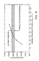
- Figure 4 is a graph showing the FEGT temperature in a coal-fired boiler as detected by the present optical monitor system compared to the temperatures detected by an HVT probe.
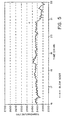
- Figure 5 is a graph showing the change in temperature obtained using the present optical monitor system before, during and after one soot blowing operation.
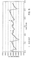
- Figure 6 is a graph showing the change in temperature obtained using the present optical monitor system before, during and after several soot blowing operations.
- Figure 7 is a graph showing the temperature vs. wavelength vs. emissivity obtained using an optical temperature monitor system in a power plant burning low mineral content Eastern bituminous coal.
- Figure 8 is a graph showing the temperatures measured during two 24 hour periods using a three-color pyrometer which had not been optimized for use with reflective particles in a power plant burning Western sub-bituminous coal having a high level of organic-associated calcium. These data showed the temperature to be much higher than expected indicating that reflected light was interfering with accurate temperature measurement.
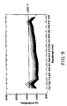
- Figure 9 is a graph showing the temperature vs. wavelength vs. emissivity obtained using an optical temperature monitor modified to discriminate between reflected light and emitted light. The temperature was within the expected range.
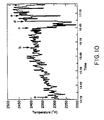
- Figure 10 is a graph showing the change in temperature obtained using the present optical temperature monitor system before, during and after a soot blowing operation in a power plant burning Western high-mineral coal.
- the present invention provides a system for detecting the intensities of selected narrow bands of wavelengths of light emitted by ash particles entrained in the gas stream which results from combustion of fuels in a boiler or an incinerator; for processing a signal generated in response to the light which is detected; and for utilizing the signal to regulate the thermal efficiency or other critical operational parameters the boiler or incinerator.
- the intensity of the light in certain wavelengths emitted by the ash particles is indicative of the temperature of the particles.
- the ash particles are typically about 20 to 30 microns in diameter and in thermal equilibrium with the surrounding gas within tens of microseconds, thus, an accurate measurement of the temperature of the gas stream as it exits the furnaces can be obtained from the particles.
- Figure 1 shows a schematic representation of an optical temperature monitor 10 according to the present invention.
- the monitor includes an aperture tube 16 which is inserted into an observation port suitably positioned in a furnace or stack wall 18.
- the aperture tube 16 preferably is surrounded by a water-cooled jacket 20.
- the device is preferably contained within an air-cooled dust-tight enclosure 14 having an air inlet 64.
- the enclosure 14 can also contain cooling water inlet 22 and outlet 24 for providing cooling water through a conductor (not shown) to the water jacket 20. Dotted lines 50 represent the light path.
- the tube preferably contains air inlets 36.
- air inlets 36 are located in front of lens 26 as shown, and are positioned to direct an air flow from air inlet 64 over the surface of lens 26. The air then exits the tube into the furnace exhaust, thereby creating positive pressure in front of lens 26, which keeps soot and ash particles from being deposited on the lens.
- Other means of cleaning lens 26, for example a closable shutter or device which wipes the surface clean periodically, can also be used for this purpose.
- the device according to the present invention contains at least one photodetector and at least one field lens and/or optical fiber.
- a preferred configuration contains two or more field lenses or optical fibers and photodetectors.
- the photodetectors are serviced by filters which exclude light having wavelengths outside the range of from about 400nm to about 900nm.
- Each photodetector is filtered to detect a narrow band of wavelengths, or colors, which if more than one photodetector is used, is different from that detected by the other photodetector(s).
- the light shown by dotted lines 50 which is emitted from ash particles is imaged by lens 26 then passes through aperture 28 and is re-imaged by field lenses 30 onto photodetectors 32.
- Interference filters 34 preferably located between the field lenses 30, or the optical fibers, and photodetectors 32, limit the light striking each of the photodetectors 32 to the desired wavelengths.
- the wavelengths are selected to diminish or negate radiation emitted by the furnace walls and/or reflected light as disclosed herein.
- Preferred wavelengths are those in the visible to near IR range, from about 400nm to about 900nm.
- three photodetectors which detect a specific band of wavelengths having a bandwidth of about 10nm to 12nm centered at 600, 650 and 700nm, respectively are used.
- two photodetectors which detect a specific band of wavelengths having a bandwidth of about 10nm to 12nm centered at 430nm and 730nm, respectively are used. All other light is filtered out by interference filters 34.
- Photodetectors 32 generate a signal which is indicative of the absolute or relative intensities of the wavelengths of light which strike them. This signal is transported to a processing unit which generates a signal indicative of the temperatures of the ash particles, as shown in Figure 2.
- FIG 2 schematically illustrates the present system mounted in the furnace exit area of a boiler.
- an enclosure 14 containing the optics is mounted on the furnace exhaust stack 15 so that aperture tube 16 traverses the furnace wall.
- the device is mounted just above combustion chamber 42 and is located such that it is above flame zone 44 where the hot gas stream exits the combustion zone. Ash particles 48 resulting from combustion of the fuel are entrained in gas stream 46.
- the intensities of light having the selected wavelengths are converted by the photodetectors into signals which are directed through signal paths 52 into a signal processor 54.
- Signal processor 54 is preferably integrated into enclosure 14.
- Signal processor 54 analyzes the signals and, optionally, computes the temperature of ash particles 48 based on the data. Analysis of the spectral distribution of the radiant energy emitted from the particles enables a computation of the temperature of the gas stream.
- analog signals emitted by the photodetectors are amplified and transmitted to an analog-to-digital converter. The digitized signals are then communicated to a computer which computes the temperature of the particles based on the signals.
- the temperature data can then be transported via line 61 to a display unit 62 which displays the temperature or time course thereof, or other indicia, thereby prompting an operator to perform an activity to regulate combustion and/or heat transfer.
- the signal from processor 54 can be delivered via line 63 to actuate an automated control unit 60 which regulates one or more combustion or heat transfer parameters, e.g., starts an auxiliary burner, or controls a soot blower or a water lance servicing combustion chamber 42.
- the system of the present invention provides a method to determine and monitor exit gas temperatures in situations where highly reflective ash particles are produced by combustion of fuels having a high mineral content.
- Reflective particles entrained in the gas stream can skew measurements taken by optical detectors by reflecting light from the flame in the combustion chamber. This reflected light can overwhelm the light emitted by the ash particles which is indicative of the temperature, thereby compromising the accuracy of the temperature readings.
- the present system comprises selectively measuring particular wavelengths of light emitted by reflective particles having a particle size conducive to forward scattering of the reflected light at these wavelengths. This technique permits the present device to discriminate between light reflected by and light emitted from the ash particles.
- the detection means comprises at least one photodetector which detects light having a band of wavelengths of from about 400nm to about 800nm having a bandwidth of about 10nm to 12nm. If more than one photodetector is used, each photodetector detects a different band of wavelengths.
- a pyrometer equipped with at least two photodectors which detect a band of wavelengths of light centered at 430nm and 730nm, respectively, is used. The ratio of the intensities of light detected by this pyrometer provides an accurate temperature reading, particularly when reflective particles are present, although it can be used in systems having either reflective or non-reflective particles.
- B i A ⁇ C 1 t i ⁇ i / ⁇ i 5 is a constant (independent of temperature) that is determined by the optical system and may be evaluated by calibration.
- Equation (2) cannot be used directly to evaluate the particle-laden gas temperature without careful consideration of the effects of these temperature differences.
- the particle-laden gas is of uniform temperature and radiates as a partially transparent hot volume with temperature T P
- the cooler walls radiate like a blackbody with temperature T w .
- the radiant energy incident upon the pyrometer's aperture can then be considered to be the sum of the separate contributions from the particles in the gas and from the walls, taking into account the fact that the particles partially obscure the walls.
- the innovative key to the present system is to select wavelengths that, under typical furnace operating conditions, make the radiant energy contributions from the walls insignificant compared to those from the particles, and then to use Equation (2) to determine the temperature.
- Equation (3) shows that if T w ⁇ T p , then the contribution of the second term, representing the wall radiation, can be made negligibly small compared to the particle radiation manifested in the first term by selecting a sufficiently short wavelength.
- ⁇ i is the effective emissivity of the ash cloud and is roughly the same magnitude as f p .
- the radiant power emitted by the ash cloud increases faster than exponentially with temperature, but is only linearly dependent on emissivity.
- a relatively large uncertainty in emissivity causes only a small error in temperature.
- the key to accurately measuring furnace exhaust gas temperatures is to measure radiation from ash particles using a pyrometer where the wavelengths have been selected to make negligible the radiation from the walls and the effects of emissivity have been diminished either by using very short wavelengths such that ⁇ T ⁇ 1 cm-k, or by performing two (or more) color ratio pyrometry.
- the present system provides a non-intrusive, rapid response optical instrument which can monitor continuously and ultimately control the furnace exit gas temperature (FEGT) in energy plants and incinerators, particularly those which burn fossil fuels, coal or combustible wastes.
- FEGT furnace exit gas temperature
- the invention can also be used to monitor pollution control devices in these plants.
- the present system can be used in most chemical process plants in which ash-laden exhaust gas streams are produced, including those in which reflective ash is produced.
- Steam boiler furnaces are designed to maximize the efficiency of heat transfer to the working fluid. Heat transfer in a furnace is calculated based on the flame temperature, furnace configuration, and assumed ash and slag deposition on the walls. These calculations yield a design value of the FEGT that is used to design the convective heat transfer sections of the system. Off design operation can occur when the heat transfer rates in the furnace or convective sections change as a result of fuel changes, burner fouling or ash and slag deposits on the furnace walls. These conditions are manifested by changes in the FEGT, which the present system can sense.
- the information can then be used to direct a furnace controller or controller personnel to adjust the combustion conditions, e.g., turn on an auxiliary burner, or to clean the heat exchange surfaces in the boiler e.g., by activating a soot blower or a water lance.
- the information can be used to automatically activate the appropriate controls.
- control of the FEGT is achieved by recirculating flue gases into the furnace, by removing the ash deposition from the furnace walls, and/or by changing the air/fuel mixture.
- ash buildup impedes radiation and convective heat transfer.
- Ash is removed by "soot blowing", that is, blowing the ash deposits off the wall using air, water or steam. Soot blowing operations are usually performed periodically in most boilers, but the frequency is based on operating experience rather than by direct measurements of heat transfer efficiency, resulting in the furnace being operated above and below optimum efficiency most of the time.
- the present device can be used to continuously monitor the FEGT, or other temperature parameters if desired, so that the furnace can be operated at or near optimal efficiency all of the time.
- An example of the use of the present system to activate soot blowing when the FEGT rises above a preset value is illustrated in the Exemplification.
- the present system can be permanently installed into utility boilers and used to control automatically or manually the combustion process.
- a one percent improvement in the availability of a 100 MW coal fired utility steam generator used for power generation can save several million dollars per year.
- the critical temperature history of the exhaust gases is controlled by the firing rate of the primary burner. Since the quality of the fuel cannot be easily controlled, the heating value of the fuel or fuel availability may be insufficient to maintain the required exhaust temperature. Supplemental fuels, such as natural gas or fuel oil are used to raise the furnace temperature during these periods. To provide a margin of safety, the target temperatures in waste destruction plants are raised by 5 to 10 percent above their required values, which results in unnecessary support fuel costs and concomitant increased operating costs.
- the present system can be used to provide reliable and continuous FEGT measurements, thereby increasing incinerator efficiency and reducing costs. For example, the temperature measurement obtained by the optical device could be coupled to the combustion control system to control fuel feed rate. If the FEGT dropped below a preset value, then auxiliary support fuel combustion would be started.
- the performance of these systems is measured by the degree of pollution reduction and amount of undesirable by-product production, which are strongly affected by the reaction temperature.
- the effectiveness of NO reduction diminishes when the temperature rises above the optimum range.
- ammonia and other undesirable species are emitted.
- the pollution control operator or system may wish to change chemical parameters, such as injection rate or species, in response to changes in boiler operating conditions as manifested by a change in exit gas temperature.
- the present invention allows the exit gas temperature to be closely monitored so that the combustion conditions can be controlled to maintain the optimum exit gas temperature required for effective pollution control.
- the present system avoids the problems associated with using thermocouples, acoustic pyrometers or other temperature measuring devices. These problems include short life span in the harsh environment of the furnace and the inability to distinguish between the actual temperature of the gas stream and the temperature of the furnace walls, which are usually much cooler.
- the operation of the present optical temperature system was demonstrated in a coal-fired boiler of an electric generating station.
- the present optical monitor was compared to a high velocity thermocouple (HVT) during various furnace operating conditions.
- HVT high velocity thermocouple
- the facility burned Eastern (U.S.) coal, which produces ash particles having low reflectivity, therefore a three-color temperature monitor was used.
- the optical temperature monitor used in the tests is illustrated schematically in Figure 1. It contained three independent photodetectors 32, each filtered to be sensitive to a different wavelength from the others, and all served by a single, air-purged objective lens 26 located at one end of a water-cooled aperture tube 16.
- the aperture was 20mm in diameter, and was imaged by the objective lens 26 with 1/3 magnification onto the field stop 28.
- the field stop 28 was then imaged, again with 1/3 magnification, by the three field lenses 30, onto three silicon photodiodes 32 having 2.54mm diameter sensitive areas, and combined with integral operational amplifiers to minimize noise.
- the field lenses were mounted at the vertices of an equilateral triangle on a plate.
- the photodiodes (photodetectors) 32 were mounted on an additional plate behind the lenses.
- Interference filters 34 having central wavelengths of 600, 650 and 700nm with bandwidths of about 10nm were mounted between the field lenses 30 and the photodiodes 32.
- the photodiode amplifiers were powered by a ⁇ 15 volt dc power supply.
- the output signals from the amplifiers were transported to a computer (Compaq personal computer) equipped with a Data Translation Model 2801A multichannel high speed 12 bit analog-to-digital acquisition board.
- This data acquisition board included an amplifier with a self-adjusting gain of 1, 2, 4 and 8, yielding 15 bits of dynamic range, which spans the 1000 to 1800°K range of temperature measurements demanded of the pyrometer.
- Software to operate this board, to acquire data and to analyze it was written in the compiled BASIC language using, as needed, subroutines from Data Translation's PCLAB library package. The program was based on the equations set out in the theory section hereinabove. Many other implementary programs could be designed by those skilled in the art in view of the equations set out in the specification.
- the computer was programmed to calculate the apparent temperature using data from each pair of photodiodes, and also used an algorithm to use all three photodiodes to deduce another approximation of the temperature when the emissivity varied slightly with wavelength.
- the computer and data acquisition board were also programmed to provide an output voltage signal representative of the calculated temperature. This signal can be coupled to a furnace control system, most of which accept a standard 4 to 20 mA signal.
- the instrument was packaged to withstand and operate continuously within the harsh, dust-laden environment of the power plant, which can have ambient temperatures up to 150°F. Except for the objective lens, all optics and electronics were totally enclosed in a heavy duty, dust-tight box.
- the water-cooled aperture tube can be inserted permanently into a boiler observation port.
- the objective lens was recessed in the tube and was kept clean by a continuous air purge. The purge air exited the tube at the aperture, and its pressure was adjusted to prevent dust from entering the tube.
- the instrument was calibrated using an Infrared Industries Model 463 blackbody source operable at temperatures between 300 and 1273°K.
- the source was accurately aligned with the optical axis of the pyrometer and its aperture diameter adjusted so that its image filled the pyrometer's field stop.
- the temperature of the blackbody was set and allowed to reach a steady value, which was measured by a platinum/platinum-rhodium (13 percent) thermocouple and ice point reference.
- the voltages produced by the three photodiodes were measured by the computer-coupled data acquisition system with a precision of 0.030mV.
- the pyrometer was built with three colors to provide some flexibility in optimizing the choice of colors (wavelengths) to be used for the furnace exit gas temperature (FEGT) measurements and, if needed, to help overcome the effects of temperature inhomogeneities as described above.
- the data reduction algorithm was as follows: upon measuring the voltage signals from the three photodetectors, the ash temperature as a function of effective emissivity for each wavelength was calculated using Equation 4. The calculation provided three curves. If the emissivity of the ash laden gas stream was truly independent of wavelength (Equation 5), then these three curves would intersect at a single point corresponding to the correct values of temperature and emissivity.
- the three curves intersect at three points.
- Each intersection of two curves provides a "two color” emissivity and temperature value equivalent to that which would be calculated.
- an average temperature and a standard deviation around that average was calculated from all three curves. The temperature that has the smallest standard deviation was chosen to be the "three-color" temperature.
- Figure 3 shows 75 minutes of temperature data collected by the optical monitor.
- the instantaneous temperature was determined approximately five times per minute. These instantaneous values are all plotted, and a curve showing a running average of the previous 10 minutes was superimposed on them.
- Each instantaneous temperature shown is the mean of the three "two color" temperatures described previously. Usually the spread among the three values was less than 25°F.
- the three-color temperature was typically within 5°F of the mean instantaneous two color temperature average.
- the effect of decreasing the O 2 is to increase the flame temperature by about 150°F, thereby increasing the efficiency of radiative heat transfer to the furnace walls and thus decreasing the temperature of the furnace exhaust gases by about 50°F.
- a change of this magnitude is clearly evident from the data, demonstrating the optical probe's sensitivity to subtle changes in furnace operating conditions.
- Figure 5 shows the change in temperature which occurred during and after a soot blowing operation.
- the graph shows that the FEGT was about 2400 - 2425°F prior to soot blowing.
- the soot blowing operation was commenced just before hour 21. After soot blowing was completed, the FEGT dropped below 2350°F.
- Figure 6 shows a graph of the change in temperature after several soot blowing operations. In each case, the exit gas temperature decreased after soot blowing was performed.
- the mechanical features of the monitor performed as designed; the temperature of the water exiting the aperture tube never exceeded 95°F, the objective lens remained clear at all times.
- the instrument remained installed throughout at least one soot blowing operation with no adverse effects. Changes of the air temperature within the device's enclosure also had no effect on its operation.
- the instrument required no special attention other than connection to water, air, and electrical outlets already existing in the plant.
- Another embodiment of the present invention is in the form of a miniature spectrophotometer mounted in a ruggedized housing like that described in Example 1.
- the spectrophotometer is an American Holographic Model 100S with a Model 446.121 holographic diffraction grating coupled to a Model DA-38 photodiode array. This combination provides 38 discrete voltage signals, each signal corresponding to the radiance received within a specific bandwidth of wavelengths. The wavelengths range from 320 to 750 nm, and the bandwidth detected by each photodiode is about 11.5 nm.
- the outputs from 16 of the 38 photodiodes were connected to a manually-selectable gain ranging from unity to 100.
- the output from that amplifier was read with a digital voltmeter having 0.1 mV precision.
- the spectrophotometer is fitted with a 50 mm focal length, 25 mm diameter objective lens. Because the radiation at longer wavelengths is much brighter than at shorter wavelengths, portions of the photodiode surfaces were masked with black tape to attenuate the signal. All infrared radiation at wavelengths of 800 nm or longer was blocked with a pair of KG3 glass filters. In addition, neutral density filters were installed when using the instrument at high-temperature power plants to attenuate the radiation at all wavelengths uniformly.
- This instrument was calibrated using a blackbody source. As in Example 1, the calibration determined the proportionally constant that relates the output voltage from each photodiode to the input radiant power.
- the calibration procedure was as follows: The output voltage of each photodiode would be measured as a function of the temperature of a blackbody source located at its entrance aperture. The voltage was plotted against the Planck function, yielding a nearly straight line. At least squares fit determined the slope of the line, which is the desired calibration constant. This procedure was performed concurrently for all 16 monitored outputs.
- the first use of this instrument was at a unit which burns Eastern-type coal and was one of the locations where the monitor described in Example 1 was installed and operating.
- Data were acquired by installing the two-color pyrometer at a port located approximately 50 feet above the burners.
- An ND 2.0 filter was installed to bring the signals at all wavelengths to within the measureable range of 0-5 V.
- the outputs of the sixteen calibrated channels were measured, using the same procedure as described in Example 1. Output signals fluctuated as the ash particle number density fluctuated so, for each wavelength, output maxima, minima, and probable value was consistently within about 10 percent of the average between the maxima and minima. For further analysis of the temperature, the output value deduced by averaging the most probable value with the average of the maximum and minimum for each wavelength was used.
- the two-color test monitor was transported to the Midwest and used to acquire data at the two plants burning Powder River Basin coal, which is a Western sub-bituminous coal having a high level of organic associated calcium. Typical data from both of these plants are represented by the curves in Figure 8.
- the two peaks seen at the Eastern coal power station at 430nm and 730nm were exhibited once again. These peaks occurred in all data acquired regardless of temperature or load, in the plants burning Western coal. If these peaks are ignored, then the temperature that would be deduced using the same procedure is approximately 1900°K (2960°F) with an apparent emissivity of 0.02. These reported temperatures were significantly in error.
- an optical temperature monitor of the present invention which is capable of distinguishing between light emitted by reflective particles and reflected light was demonstrated in a coal-fired boiler of an electric generating station.
- the facility burned Western (U.S.) coal containing organic-associated alkaline earth minerals which produces reflective ash particles.
- a two-color temperature monitor was used in this facility.
- the instrument was substantially the same as described in Example 1 and shown in Figure 1 except for the following variations: field stop 28 and objective lenses 30 were omitted and optical fibers were used to transmit the detected light from objective lens 26 to photodetectors 32. Three photodiodes were available, but only two were used. The instrument was calibrated as described in Example 1. The photodiodes were selected to specifically detect a band of wavelengths of light centered at 430nm and 730nm, respectively.
Landscapes
- Engineering & Computer Science (AREA)
- Chemical & Material Sciences (AREA)
- Combustion & Propulsion (AREA)
- Mechanical Engineering (AREA)
- General Engineering & Computer Science (AREA)
- Incineration Of Waste (AREA)
- Radiation Pyrometers (AREA)
- Control Of Combustion (AREA)
- Investigating Or Analysing Materials By Optical Means (AREA)
- Regulation And Control Of Combustion (AREA)
- Output Control And Ontrol Of Special Type Engine (AREA)
- Control And Safety Of Cranes (AREA)
Claims (29)
- Système de commande d'un ou plusieurs paramètres de fonctionnement d'un procédé de combustion dans une chambre de combustion ou du rendement thermique d'une chaudière comportant une chambre de combustion et une surface d'échange thermique, le procédé de combustion donnant des produits incluant un flux (46) de gaz d'échappement dans lequel sont entraînées des particules (48), le dispositif étant caractérisé en ce qu'il comprend:(a) au moins un photodétecteur (32) pour détecter une bande présélectionnée de longueurs d'onde de la lumière (50) émise par les particules (48) dans le flux (46) de gaz d'échappement, à l'exclusion du rayonnement de la flamme dans la chambre de combustion; et(b) un moyen (54) pour générer un signal caractéristique de l'intensité de la lumière (50) détectée.
- Système selon la revendication 1 pour commander un ou plusieurs paramètres de fonctionnement d'une chambre de combustion, comprenant en outre un moyen sensible au signal généré au cours de l'étape (b) pour commander un ou plusieurs des paramètres de fonctionnement dans le procédé de combustion, ledit moyen étant, par exemple, un processeur (54) de signal.
- Système selon la revendication 2, dans lequel un ou plusieurs paramètres de fonctionnement sont commandés par un brûleur auxiliaire (60), ou un système de commande de pollution, et, dans le dernier cas, le système de commande de pollution comprend, par exemple, un moyen pour injecter un ou des produit(s) chimique(s) de commande de pollution, tels que du gaz ammoniac ou de l'urée, dans les gaz en circulation, afin de convertir les constituants nocifs contenus dans les gaz en constituants bénins.
- Système selon la revendication 1 pour commander le rendement thermique dans une chaudière dans lequel l'intensité lumineuse à ladite longueur d'onde présélectionnée est indicatrice d'une inefficacité thermique dans la chaudière et le moyen pour générer un signal caractéristique de l'intensité lumineuse à ladite longueur d'onde détectée par le moyen de détection signale la présence d'inefficacité.
- Système selon la revendication 4 comprenant en outre un moyen sensible au signal, pour commander un paramètre de combustion ou le transfert thermique dans la chaudière.
- Système selon la revendication 1, 2 ou 5 comprenant au moins deux photodétecteurs (32, 34), chaque photodétecteur (32, 34) détectant une bande de longueurs d'ondes de la lumière différente des autres.
- Système selon la revendication 6 dans lequel les longueurs d'ondes de la lumière détectée se trouvent dans la plage comprise entre environ 400 nm et environ 900 nm et chaque photodétecteur (32, 34) détecte une bande de lumière ayant une largeur de bande d'environ 10 nm à 12 nm.
- Système selon l'une quelconque des revendications 4 à 7 dans lequel le moyen sensible au signal comprend un processeur de signal.
- Système selon la revendication 5 dans lequel le moyen de commande comprend un moyen pour nettoyer la surface d'échange thermique de la chaudière, par exemple un dispositif de soufflage de la suie ou une lance à eau.
- Système selon la revendication 4 dans lequel la chaudière est adaptée à la combustion d'un carburant sélectionné parmi le groupe consistant en charbon et en déchets solides.
- Système selon la revendication 1 pour commander le rendement thermique dans une chambre de combustion comportant la surface d'échange thermique et des produits de combustion incluant un flux gazeux dans lequel sont entraînées des particules de cendres, dans lequel au moins un photodétecteur (32) est capable de détecter sélectivement une longueur d'onde caractéristique de la lumière émise par les particules de cendres (48) entraînées dans l'échappement des produits de combustion qui sort de la chambre de combustion; et un processeur (54) de signal pour analyser le signal et pour produire un signal de sortie utile pour commander au moins un paramètre de combustion ou de transfert thermique.
- Système selon la revendication 11 dans lequel la longueur d'onde de la lumière détectée est située dans la plage comprise entre environ 400 nm et environ 900 nm et a une largeur de bande d'environ 10 nm à 12 nm.
- Système selon la revendication 11, comprenant en outre un moyen sensible au signal de sortie pour amorcer automatiquement une réduction de la température des gaz de sortie du four, et optionnellement, le moyen sensible au signal de sortie comprend un moyen pour nettoyer la surface d'échange thermique de la chaudière, tel qu'un dispositif de soufflage de suie ou une lance à eau (42).
- Système selon la revendication 1 destiné à être installé, par exemple, dans la cuve de sortie d'une chambre de combustion pour détecter une longueur d'onde présélectionnée de la lumière émise par des particules de cendres (48) entraînées dans les flux (46) de gaz des produits de combustion d'une chambre de combustion, comprenant:a) un tube (16) d'ouverture qui s'adapte à une cuve (18) d'évacuation des produits de combustion, qui sort de la chambre de combustion;b) une lentille d'objectif (26) disposée pour recevoir la lumière en provenance dudit tube d'ouverture (16);c) au moins une lentille frontale (30) ou une fibre optique qui reçoit la lumière en provenance de la lentille d'objectif (26);d) ledit au moins un photodétecteur (32) détectant des longueurs d'ondes de la lumière traversant les lentilles frontales (30); de préférence au moins deux détecteurs (32, 34), chaque photodétecteur (32, 34) détectant une bande de longueurs d'ondes de lumière différentes des autres; ete) un moyen pour convertir la lumière (50) détectée en signaux indicateurs de la température des particules de cendres, par exemple un processeur (54) de signal.
- Système selon la revendication 14 comprenant en outre un moyen pour acheminer le signal indicateur de la température des particules de cendres (48) vers un dispositif de commande du rendement d'une chaudière.
- Système selon la revendication 1 dans lequel ledit gaz d'échappement comporte des particules réfléchissantes (48) entraînées dans celui-ci, le au moins un photodétecteur détecte sélectivement la lumière (50) émise par lesdites particules (48) à une longueur d'onde pour laquelle lesdites particules (48) diffusent vers l'avant la lumière réfléchie, et dans lequel l'intensité de la lumière émise à ladite longueur d'onde est représentative du rendement de la combustion et le générateur de signal génère un signal indicateur de l'intensité de ladite lumière émise détectée afin d'indiquer la présence d'inefficacité de la combustion, le système comprenant en outre, optionnellement, un moyen sensible au signal généré au cours de l'étape (b), par exemple un processeur de signal, pour commander le paramètre de fonctionnement dans le procédé de combustion.
- Système selon la revendication 16 dans lequel les particules présentent une diffusion vers l'avant de la lumière réfléchie de la flamme dans la chambre de combustion.
- Système selon la revendication 16 comprenant un système de commande de pollution, qui peut comporter un moyen pour injecter un produit chimique de commande de pollution tel que du gaz ammoniaque ou de l'urée dans les gaz qui circulent afin de convertir les constituants nocifs contenus dans les gaz en constituants bénins.
- Système selon la revendication 16 dans lequel le moyen pour détecter la lumière émise comprend un photodétecteurs (32), par exemple deux photodétecteurs (32, 34), chaque photodétecteur (32, 34) détectant une longueur d'onde de la lumière différente de l'autre.
- Système selon la revendication 16 dans lequel l'intensité de la lumière émise détectée est indicatrice de la température des particules réfléchissantes (48) et, par exemple, la température indiquée n'est pas affectée par de la lumière en provenance de supports, autre que celle émise par les particules entraînées (48).
- Système selon la revendication 16 dans lequel le système comporte un processeur (54) de signal sensible au signal obtenu pour produire un signal de sortie utile pour commander au moins un paramètre de combustion ou de transfert thermique, la longueur d'onde de la lumière détectée étant optionnellement dans la plage comprise entre environ 400 nm et environ 900 nm et ayant une largeur de bande d'environ 10 nm à 12 nm, les particules réfléchissantes (48) ayant de préférence une dimension de particule favorable à une diffusion vers l'avant de la lumière réfléchie de la chambre de combustion, et le dispositif comprenant, de manière souhaitable, au moins deux photodétecteurs (32, 34), chaque photodétecteur (32, 34) détectant une longueur d'onde de la lumière différente de l'autre ou des autres.
- Procédé de commande d'un ou plusieurs paramètres de fonctionnement d'un procédé de combustion dans une chambre de combustion ou pour réguler le rendement thermique dans une chambre de combustion comportant une surface d'échange thermique, le procédé de combustion donnant des produits incluant un flux (46) de gaz d'échappement comportant des particules (48) entraînées dans celui-ci, le procédé étant caractérisé en ce qu'il comprend les étapes suivantes:a) détection par au moins un photodétecteur (32) d'une longueur d'onde présélectionnée de la lumière émise par des particules (48) entraînées dans le flux de gaz d'échappement qui sort de la chambre de combustion afin d'exclure la radiation en provenance de la flamme dans la chambre de combustion; etb) génération d'un signal indicateur de l'intensité de la lumière détectée.
- Procédé selon la revendication 22 dans lequel le signal est destiné à indiquer la présence d'inefficacité, et comportant l'étape d'analyse du signal obtenu au cours de l'étape (b) et d'utilisation de l'analyse obtenue afin de réguler un paramètre de combustion ou le transfert thermique dans la chaudière.
- Procédé selon la revendication 22 ou 23 dans lequel l'étape (a) est effectuée en utilisant au moins deux photodétecteurs (32, 34), chaque photodétecteur (32, 34) détectant une bande de longueurs d'ondes différente des autres, par exemple la longueur d'onde de la lumière détectée se trouve dans la plage comprise entre environ 400 nm et 900 nm et chaque photodétecteur détecte une bande de lumière ayant une largeur de bande d'environ 10 nm à 12 nm.
- Procédé selon la revendication 23 dans lequel le signal obtenu au cours de l'étape (b) est analysé avec un processeur (54) de signal et l'analyse obtenue est appliquée pour amorcer le nettoyage d'une surface d'échange thermique de la chaudière, le nettoyage étant effectué par exemple en utilisant un membre sélectionné parmi le groupe formé d'un dispositif de soufflage de suie et une lance à eau.
- Procédé selon l'une quelconque des revendications 22 à 25 dans lequel la chaudière est apte à la combustion d'un carburant sélectionné parmi le groupe consistant en charbon et en déchets solides.
- Procédé selon la revendication 22 dans lequel ledit gaz d'échappement comporte des particules réfléchissantes qui sont entraînées dans celui-ci, le procédé comprenant la détection sélective de la lumière (50) émise par lesdites particules réfléchissantes (48) à une certaine longueur d'onde, lesdites particules (48) diffusent vers l'avant la lumière réfléchie, et à l'intensité de la lumière émise à ladite longueur d'onde est indicatrice du rendement du procédé de combustion, les particules réfléchissantes (48) résultant, par exemple, de la combustion d'un carburant ayant un grand contenu minéral, tel que le charbon.
- Procédé selon la revendication 27 comprenant en outre l'étape de génération d'un signal indicateur de l'intensité de la lumière à ladite longueur d'onde détectée, pour indiquer une inefficacité thermique dans la chambre de combustion, et comprenant en outre, optionnellement, l'analyse du signal et l'utilisation de l'analyse obtenue pour réguler un paramètre de combustion ou le transfert thermique dans la chambre de combustion.
- Procédé selon la revendication 27 dans lequel ladite longueur d'onde est détectée en utilisant un photodétecteur (32), ou au moins deux photodétecteurs (32, 34), chaque photodétecteur (32, 34) détectant une bande de longueurs d'onde de la lumière différente des autres, et, de préférence, la longueur d'onde de la lumière détectée est d'environ 400 nm à environ 900 nm et a une largeur de bande d'environ 10 nm à 12 nm.
Applications Claiming Priority (3)
| Application Number | Priority Date | Filing Date | Title |
|---|---|---|---|
| US724540 | 1991-06-20 | ||
| US07/724,540 US5112215A (en) | 1991-06-20 | 1991-06-20 | Apparatus for combustion, pollution and chemical process control |
| PCT/US1992/003929 WO1993000558A1 (fr) | 1991-06-20 | 1992-05-11 | Appareil de regulation de la combustion, de la pollution et des reactions chimiques |
Publications (2)
| Publication Number | Publication Date |
|---|---|
| EP0590103A1 EP0590103A1 (fr) | 1994-04-06 |
| EP0590103B1 true EP0590103B1 (fr) | 1997-01-08 |
Family
ID=24910829
Family Applications (1)
| Application Number | Title | Priority Date | Filing Date |
|---|---|---|---|
| EP93901025A Expired - Lifetime EP0590103B1 (fr) | 1991-06-20 | 1992-05-11 | Appareil de regulation de la combustion, de la pollution et des reactions chimiques |
Country Status (9)
| Country | Link |
|---|---|
| US (2) | US5112215A (fr) |
| EP (1) | EP0590103B1 (fr) |
| JP (1) | JP2777843B2 (fr) |
| AT (1) | ATE147497T1 (fr) |
| AU (1) | AU656986B2 (fr) |
| CA (1) | CA2111578C (fr) |
| DE (1) | DE69216612T2 (fr) |
| ES (1) | ES2099939T3 (fr) |
| WO (1) | WO1993000558A1 (fr) |
Families Citing this family (47)
| Publication number | Priority date | Publication date | Assignee | Title |
|---|---|---|---|---|
| US5112215A (en) * | 1991-06-20 | 1992-05-12 | Physical Sciences, Inc. | Apparatus for combustion, pollution and chemical process control |
| US5252060A (en) * | 1992-03-27 | 1993-10-12 | Mckinnon J Thomas | Infrared laser fault detection method for hazardous waste incineration |
| USD351590S (en) | 1993-02-16 | 1994-10-18 | Elsag International B.V. | Process control equipment enclosure |
| US5599179A (en) * | 1994-08-01 | 1997-02-04 | Mississippi State University | Real-time combustion controller |
| DE4428159C2 (de) * | 1994-08-09 | 1998-04-09 | Martin Umwelt & Energietech | Verfahren zur Regelung der Feuerung bei Verbrennungsanlagen, insbesondere Abfallverbrennungsanlagen |
| US5540079A (en) * | 1994-08-30 | 1996-07-30 | Iowa State University Research Foundation, Inc. | Microwave excited photoacoustic effect carbon monitor |
| US5622053A (en) * | 1994-09-30 | 1997-04-22 | Cooper Cameron Corporation | Turbocharged natural gas engine control system |
| US5988079A (en) * | 1995-01-13 | 1999-11-23 | Framatome Technologies, Inc. | Unburned carbon and other combustibles monitor |
| EP0766042A1 (fr) * | 1995-09-29 | 1997-04-02 | FINMECCANICA S.p.A. AZIENDA ANSALDO | Système pour contrÔler automatiquement l'alimentation d'une substance basique à une chambre de combustion |
| FR2751873B1 (fr) * | 1996-07-31 | 1998-10-02 | Garets Christian Des | Perfectionnements aux formulations des compositions epilatoires utilisables sans bande support |
| US6733173B1 (en) | 1996-12-19 | 2004-05-11 | Diamond Power International, Inc. | Pyrometer for measuring the temperature of a gas component within a furnace |
| US6841778B1 (en) | 2001-11-09 | 2005-01-11 | Environmental Systems Products Holdings Inc. | Method and apparatus for measuring particulates in vehicle emissions |
| FR2835908B1 (fr) * | 2002-02-14 | 2004-09-24 | Air Liquide | Dispositif et procede de controle d'un four |
| US20040107736A1 (en) * | 2002-12-09 | 2004-06-10 | Alcatel | Pure upflow furnace |
| US6877670B2 (en) * | 2003-04-15 | 2005-04-12 | Alstom Technology Ltd | Boiler ventilation system |
| US8208143B2 (en) * | 2005-04-28 | 2012-06-26 | Toyota Jidosha Kabushiki Kaisha | Exhaust gas analyzer |
| JP2007132792A (ja) * | 2005-11-10 | 2007-05-31 | Nippon Sheet Glass Co Ltd | 光計測装置と試料との光結合系 |
| CA2541092A1 (fr) * | 2006-03-28 | 2007-09-28 | Murray Thomson | Detecteurs de rayonnement infrarouge pour diagnostic et controle des gaz de fours industriels |
| JP4594277B2 (ja) * | 2006-05-31 | 2010-12-08 | トヨタ自動車株式会社 | 排ガス分析装置におけるセンサユニット |
| JP4732277B2 (ja) * | 2006-08-23 | 2011-07-27 | トヨタ自動車株式会社 | ガス分析装置及びガス分析方法 |
| WO2008143962A1 (fr) * | 2007-05-18 | 2008-11-27 | Enviormental Energy Services, Inc. | Procédé de mesure du dépôt de cendre/scorie dans une chaudière de centrale |
| US8070482B2 (en) * | 2007-06-14 | 2011-12-06 | Universidad de Concepción | Combustion control system of detection and analysis of gas or fuel oil flames using optical devices |
| US7824100B2 (en) * | 2007-08-08 | 2010-11-02 | General Electric Company | Temperature measurement device that estimates and compensates for incident radiation |
| US20090214993A1 (en) * | 2008-02-25 | 2009-08-27 | Fuller Timothy A | System using over fire zone sensors and data analysis |
| DE102008015798B4 (de) * | 2008-03-26 | 2015-06-18 | Meiko Maschinenbau Gmbh & Co. Kg | Wärmerückgewinnungseinrichtung mit Selbstreinigung |
| CN102365601B (zh) * | 2009-03-27 | 2015-04-22 | Abb研究有限公司 | 用于控制周围空气参数的系统 |
| JP5417068B2 (ja) * | 2009-07-14 | 2014-02-12 | 株式会社日立製作所 | 酸素燃焼ボイラ及び酸素燃焼ボイラの制御方法 |
| US8565999B2 (en) | 2010-12-14 | 2013-10-22 | Siemens Energy, Inc. | Gas turbine engine control using acoustic pyrometry |
| CN102322960B (zh) * | 2011-08-11 | 2013-07-31 | 刘建松 | 一种燃煤锅炉红外线测温装置 |
| US20130107036A1 (en) * | 2011-10-28 | 2013-05-02 | General Electric Company | Inspection system and method for correlating data from sensors and visual displays |
| WO2013065018A2 (fr) * | 2011-11-03 | 2013-05-10 | Indesit Company S.P.A. | Brûleur à gaz, en particulier pour appareil de cuisson |
| US10222769B2 (en) * | 2012-10-12 | 2019-03-05 | Emerson Process Management Power & Water Solutions, Inc. | Method for determining and tuning process characteristic parameters using a simulation system |
| US9453784B2 (en) | 2013-09-04 | 2016-09-27 | Siemens Energy, Inc. | Non-intrusive measurement of hot gas temperature in a gas turbine engine |
| US9696216B2 (en) | 2013-09-04 | 2017-07-04 | Siemens Energy, Inc. | Acoustic transducer in system for gas temperature measurement in gas turbine engine |
| US10041672B2 (en) * | 2013-12-17 | 2018-08-07 | Schlumberger Technology Corporation | Real-time burner efficiency control and monitoring |
| US9752959B2 (en) | 2014-03-13 | 2017-09-05 | Siemens Energy, Inc. | Nonintrusive transceiver and method for characterizing temperature and velocity fields in a gas turbine combustor |
| US9746360B2 (en) | 2014-03-13 | 2017-08-29 | Siemens Energy, Inc. | Nonintrusive performance measurement of a gas turbine engine in real time |
| US10920982B2 (en) | 2015-09-28 | 2021-02-16 | Schlumberger Technology Corporation | Burner monitoring and control systems |
| US10140741B2 (en) | 2015-12-14 | 2018-11-27 | General Electric Company | Collection and validation of data from visual displays |
| US10451573B2 (en) * | 2016-03-22 | 2019-10-22 | General Electric Company | Method and system for gas temperature measurement |
| WO2018004715A1 (fr) | 2016-06-28 | 2018-01-04 | Schlumberger Technology Corporation | Systèmes et procédés de test de puits à surveillance mobile |
| US20180194487A1 (en) * | 2017-01-09 | 2018-07-12 | General Electric Company | Optical detector for encounter with debris suspension cloud |
| DE102020210595A1 (de) * | 2020-08-20 | 2022-02-24 | Carl Zeiss Microscopy Gmbh | System und Verfahren zur Überwachung von Zuständen von Komponenten eines Mikroskops |
| CN113376109A (zh) * | 2021-06-02 | 2021-09-10 | 中国矿业大学 | 基于光谱分析在线检测煤粉锅炉燃尽度的装置及检测方法 |
| CN113864815A (zh) * | 2021-09-30 | 2021-12-31 | 陕西岱南新能源工程有限公司 | 一种基于光学原理的锅炉测温装置 |
| WO2023158649A1 (fr) * | 2022-02-17 | 2023-08-24 | Op Solutions, Llc | Systèmes et procédés de codage vidéo pour appareils utilisant un autocodeur |
| US20240362499A1 (en) * | 2023-04-27 | 2024-10-31 | Lexie Systems, Inc. | Knowledge Anchored Artificial Intelligence (AI) |
Family Cites Families (30)
| Publication number | Priority date | Publication date | Assignee | Title |
|---|---|---|---|---|
| US2407838A (en) * | 1942-09-30 | 1946-09-17 | Brown Instr Co | Measuring apparatus |
| US2727203A (en) * | 1951-05-18 | 1955-12-13 | Heat Timer Corp | Smoke detector and blower motor control system |
| US2730005A (en) * | 1951-10-09 | 1956-01-10 | Gen Electric | Means for detecting aerosol particles |
| GB1026911A (en) * | 1963-04-17 | 1966-04-20 | Nat Res Dev | Indication of fog or like atmospheric pollution |
| CA890635A (en) * | 1970-07-20 | 1972-01-11 | Ducasse Viateur | Eliminateur de fumee industrielle |
| US3891848A (en) * | 1973-12-27 | 1975-06-24 | Nasa | Fluorescence detector for monitoring atmospheric pollutants |
| US3909132A (en) * | 1974-06-11 | 1975-09-30 | Allied Chem | Spectroscopic temperature measurement |
| US4018529A (en) * | 1974-06-11 | 1977-04-19 | Allied Chemical Corporation | Spectroscopic temperature measurement |
| US4005605A (en) * | 1974-07-22 | 1977-02-01 | Mikron Instrument Company, Inc. | Remote reading infrared thermometer |
| US4043742A (en) * | 1976-05-17 | 1977-08-23 | Environmental Data Corporation | Automatic burner monitor and control for furnaces |
| US4043743A (en) * | 1976-08-09 | 1977-08-23 | B.S.C. Industries Corporation | Combustion control system |
| JPS586995B2 (ja) * | 1977-02-15 | 1983-02-07 | 国際技術開発株式会社 | 炎感知方式 |
| US4259866A (en) * | 1979-03-22 | 1981-04-07 | Ppg Industries, Inc. | Pyrometer assembly having a heated viewing tube |
| US4244684A (en) * | 1979-06-12 | 1981-01-13 | Carmel Energy, Inc. | Method for controlling corrosion in thermal vapor injection gases |
| US4272249A (en) * | 1980-01-28 | 1981-06-09 | E. I. Du Pont De Nemours And Company | Method of monitoring oxygen concentrations in gas streams |
| US4527896A (en) * | 1982-03-04 | 1985-07-09 | Mikron Instrument Company, Inc. | Infrared transducer-transmitter for non-contact temperature measurement |
| US4409042A (en) * | 1982-03-19 | 1983-10-11 | Western Electric Company, Inc. | Method and apparatus for measuring the temperature of moving elongated articles and application thereof |
| US4702899A (en) * | 1982-09-28 | 1987-10-27 | Kerr-Mcgee Coal Corporation | Process for treating coal to reduce sulfur content in flue gases produced by coal combustion |
| GB8323409D0 (en) * | 1983-09-01 | 1983-10-05 | Ontario Ltd 471199 | Control of boiler operations |
| US4644173A (en) * | 1984-07-09 | 1987-02-17 | The Babcock & Wilcox Company | Flame quality analyzer with fiber optic array |
| US4602642A (en) * | 1984-10-23 | 1986-07-29 | Intelligent Medical Systems, Inc. | Method and apparatus for measuring internal body temperature utilizing infrared emissions |
| US4652756A (en) * | 1985-05-20 | 1987-03-24 | Westinghouse Electric Corp. | Automated acousto-optic infra-red analyzer system for monitoring stack emissions |
| JPS61289226A (ja) * | 1985-06-17 | 1986-12-19 | Hitachi Ltd | 微粉炭の燃焼法 |
| US4663513A (en) * | 1985-11-26 | 1987-05-05 | Spectra-Physics, Inc. | Method and apparatus for monitoring laser processes |
| US4716843A (en) * | 1986-11-03 | 1988-01-05 | Aqua-Chem, Inc. | Waste fuel combustion system |
| JPS63217130A (ja) * | 1987-03-03 | 1988-09-09 | Ishikawajima Harima Heavy Ind Co Ltd | 自動燃焼調整装置 |
| US4983853A (en) * | 1989-05-05 | 1991-01-08 | Saskatchewan Power Corporation | Method and apparatus for detecting flame |
| EP0423417A1 (fr) * | 1989-09-15 | 1991-04-24 | SAT Chemie G.m.b.H. | Procédé pour la réduction sélective non-catalytique des émissions d'une chaufferie balisée de l'huile |
| US5010827A (en) * | 1990-05-08 | 1991-04-30 | Wyerehaeuser Company | Apparatus for detecting carryover particles in the interior of a furnace |
| US5112215A (en) * | 1991-06-20 | 1992-05-12 | Physical Sciences, Inc. | Apparatus for combustion, pollution and chemical process control |
-
1991
- 1991-06-20 US US07/724,540 patent/US5112215A/en not_active Expired - Lifetime
-
1992
- 1992-05-11 AT AT93901025T patent/ATE147497T1/de active
- 1992-05-11 WO PCT/US1992/003929 patent/WO1993000558A1/fr not_active Ceased
- 1992-05-11 AU AU20064/92A patent/AU656986B2/en not_active Ceased
- 1992-05-11 EP EP93901025A patent/EP0590103B1/fr not_active Expired - Lifetime
- 1992-05-11 ES ES93901025T patent/ES2099939T3/es not_active Expired - Lifetime
- 1992-05-11 DE DE69216612T patent/DE69216612T2/de not_active Expired - Fee Related
- 1992-05-11 CA CA002111578A patent/CA2111578C/fr not_active Expired - Fee Related
- 1992-05-11 JP JP5501455A patent/JP2777843B2/ja not_active Expired - Fee Related
- 1992-05-11 US US07/881,181 patent/US5275553A/en not_active Expired - Lifetime
Also Published As
| Publication number | Publication date |
|---|---|
| JP2777843B2 (ja) | 1998-07-23 |
| ATE147497T1 (de) | 1997-01-15 |
| DE69216612T2 (de) | 1997-07-10 |
| US5275553A (en) | 1994-01-04 |
| AU2006492A (en) | 1993-01-25 |
| CA2111578A1 (fr) | 1993-01-07 |
| US5112215A (en) | 1992-05-12 |
| ES2099939T3 (es) | 1997-06-01 |
| EP0590103A1 (fr) | 1994-04-06 |
| CA2111578C (fr) | 1998-06-30 |
| JPH07500897A (ja) | 1995-01-26 |
| AU656986B2 (en) | 1995-02-23 |
| DE69216612D1 (de) | 1997-02-20 |
| WO1993000558A1 (fr) | 1993-01-07 |
Similar Documents
| Publication | Publication Date | Title |
|---|---|---|
| US5275553A (en) | Apparatus for combustion, pollution and chemical process control | |
| Lu et al. | A digital imaging based multifunctional flame monitoring system | |
| US5551780A (en) | Method to determine characteristic features of processes forming radicals | |
| Lu et al. | Temperature profiling of pulverized coal flames using multicolor pyrometric and digital imaging techniques | |
| EP0967440A2 (fr) | Système de surveillance et de commande pour la combustion de combustible liquide | |
| JPH0239688B2 (fr) | ||
| Bäckström et al. | Measurement and modeling of particle radiation in coal flames | |
| HU224856B1 (en) | A method and a device for measuring, by photo-spectrometry, the concentration of harmful gases in the fumes through a heat-producing plant | |
| Salinas et al. | Experiments for combustion temperature measurements in a sugarcane bagasse large-scale boiler furnace | |
| Butler et al. | Radiation heat transfer in a laboratory-scale, pulverized coal-fired reactor | |
| Schuler et al. | TACCOS—A thermography-assisted combustion control system for waste incinerators | |
| CA2541092A1 (fr) | Detecteurs de rayonnement infrarouge pour diagnostic et controle des gaz de fours industriels | |
| Hebel et al. | Experimental study of particle velocity fields and gas-phase temperatures in oxy-fuel biomass combustion in a semi-industrial swirl-stabilized combustion chamber | |
| Leipertz et al. | Industrial combustion control using UV emission tomography | |
| Bo et al. | Combustion characteristics of coal–water slurry in a slag-tap vertical cyclone furnace through digital imaging | |
| Kozan et al. | Investigation of radiative heat transfer in freeboard of a 0.3 MWt AFBC test rig | |
| Sabel et al. | Application of quotient pyrometry to industrial pulverised coal combustion | |
| Gunnarsson | Radiative heat transfer in suspension-fired systems | |
| JP3524407B2 (ja) | バーナ燃焼診断装置 | |
| Fischer et al. | Radiance, soot, and temperature interactions in turbulent alcohol fires | |
| Bonanno et al. | In-situ measurement of residual carbon content in flyash | |
| Habib et al. | Visible and infrared temperature measurements in pulverized coal flames | |
| Huang et al. | Experimental investigation on the effects of particulate interference on radiation thermometry | |
| Chong et al. | Development of an intelligent flame monitoring system for gas-fired steel reheating furnaces | |
| Draper | Application of two-color pyrometry to characterize the two-dimensional temperature and emissivity of pulverized-coal oxy-flames |
Legal Events
| Date | Code | Title | Description |
|---|---|---|---|
| PUAI | Public reference made under article 153(3) epc to a published international application that has entered the european phase |
Free format text: ORIGINAL CODE: 0009012 |
|
| 17P | Request for examination filed |
Effective date: 19940104 |
|
| AK | Designated contracting states |
Kind code of ref document: A1 Designated state(s): AT BE CH DE DK ES FR GB GR IT LI LU MC NL SE |
|
| RAP1 | Party data changed (applicant data changed or rights of an application transferred) |
Owner name: PSI ENVIRONMENTAL INSTRUMENTS CORPORATION |
|
| 17Q | First examination report despatched |
Effective date: 19950518 |
|
| RAP1 | Party data changed (applicant data changed or rights of an application transferred) |
Owner name: SPECTRUM DIAGNOSTIX, INCORPORATED |
|
| GRAG | Despatch of communication of intention to grant |
Free format text: ORIGINAL CODE: EPIDOS AGRA |
|
| GRAH | Despatch of communication of intention to grant a patent |
Free format text: ORIGINAL CODE: EPIDOS IGRA |
|
| GRAH | Despatch of communication of intention to grant a patent |
Free format text: ORIGINAL CODE: EPIDOS IGRA |
|
| GRAA | (expected) grant |
Free format text: ORIGINAL CODE: 0009210 |
|
| AK | Designated contracting states |
Kind code of ref document: B1 Designated state(s): AT BE CH DE DK ES FR GB GR IT LI LU MC NL SE |
|
| PG25 | Lapsed in a contracting state [announced via postgrant information from national office to epo] |
Ref country code: NL Free format text: LAPSE BECAUSE OF FAILURE TO SUBMIT A TRANSLATION OF THE DESCRIPTION OR TO PAY THE FEE WITHIN THE PRESCRIBED TIME-LIMIT Effective date: 19970108 Ref country code: LI Effective date: 19970108 Ref country code: GR Free format text: LAPSE BECAUSE OF FAILURE TO SUBMIT A TRANSLATION OF THE DESCRIPTION OR TO PAY THE FEE WITHIN THE PRESCRIBED TIME-LIMIT Effective date: 19970108 Ref country code: FR Effective date: 19970108 Ref country code: DK Effective date: 19970108 Ref country code: CH Effective date: 19970108 Ref country code: BE Effective date: 19970108 Ref country code: AT Effective date: 19970108 |
|
| REF | Corresponds to: |
Ref document number: 147497 Country of ref document: AT Date of ref document: 19970115 Kind code of ref document: T |
|
| REG | Reference to a national code |
Ref country code: CH Ref legal event code: EP |
|
| REF | Corresponds to: |
Ref document number: 69216612 Country of ref document: DE Date of ref document: 19970220 |
|
| ITF | It: translation for a ep patent filed | ||
| PG25 | Lapsed in a contracting state [announced via postgrant information from national office to epo] |
Ref country code: SE Effective date: 19970408 |
|
| PGFP | Annual fee paid to national office [announced via postgrant information from national office to epo] |
Ref country code: SE Payment date: 19970421 Year of fee payment: 6 |
|
| PGFP | Annual fee paid to national office [announced via postgrant information from national office to epo] |
Ref country code: CH Payment date: 19970424 Year of fee payment: 6 |
|
| PGFP | Annual fee paid to national office [announced via postgrant information from national office to epo] |
Ref country code: MC Payment date: 19970425 Year of fee payment: 6 |
|
| PGFP | Annual fee paid to national office [announced via postgrant information from national office to epo] |
Ref country code: BE Payment date: 19970429 Year of fee payment: 6 |
|
| PGFP | Annual fee paid to national office [announced via postgrant information from national office to epo] |
Ref country code: LU Payment date: 19970507 Year of fee payment: 6 |
|
| REG | Reference to a national code |
Ref country code: ES Ref legal event code: FG2A Ref document number: 2099939 Country of ref document: ES Kind code of ref document: T3 |
|
| NLV1 | Nl: lapsed or annulled due to failure to fulfill the requirements of art. 29p and 29m of the patents act | ||
| REG | Reference to a national code |
Ref country code: GB Ref legal event code: 732E |
|
| EN | Fr: translation not filed | ||
| REG | Reference to a national code |
Ref country code: CH Ref legal event code: PL |
|
| RAP2 | Party data changed (patent owner data changed or rights of a patent transferred) |
Owner name: BOVAR CORP. |
|
| PLBQ | Unpublished change to opponent data |
Free format text: ORIGINAL CODE: EPIDOS OPPO |
|
| PLBI | Opposition filed |
Free format text: ORIGINAL CODE: 0009260 |
|
| PLBF | Reply of patent proprietor to notice(s) of opposition |
Free format text: ORIGINAL CODE: EPIDOS OBSO |
|
| 26 | Opposition filed |
Opponent name: BFI AUTOMATION DIPL.-ING. KURT-HENRY MINDERMANN GM Effective date: 19971006 |
|
| PLBF | Reply of patent proprietor to notice(s) of opposition |
Free format text: ORIGINAL CODE: EPIDOS OBSO |
|
| PG25 | Lapsed in a contracting state [announced via postgrant information from national office to epo] |
Ref country code: LU Free format text: LAPSE BECAUSE OF NON-PAYMENT OF DUE FEES Effective date: 19980511 |
|
| PLBF | Reply of patent proprietor to notice(s) of opposition |
Free format text: ORIGINAL CODE: EPIDOS OBSO |
|
| PG25 | Lapsed in a contracting state [announced via postgrant information from national office to epo] |
Ref country code: MC Free format text: LAPSE BECAUSE OF NON-PAYMENT OF DUE FEES Effective date: 19981130 |
|
| RAP2 | Party data changed (patent owner data changed or rights of a patent transferred) |
Owner name: AMETEK, INC. |
|
| PLBQ | Unpublished change to opponent data |
Free format text: ORIGINAL CODE: EPIDOS OPPO |
|
| PLAB | Opposition data, opponent's data or that of the opponent's representative modified |
Free format text: ORIGINAL CODE: 0009299OPPO |
|
| R26 | Opposition filed (corrected) |
Opponent name: BFI AUTOMATION DIPL.-ING. KURT-HENRY MINDERMANN GM Effective date: 19971006 |
|
| PLBO | Opposition rejected |
Free format text: ORIGINAL CODE: EPIDOS REJO |
|
| PLBN | Opposition rejected |
Free format text: ORIGINAL CODE: 0009273 |
|
| STAA | Information on the status of an ep patent application or granted ep patent |
Free format text: STATUS: OPPOSITION REJECTED |
|
| 27O | Opposition rejected |
Effective date: 19991017 |
|
| REG | Reference to a national code |
Ref country code: GB Ref legal event code: IF02 |
|
| PGFP | Annual fee paid to national office [announced via postgrant information from national office to epo] |
Ref country code: ES Payment date: 20090605 Year of fee payment: 18 |
|
| PGFP | Annual fee paid to national office [announced via postgrant information from national office to epo] |
Ref country code: DE Payment date: 20090511 Year of fee payment: 18 |
|
| PGFP | Annual fee paid to national office [announced via postgrant information from national office to epo] |
Ref country code: GB Payment date: 20090506 Year of fee payment: 18 |
|
| GBPC | Gb: european patent ceased through non-payment of renewal fee |
Effective date: 20100511 |
|
| PG25 | Lapsed in a contracting state [announced via postgrant information from national office to epo] |
Ref country code: IT Free format text: LAPSE BECAUSE OF NON-PAYMENT OF DUE FEES Effective date: 20090511 |
|
| PG25 | Lapsed in a contracting state [announced via postgrant information from national office to epo] |
Ref country code: DE Free format text: LAPSE BECAUSE OF NON-PAYMENT OF DUE FEES Effective date: 20101201 |
|
| REG | Reference to a national code |
Ref country code: ES Ref legal event code: FD2A Effective date: 20110708 |
|
| PG25 | Lapsed in a contracting state [announced via postgrant information from national office to epo] |
Ref country code: ES Free format text: LAPSE BECAUSE OF NON-PAYMENT OF DUE FEES Effective date: 20110628 Ref country code: GB Free format text: LAPSE BECAUSE OF NON-PAYMENT OF DUE FEES Effective date: 20100511 |
|
| PG25 | Lapsed in a contracting state [announced via postgrant information from national office to epo] |
Ref country code: ES Free format text: LAPSE BECAUSE OF NON-PAYMENT OF DUE FEES Effective date: 20100512 |
|
| PGFP | Annual fee paid to national office [announced via postgrant information from national office to epo] |
Ref country code: IT Payment date: 20090522 Year of fee payment: 18 |
|
| PG25 | Lapsed in a contracting state [announced via postgrant information from national office to epo] |
Ref country code: IT Free format text: LAPSE BECAUSE OF NON-PAYMENT OF DUE FEES Effective date: 20100511 |