EP0590180B1 - Dispositif de mesure pour tester les connexions de masse d'une commande, par exemple commande d'un système d'airbag d'un véhicule - Google Patents
Dispositif de mesure pour tester les connexions de masse d'une commande, par exemple commande d'un système d'airbag d'un véhicule Download PDFInfo
- Publication number
- EP0590180B1 EP0590180B1 EP92116651A EP92116651A EP0590180B1 EP 0590180 B1 EP0590180 B1 EP 0590180B1 EP 92116651 A EP92116651 A EP 92116651A EP 92116651 A EP92116651 A EP 92116651A EP 0590180 B1 EP0590180 B1 EP 0590180B1
- Authority
- EP
- European Patent Office
- Prior art keywords
- circuit
- earth
- earthing
- testing
- lines
- Prior art date
- Legal status (The legal status is an assumption and is not a legal conclusion. Google has not performed a legal analysis and makes no representation as to the accuracy of the status listed.)
- Expired - Lifetime
Links
Images
Classifications
-
- B—PERFORMING OPERATIONS; TRANSPORTING
- B60—VEHICLES IN GENERAL
- B60R—VEHICLES, VEHICLE FITTINGS, OR VEHICLE PARTS, NOT OTHERWISE PROVIDED FOR
- B60R21/00—Arrangements or fittings on vehicles for protecting or preventing injuries to occupants or pedestrians in case of accidents or other traffic risks
- B60R21/01—Electrical circuits for triggering passive safety arrangements, e.g. airbags, safety belt tighteners, in case of vehicle accidents or impending vehicle accidents
- B60R21/017—Electrical circuits for triggering passive safety arrangements, e.g. airbags, safety belt tighteners, in case of vehicle accidents or impending vehicle accidents including arrangements for providing electric power to safety arrangements or their actuating means, e.g. to pyrotechnic fuses or electro-mechanic valves
- B60R21/0173—Diagnostic or recording means therefor
-
- G—PHYSICS
- G01—MEASURING; TESTING
- G01R—MEASURING ELECTRIC VARIABLES; MEASURING MAGNETIC VARIABLES
- G01R31/00—Arrangements for testing electric properties; Arrangements for locating electric faults; Arrangements for electrical testing characterised by what is being tested not provided for elsewhere
- G01R31/50—Testing of electric apparatus, lines, cables or components for short-circuits, continuity, leakage current or incorrect line connections
- G01R31/52—Testing for short-circuits, leakage current or ground faults
-
- G—PHYSICS
- G01—MEASURING; TESTING
- G01R—MEASURING ELECTRIC VARIABLES; MEASURING MAGNETIC VARIABLES
- G01R31/00—Arrangements for testing electric properties; Arrangements for locating electric faults; Arrangements for electrical testing characterised by what is being tested not provided for elsewhere
- G01R31/50—Testing of electric apparatus, lines, cables or components for short-circuits, continuity, leakage current or incorrect line connections
- G01R31/54—Testing for continuity
Definitions
- the invention relates to a measuring arrangement for testing the ground connections of a circuit, e.g. a control circuit of an airbag system of a motor vehicle, according to the preamble of claim 1.
- a circuit e.g. a control circuit of an airbag system of a motor vehicle
- the invention was initially developed for grounding the control circuit of an airbag system in a motor vehicle. It quickly became apparent, however, that it is also suitable for grounding other safety-related control circuits in vehicle occupant protection systems, and even for grounding any other circuits in which increasing their reliability justifies additional effort, e.g. in alarm systems.
- a circuit with a display device in which a circuit point to be grounded is connected to ground with two parallel ground lines in order to increase the reliability of the grounding of the circuit.
- a voltage test is used to check the ground connection of this ground line via a resistor which is connected to one of the ground lines and to a control device.
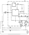
- the figure thus shows an example of the circuit S, P according to the invention, which contains a measuring arrangement T, R1 to R4, L1, L2, G1, G2.
- the circuit is e.g. from two units, namely the control unit P and the power supply unit S, which generates a stabilized operating voltage UA especially for the control unit P - and stabilized bias voltages for the test transistor T -.
- the circuit including its measuring arrangement is switched on via the switch Z - e.g. via the ignition lock of a motor vehicle - to its supply voltage, cf. the battery B.
- the measuring arrangement is used to test the ground connections E1, E2 of the circuit S, P.
- This circuit should be grounded in a highly reliable manner for the entire duration of the intended use of this circuit.
- the circuit represents e.g. B. represents a control circuit of an airbag system of a motor vehicle, which must be highly reliable during its entire intended service life.
- the circuit should check itself from time to time with the help of its measuring arrangement and even trigger an alarm if it detects that the grounding is still working at the moment, but that the grounding still has initial defects, i.e. the grounding of the Circuit should be repaired immediately or the entire circuit should be replaced.
- TWO ground connections E1, E2 which are to lead to the circuit point E with a low-resistance ground potential via TWO separated ground lines L1, L2.
- TWO separated ground lines L1, L2 TWO separated ground lines L1, L2.
- the circuit has a circuit point E to be grounded with two earth lines L1, L2 which are connected in parallel and which connect the circuit point E to the ground M.
- a separate measuring resistor is inserted in each of the two earth lines L1, L2, cf. G1 and G2. Accordingly, the invention has TWO groundings, although experts, as described above, always strive for "star grounding", that is, grounding via only one ground connection.
- the measuring resistor is in each of the two earth lines L1, L2, cf. G1 and G2, each formed by a diode.
- the measuring resistors - in particular the diodes G1, G2, which are polarized in the forward direction for the normal operating currents flowing to ground M - are all so low-impedance that these normal operating currents of the circuit S, P do not cause an excessive voltage drop UP or UC on them produce; In any case, the switching point E should be almost at ground potential.
- the potential at the circuit point is always determined by that of the two diodes G1 / G2, which has a potential at the ground connection E1 or E2 that comes closest to the potential of the ground M.
- the measuring arrangement at least occasionally checks the intactness of the ground connections E1, E2 of both earth lines L1, L2 by means of the voltages UP, UC.
- the measuring arrangement itself can temporarily generate these voltages for test purposes at the measuring resistors G1, G2, RL, RK during operation of the circuit or, if these voltages are present during operation, can observe them individually.
- the measuring arrangement should trigger an alarm in the event of a fault in one of the two groundings L1 / E1 or L2 / E2, namely, for example, switching on a buzzer or, for example, the warning light L, and / or, as it were, actuating any safety switch of any other circuit arrangement - depending on the purpose , to which the circuit according to the invention is used in each case.
- the housing G here is preferably metallically conductive and at the same time serves to shield the circuit from electromagnetic, capacitive and / or inductive interference. Because both earth connections E1, E2, which are attached to the housing G here - although insulated from each other - have practically no inherent resistance as long as they are intact, the operating currents of the circuit S, P - also possibly feed the test leads into the earth lines L1, L2 Current pulses representing test currents - no clear differences between the voltages UP and UC. However, if one of the two ground connections E1, E2 becomes more or less defective, then its inherent resistance increases, which may even become infinitely large.
- the control unit P which in this case also monitors the magnitude of the voltages UP and UC - can trigger the alarm.
- the measuring arrangement - in connection with the double grounding L1 / E1, L2 / E2 - triggers the alarm even if one of the two groundings L1 / E1 or L2 / E2 is faulty.
- the other of these two groundings then still works perfectly, so that the airbag continues to be triggered reliably in the event of an accident.
- the vehicle user is warned in good time by the invention to have the circuit - or more precisely: its grounding - repaired or to have the entire circuit replaced before the other grounding also becomes defective.
- the invention thus significantly reduces the dangers, above all caused by the aging of the circuit, for example caused by the vibrations in the motor vehicle.
- the ground connections E1, E2 can be arranged in the housing G close to one another.
- the earth lines L1, L2 can be attached to each other spatially close to each other for the same purpose, e.g. even more or less twisted together.
- the entire circuit including its measuring arrangement, but at least its earth lines L1, L2 and earth connections E1, E2 can be mounted in an earthed, conductive shielding housing G for the same purposes.
- the shielding housing G By means of such a shielding housing G one can even achieve a certain protection against electromagnetic, capacitive and inductive coupling of interference even if the earth lines L1, L2 should not be close together along their entire length - at least if the interference from outside, e.g. come from the ignition of the car engine. As far as such disturbances originate from parts of the circuit S, P, the shielding or encapsulation of the earth lines L1, L2, including their ground connections E1, E2, also provides appropriate protection.
- the measuring arrangement can contain a test transistor T, which from time to time emits current pulses via the earth lines L1, L2 for checking the ground connections E1, E2. Because, in the example shown, this current pulse - for example - is fed directly into the ground lines L1, L2 at the ground connections E1, E2, these current pulses generate strong differences between the voltages UP and UC, as a result of which the control unit P detects the defect from one of the two ground connections E1, E2 discovered immediately.
- Control circuits for airbags and other occupant protection systems must be constantly switched on while the vehicle is traveling; however, they should only emit a special output signal in an accident that triggers the occupant protection arrangement. The situation is similar with alarm systems.
- the test transistor T can transmit its current pulses to the actual circuit S , P past, feed directly into the earth lines L1, L2. It is then often advantageous, e.g. - the current paths through which the on the measuring resistors, cf. G1 and G2, occurring voltages, cf.
- the test transistor T to be largely decoupled from one another, to arrange the test transistor T so that it feeds its current pulses via a resistor network R2 / R1, R3 / R4 into the earth lines L1, L2, then the voltages MP, MC, the occur in the network R2 / R1, R3 / R4, can be used as indicators for the voltages UP, UC at the measuring resistors G1, G2, RL, RK.
- the test transistor T can feed its current pulses into the two earth lines L1, L2 simultaneously. However, it can also feed its current pulses in a clocked manner, namely first into the first earth line L1, later into the other earth line L2. Both methods are largely equivalent if the absolute values of both voltages UP and UC, or MP and MC, are measured - and possibly stored in the control unit P. If, on the other hand, only the difference between these voltages UP-UC or MP-MC is measured, it is easier to feed the current pulses into the two earth lines L1, L2 at the same time.
- resistors RL, RK as measuring resistors, which are already present outside the circuit in connection with the ground, especially if the circuit S, P is used as a control circuit of a motor vehicle occupant protection system, e.g. Airbag system and / or roll bar system, serves - the ground connections E1, E2 are connected to ground M via separate current paths RL, RK, at least one of these measuring resistors RL, RK e.g. as already mentioned, can be formed by the inherent resistance of a body section RK and / or a wiring harness line RL. As the figure shows by way of example, in the invention the ground connections, cf.
- the circuit point E can ground the entire circuit S, P centrally.
- the circuit can also contain a plurality of circuit points E which are separate from one another and to which the ground potential is to be introduced with as low an impedance as possible.
Landscapes
- Physics & Mathematics (AREA)
- General Physics & Mathematics (AREA)
- Engineering & Computer Science (AREA)
- Mechanical Engineering (AREA)
- Air Bags (AREA)
Claims (8)
- Circuit (S, P) comprenant un dispositif de mesure pour tester ses raccordements à la masse (E1, E2) pendant la totalité de la durée d'utilisation prévue de ce circuit (S, P), par exemple pour tester les raccordements à la masse du circuit de commande d'un système de coussin gonflable d'un véhicule automobile, un point de commutation (E) destiné à être mis à la terre, du circuit (S, P) étant relié par deux conducteurs de terre (L1, L2) à la masse (M),
caractérisé en ce que- chaque ligne de terre comporte au moins sa propre résistance de mesure (G1, G2, RL, RK), au moins une résistance de mesure de chaque conducteur de terre (L1, L2) étant constituée par une diode,- les résistances de mesure (G1, G2, RL, RK) destinées au courants de fonctionnement normaux, allant à la masse (M) du circuit (S, P), sont faiblement ohmiques, et- un dispositif de test est prévu, au moyen duquel les tensions (UP, UC) sur les résistances de mesure (G1, G2, RL, RK) sont contrôlées et tout défaut de la mise à la masse faisant l'objet d'une signalisation. - Circuit (S, P) selon la revendication 1, caractérisé en ce que- tant les raccordements de masse (E1, E2) entre eux qu'également les lignes de terre (L1, L2) entre elles sont respectivement placées près les uns des autres.
- Circuit (S, P) selon la revendication 1 ou 2, caractérisé en ce que,
les lignes de terre (L1, L2) sont raccordées entre le circuit (S, P) et un boîtier de blindage (G), conducteur, mis à la terre. - Circuit (S, P) selon l'une quelconque des revendications précédentes,
caractérisé en ce qu'- il comporte un transistor de contrôle (T), envoyant de temps en temps des impulsions électriques dans les lignes de terre (L1, L2), en vue de tester les raccordements de masse (E1, E2). - Circuit (S, P) selon la revendication 4, caractérisé en ce que- le transistor de contrôle (T) envoie ses impulsions électriques directement dans les lignes de terre (L1, L2) en dérivation sur le circuit (S, P) proprement dit.
- Circuit (S, P) selon la revendication 5, caractérisé en ce que- le transistor de contrôle (T) envoie ses impulsions électriques dans les lignes de terre (L1, L2) par un réseau de résistances (R2/R1, R3/R4), et- les tensions présentes (en MP, MC) dans le réseau ( R2/R1, R3/R4) sont utilisées comme indicateurs des tensions (UP, UC) sur les résistances de mesure (G1, G2, RL, RK).
- Circuit (S, P) selon l'une quelconque des revendications précédentes, servant de circuit de commande (S, P) d'un système de protection des passagers d'un véhicule automobile, par exemple d'un système à coussin gonflable et/ou d'un système d'arceau de sécurité, caractérisé en ce que- les raccordements de masse (E1, E2) sont reliés à la masse (M) par des chemins électriques (RL, RK) séparés, et- au moins l'une des résistances de mesure (G1, G2, RL, RK) est constitué par la résistance propre d'une section de carrosserie (RK) et/ou un conducteur d'un faisceau de fils (RL).
- Circuit (S, P) selon l'une quelconque des revendications précédentes,
caractérisé en ce que- le point de branchement (E) assure la mise à la terre centrale de tout le circuit (S, P).
Priority Applications (2)
| Application Number | Priority Date | Filing Date | Title |
|---|---|---|---|
| DE59205039T DE59205039D1 (de) | 1992-09-29 | 1992-09-29 | Messanordnung zur Prüfung der Masseanschlüsse einer Schaltung, z.B. Steuerschaltung eines Airbagsystemes eines Kfz |
| EP92116651A EP0590180B1 (fr) | 1992-09-29 | 1992-09-29 | Dispositif de mesure pour tester les connexions de masse d'une commande, par exemple commande d'un système d'airbag d'un véhicule |
Applications Claiming Priority (1)
| Application Number | Priority Date | Filing Date | Title |
|---|---|---|---|
| EP92116651A EP0590180B1 (fr) | 1992-09-29 | 1992-09-29 | Dispositif de mesure pour tester les connexions de masse d'une commande, par exemple commande d'un système d'airbag d'un véhicule |
Publications (2)
| Publication Number | Publication Date |
|---|---|
| EP0590180A1 EP0590180A1 (fr) | 1994-04-06 |
| EP0590180B1 true EP0590180B1 (fr) | 1996-01-10 |
Family
ID=8210072
Family Applications (1)
| Application Number | Title | Priority Date | Filing Date |
|---|---|---|---|
| EP92116651A Expired - Lifetime EP0590180B1 (fr) | 1992-09-29 | 1992-09-29 | Dispositif de mesure pour tester les connexions de masse d'une commande, par exemple commande d'un système d'airbag d'un véhicule |
Country Status (2)
| Country | Link |
|---|---|
| EP (1) | EP0590180B1 (fr) |
| DE (1) | DE59205039D1 (fr) |
Families Citing this family (9)
| Publication number | Priority date | Publication date | Assignee | Title |
|---|---|---|---|---|
| DE19619118C1 (de) * | 1996-05-11 | 1997-10-02 | Telefunken Microelectron | Verfahren zur Überprüfung der Funktionsfähigkeit eines Ausgangsschaltkreises einer Auslöseschaltung eines Sicherheitssystems |
| WO1999004277A1 (fr) * | 1997-07-17 | 1999-01-28 | Semtronics Corporation | Systeme de controle pour bande de poignet induisant une tension nulle |
| US6078875A (en) * | 1997-08-20 | 2000-06-20 | Semtronics Corporation | Automated auditing system |
| US6052053A (en) * | 1997-10-22 | 2000-04-18 | Semtronics Corporation | Continuous monitoring system |
| DE19836734C2 (de) * | 1998-08-13 | 2000-10-12 | Daimler Chrysler Ag | Verfahren zur Funktionsprüfung eines Zündkreises eines Insassenschutzsystems sowie Prüfschaltung |
| DE19932250A1 (de) * | 1999-07-10 | 2001-01-25 | Daimler Chrysler Ag | Verfahren zur Messung des ohmschen Widerstands einer elektrischen Verbindung und eines über diese elektrische Verbindung angeschlossenen Zünders einer Insassenschutzeinrichtung sowie einer Verbindung eines metallischen Gehäuseteils mit einem Massepotential |
| FR2904695A1 (fr) * | 2006-12-05 | 2008-02-08 | Siemens Vdo Automotive Sas | Procede et dispositif de prevention d'un defaut de liaison a la masse d'une unite de calcul a microprocesseur |
| FR3007530B1 (fr) * | 2013-06-20 | 2016-01-15 | Continental Automotive France | Dispositif de diagnostic de la perte d'une connexion entre un module de controle electronique et une masse |
| FR3011638B1 (fr) * | 2013-10-04 | 2017-05-26 | Continental Automotive France | Dispositif de diagnostic de la perte d'une connexion entre un module de controle electronique et une masse |
Family Cites Families (2)
| Publication number | Priority date | Publication date | Assignee | Title |
|---|---|---|---|---|
| US4366465A (en) * | 1981-10-02 | 1982-12-28 | Ford Motor Company | False failure detection prevention in an air bag diagnostic system |
| DE4032423A1 (de) * | 1990-10-12 | 1992-04-16 | Bosch Gmbh Robert | Elektronisches geraet |
-
1992
- 1992-09-29 DE DE59205039T patent/DE59205039D1/de not_active Expired - Fee Related
- 1992-09-29 EP EP92116651A patent/EP0590180B1/fr not_active Expired - Lifetime
Also Published As
| Publication number | Publication date |
|---|---|
| EP0590180A1 (fr) | 1994-04-06 |
| DE59205039D1 (de) | 1996-02-22 |
Similar Documents
| Publication | Publication Date | Title |
|---|---|---|
| DE3425281C2 (fr) | ||
| DE69115051T2 (de) | Verfahren und vorrichtung zum prüfen eines doppelten luftsack-passivrückhaltesystems. | |
| DE19913131B4 (de) | Stromversorgungssystem mit zwei Batterien unterschiedlicher Spannung | |
| DE4138096C2 (de) | Fehlererfassungseinrichtung für eine Automobilfahrgast-Schutzeinrichtung | |
| DE2140128B2 (de) | Steuerschaltung fuer das ausloesen einer aufblasbaren aufprallschutzvorrichtung fuer fahrzeuginsassen | |
| DE19520373B4 (de) | Fehlerdiagnosevorrichtung für eine Fahrgastschutzvorrichtung | |
| EP0410108A1 (fr) | Dispositif de commande pour un système de retenue dans des voitures | |
| DE68923220T2 (de) | Elektrische Auslösungsanordnung für eine Sicherheitseinrichtung in Kraftfahrzeugen. | |
| EP0590180B1 (fr) | Dispositif de mesure pour tester les connexions de masse d'une commande, par exemple commande d'un système d'airbag d'un véhicule | |
| DE4210861B4 (de) | Elektrischer Steuerschaltkreis für ein Insassen-Schutzsystem in Kraftfahrzeugen | |
| DE2447721B2 (de) | Überwachungsschaltung für ein Fahrzeug | |
| DE10020141B4 (de) | Bordnetzsystem | |
| DE102019109260B4 (de) | Verfahren zum Laden eines Fahrzeugs und Fahrzeug | |
| DE69211638T2 (de) | Einrichtung und verfahren zum testen eines rückhaltesystemes mit einem sicherheitsgassack (air-bag) mit zwei parallelen detektoren | |
| EP1114752B1 (fr) | Dispositif de surveillance de fil de batterie | |
| DE2308115A1 (de) | Stoerungsdetektor fuer eine sicherheitsvorrichtung bei fahrzeugen | |
| DE3886764T2 (de) | Auslösungsschaltkreis für einen airbag in fahrzeugen. | |
| DE102016224813A1 (de) | Kraftfahrzeug mit einem Elektromotor, insbesondere Hybrid- oder Elektrofahrzeug | |
| DE102012023460A1 (de) | Kraftfahrzeug-Bordnetz und Verfahren zum Erkennen eines Lichtbogens in einem Kraftfahrzeug-Bordnetz | |
| WO1991005680A1 (fr) | Circuit pour le declenchement d'un systeme de protection pour les occupants d'un vehicule | |
| DE2309113A1 (de) | Stoerungs-detektor fuer ein betaetigungsglied bei sicherheitsvorrichtungen in motorfahrzeugen | |
| DE2306307A1 (de) | Fehler-anzeigeanordnung bei einer fahrzeug-sicherheitsanordnung | |
| DE2701896C3 (de) | Fehlersuchgerät für elektrische Kreise | |
| DE102018221201B4 (de) | Kraftfahrzeug-Steuergerät mit mehreren Versorgungsanschlüssen für eine redundante Spannungsversorgung sowie Kraftfahrzeug mit dem Steuergerät und Verfahren zum Betreiben des Steuergeräts | |
| EP0732793A1 (fr) | Dispositif de circuit, spécialement pour systèmes critiques pour la sécurité dans des véhicules pour transport de personnes |
Legal Events
| Date | Code | Title | Description |
|---|---|---|---|
| PUAI | Public reference made under article 153(3) epc to a published international application that has entered the european phase |
Free format text: ORIGINAL CODE: 0009012 |
|
| AK | Designated contracting states |
Kind code of ref document: A1 Designated state(s): AT BE CH DE DK ES FR GB GR IE IT LI LU MC NL PT SE |
|
| RBV | Designated contracting states (corrected) |
Designated state(s): DE FR GB |
|
| 17P | Request for examination filed |
Effective date: 19940419 |
|
| 17Q | First examination report despatched |
Effective date: 19941229 |
|
| GRAA | (expected) grant |
Free format text: ORIGINAL CODE: 0009210 |
|
| AK | Designated contracting states |
Kind code of ref document: B1 Designated state(s): DE FR GB |
|
| REF | Corresponds to: |
Ref document number: 59205039 Country of ref document: DE Date of ref document: 19960222 |
|
| ET | Fr: translation filed | ||
| GBT | Gb: translation of ep patent filed (gb section 77(6)(a)/1977) |
Effective date: 19960322 |
|
| PGFP | Annual fee paid to national office [announced via postgrant information from national office to epo] |
Ref country code: GB Payment date: 19960821 Year of fee payment: 5 |
|
| PGFP | Annual fee paid to national office [announced via postgrant information from national office to epo] |
Ref country code: FR Payment date: 19960926 Year of fee payment: 5 |
|
| PLBE | No opposition filed within time limit |
Free format text: ORIGINAL CODE: 0009261 |
|
| PGFP | Annual fee paid to national office [announced via postgrant information from national office to epo] |
Ref country code: DE Payment date: 19961118 Year of fee payment: 5 |
|
| 26N | No opposition filed | ||
| PG25 | Lapsed in a contracting state [announced via postgrant information from national office to epo] |
Ref country code: GB Free format text: LAPSE BECAUSE OF NON-PAYMENT OF DUE FEES Effective date: 19970929 |
|
| PG25 | Lapsed in a contracting state [announced via postgrant information from national office to epo] |
Ref country code: FR Free format text: THE PATENT HAS BEEN ANNULLED BY A DECISION OF A NATIONAL AUTHORITY Effective date: 19970930 |
|
| GBPC | Gb: european patent ceased through non-payment of renewal fee |
Effective date: 19970929 |
|
| PG25 | Lapsed in a contracting state [announced via postgrant information from national office to epo] |
Ref country code: DE Free format text: LAPSE BECAUSE OF NON-PAYMENT OF DUE FEES Effective date: 19980603 |
|
| REG | Reference to a national code |
Ref country code: FR Ref legal event code: ST |