EP0590198A1 - Procédé et dispositif de surveillance du gaz d'un équipement blindé à haute tension - Google Patents
Procédé et dispositif de surveillance du gaz d'un équipement blindé à haute tension Download PDFInfo
- Publication number
- EP0590198A1 EP0590198A1 EP92116902A EP92116902A EP0590198A1 EP 0590198 A1 EP0590198 A1 EP 0590198A1 EP 92116902 A EP92116902 A EP 92116902A EP 92116902 A EP92116902 A EP 92116902A EP 0590198 A1 EP0590198 A1 EP 0590198A1
- Authority
- EP
- European Patent Office
- Prior art keywords
- gas
- pressure
- warning signal
- spaces
- signal
- Prior art date
- Legal status (The legal status is an assumption and is not a legal conclusion. Google has not performed a legal analysis and makes no representation as to the accuracy of the status listed.)
- Granted
Links
Images


Classifications
-
- H—ELECTRICITY
- H02—GENERATION; CONVERSION OR DISTRIBUTION OF ELECTRIC POWER
- H02B—BOARDS, SUBSTATIONS OR SWITCHING ARRANGEMENTS FOR THE SUPPLY OR DISTRIBUTION OF ELECTRIC POWER
- H02B13/00—Arrangement of switchgear in which switches are enclosed in, or structurally associated with, a casing, e.g. cubicle
- H02B13/02—Arrangement of switchgear in which switches are enclosed in, or structurally associated with, a casing, e.g. cubicle with metal casing
- H02B13/035—Gas-insulated switchgear
- H02B13/065—Means for detecting or reacting to mechanical or electrical defects
- H02B13/0655—Means for detecting or reacting to mechanical or electrical defects through monitoring changes of gas properties
Definitions
- the present invention relates to a method and a device for monitoring the gas of a compressed gas-insulated high-voltage device according to the preamble of claims 1 and 4, respectively.
- the heating of the gas in different gas spaces is usually not the same, even with the same current load.
- the resistance of switchgear is greater than that of busbars or parts thereof.
- not all system parts are always the same environmental influences, such as the same solar radiation or identical wind conditions exposed, which in turn affects the gas pressures in the individual gas spaces differently.
- a gas loss cannot be detected or can only be detected late.
- the gas space that is not critical with regard to gas loss and serves as a reference must be filled to the same gas density as the gas space to be monitored that is to be regarded as critical with regard to gas loss.
- this is not always desirable, since gas spaces assigned to circuit breakers, for example, often have to have a higher gas density than would be the case for the busbars.
- a device for monitoring the gas of a compressed gas-insulated high-voltage device is known from CH-A-651 970, which uses the density dependence of the breakdown voltage of a spark gap.
- a spark gap installed in the gas space to be monitored and constantly under voltage is set so that it ignites when the gas density falls below the minimum required.
- a relay is excited.
- This device is quite complex since a high-voltage transformer is required. If there is a temperature gradient in the gas space to be monitored and the spark gap is located at a location at a lower temperature, a gas loss may not be detected or may only be detected late.
- a gas monitoring relay is disclosed in CH-A-660 630, in which the density of the gas in the gas space to be monitored is determined from the signal of a pressure transmitter by temperature compensation by means of a bimetal.
- These monitoring relays are custom-made and therefore expensive to achieve the required accuracy is extremely difficult.
- the method according to the invention and the device according to the invention are provided for gas monitoring of multipole, pole-insulated high-voltage devices.
- isolated by poles means that each gas space that is closed in itself is assigned to a single pole.
- the difference in the gas pressures in corresponding gas spaces of different poles is determined. Due to their function, these gas spaces are always filled to the same gas density and are always placed close to each other so that they are exposed to the same environmental influences.
- these gas spaces have the same geometry and there in the multi-phase networks for im If essentially the same current load is provided in all phases, the heating by the current flow in the corresponding gas spaces is the same. A determined pressure difference between corresponding gas spaces of two poles is therefore due to a gas loss. This gives an extremely good sensitivity. In addition, the monitoring of high-voltage devices with only a single gas space per pole is made possible by the present invention.
- the reference numerals 10, 12 and 14 in FIGS. 1 to 4 denote gas spaces of a high-voltage device 16.
- these are the three gas compartments of a circuit breaker.
- a commercially available pressure transmitter 20 is attached to the encapsulation 18 of each gas space 10, 12, 14, which generates a digital or analog electrical signal dependent on gas pressure in the corresponding gas space 10, 12, 14 and via an electrical line 22 to only one outputs schematically indicated electronic circuit 24 of an evaluation device 25.
- This circuit 24 compares the signals from the three pressure sensors 20 with one another and emits a first warning signal W1 when the difference between the signals from two pressure sensors 20 exceeds a predetermined first limit value G1.
- This first limit value G1 corresponds to the highest permissible pressure difference in the gas spaces 10, 12, 14.
- the signals of the pressure sensors 20 are checked in the electronic circuit 24 to determine whether they do not fall below a likewise predetermined second limit value G2, for which purpose the signals of the pressure sensors 20 are preferably temperature-compensated. This can either be done by measuring the gas temperature in the gas spaces 10, 12, 14 and the electrical signals being corrected accordingly, for example in the electronic circuit 24, or by the pressure sensors 20 having temperature compensation. If the value falls below this second limit value G2, which corresponds to a minimum gas pressure, the electronic circuit 24 emits a second warning signal W2.
- a differential pressure switch 26 is connected between each two gas spaces 10, 12, 10, 14, 12, 14. These are connected via piping 28 to the corresponding gas spaces 10, 12, 14. Furthermore, a pressure switch 30 is connected to each gas space 10, 12, 14 via the piping 28.
- the differential pressure switch 26 and pressure switch 30 are also connected to an electronic circuit 24 via electrical lines 22.
- the differential pressure switches 26 are of a commercial type and emit a signal to the circuit 24 via the corresponding electrical lines 22 at least as soon as the pressure difference in the corresponding two gas spaces exceeds a predetermined first limit value G1. If such a signal is supplied to the electronic circuit 24 by at least one of the three differential pressure switches 26, the electronic circuit 24 generates a first warning signal W1. This warning signal W1 indicates a gas loss.
- the pressure switches 30 emit a signal to the circuit 24 via the corresponding electrical lines 22 as soon as the pressure in the corresponding gas space 10, 12, 14 falls below a predetermined limit value G2. These pressure switches 30 are preferably temperature compensated.
- the circuit 24 emits a second warning signal G2 as soon as one of the pressure switches 30 reports that the relevant second limit value G2 has been undershot.
- FIG. 3 corresponds essentially to that according to FIG. 1, but the pressure sensors 20 and the electronic circuit 24 are arranged in an on-site control cabinet 32 and the pressure sensors 20 are connected to the relevant gas space 10, 12, 14 via pipes 34 are.
- This form of training is particularly suitable for outdoor high-voltage devices in order to protect the pressure transmitter 20 and electronic circuit 24 against environmental influences.
- the differential pressure switches 26 and pressure switches 30 arranged in the on-site control cabinet 32 are connected to the gas spaces 10, 12, 14 and to one another with a piping 28 corresponding to FIG. 2.
- the circuit 24 is also arranged in the on-site control cabinet 32.
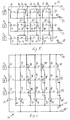
- multistage pressure switches 36 can be provided, as is indicated in FIGS. 5 and 6. These figures show the diagrams of two different designs of the electrical circuit 24 for evaluating the signals output by the multi-stage pressure switches 36.
- each multi-stage pressure switch 36 assigned to a gas space 10, 12, 14 has seven switch contacts designated 38.40.42.44.46.48.50, the switch contacts 38.40.44 and 48 is “opener” and the other switch contacts 42, 46 and 50 are "make contacts”.
- the switching contacts 38 to 50 assume the position shown in FIG. 5, ie the openers 38, 40, 44 and 48 are closed and the make contacts 42, 46.50 are open.
- the switch contact 38 opens.
- the switch contact 40 opens.
- the switch contact 42 closes and the switch contact 44 goes into its open position.
- the switching contact 46 closes and the opener 48 opens.
- the switching contact 50 closes.
- the switching contacts 38 of all pressure switches 36 are connected to one another and to an input line 52.
- a signal line 54, 56, 58 leads away from the switching contact 38 of each pressure switch 36.
- the other switching contacts 40, 44 and 48 which are also designed as openers, are connected on the one hand to the relevant signal line 54, 56, 58 and on the other hand each to a bridging conductor 60, 62, 64.
- These bridging conductors 60, 62, 64 connect the switching contacts 40, 44, 48 to one side of the switching contacts 42 or 46 or 50, which are designed as make contacts, the other side of which is connected to the input line 52.
- Continue the corresponding bridging conductors 60, 62, 64 are connected to one another by connecting lines 66, 66 ', 66''.
- the pressure in all three gas spaces 10, 12, 14 corresponds to a value that lies between the pressure values p4 and p5.
- the closers 50 are already open in all three multi-stage pressure switches 36 and the openers 48 are still in the open state. If the pressure in one of the gas spaces 10, 12, 14, for example in the gas space 12, falls below the pressure value p4, the opener 48 closes and the closer 46 opens in the relevant pressure switch 36.
- the signal line 56 remains separated from the input line 52, since the make contacts 50 are already open in all three pressure switches 36. The signal line 56 remains separated from the input line 52 until the pressure in the gas space 12 reaches the pressure value p3.
- the opener 44 closes, as a result of which the signal line 56 is connected to the input line 52 via this switch contact 44, the connecting line 66 'and the closed make 46 of the other two pressure switches 36, as a result of which the signal line 56 now indicates a pressure loss in the gas space 12.
- a warning signal W is generated in one or more of the Corresponding signal lines 54, 56, 58 are generated, but the pressure difference between two gas spaces 10, 12, 14 must always make up at least two stages of the multi-stage pressure switch 36. With the exception that a warning signal W is always issued if the pressure in one of the gas spaces 10, 12, 14 or in all of these gas spaces drops below the pressure value p1.
- each of the multi-stage pressure switches 36 assigned to one of the gas spaces 10, 12, 14 has switching contacts 70, 72, 74, 76, 80, 82 and 82 that function exclusively as "make contacts". If a minimum first pressure value p1 is reached with increasing pressure, the switching contact 70 closes. With a second pressure value p2 the switching contact 72 closes, with a third pressure value p3 the switching contacts 74 and 76 close, with the fourth pressure value p4 the switching contacts 78 and 80 bis when reached an uppermost pressure value p5 also closes the switching contact 82.
- all switching contacts 70, 72, 74, 76, 78, 80, 82 are open; on the other hand, if the pressure is equal to or greater than the pressure value p5, all switching contacts are closed.
- the switching contacts 70 of the three multi-stage pressure switches 36 and the excitation winding of a first relay 84 are connected in series between two input lines 86, 86 '. These input lines 86, 86 'are connected, for example, to the two poles of a DC voltage source.
- the switched contact 84 'of the first relay 84 is connected on the one hand to the input line 86 and on the other hand to a signal line 88.
- the switching contacts 72 and a second relay 90, the switching contacts 76 and a third relay 92 and the switching contacts 80 and a fourth relay 94 are connected in series between the two input lines 86, 86 '.
- the switching contacts 74 of the three multi-stage pressure switches 36 are connected in parallel, being connected on the input side to the input line 86 and on the output side via the switched contact 90 'of the second relay 90 to the signal line 88.
- the switching contacts 78 are connected between the input line 86 and the signal line 88 via the switched contact 92 'of the third relay 92 and the switching contacts 82 via the switched contacts 94' of the fourth relay 94.
- the switch contacts 80 open so that the fourth relay 94 drops out and closes the switched contact 94 '.
- the signal line 88 remains separated from the input line 86.
- the switching contacts 70 open, so that the first relay 84 is de-energized and the corresponding switched contact 84 'connects the signal line 88 to the input line 86 by closing, as a result of which the pressure loss is indicated on the signal line 88 (warning signal W).
- the pressure in all three gas spaces 10, 12, 14 is higher than the top pressure value p5. If, for example, the pressure in the gas space 14 drops to this pressure value p5, the switching contact 82 of the multi-stage pressure switch 36 assigned to the gas space 14 opens. This has no effect on the signal line 88 because all switching contacts 82 are connected in parallel. On the other hand, the pressure in the gas space 14 increases the pressure value p4, the corresponding switch contact 80 opens, so that the relay 94 drops out. This closes the switched contact 94 'and the signal line 88 connected to the input line 86 via this and the closed switching contacts 82 of the pressure switches 36 assigned to the gas spaces 10 and 12. The signal line 88 thus indicates a pressure loss (warning signal W). However, this signal does not show which gas space 10, 12, 14 has suffered a pressure loss. The difference of two or three switching stages of the pressure switches 36 thus defines the first limit value G1.
- the signal line 88 is separated from the input line 86, as described above. If the pressure now drops, for example in the gas space 10 below the pressure value p4, the switch contacts 78 and 80 of the corresponding multi-stage pressure switch 36 open, which has the consequence that the fourth relay 94 drops out and the switched contact 94 'closes. However, since the switch contacts 82 are already open, the signal line 88 remains separated from the input line 86. Only when the pressure drops to the pressure value p3 do the switch contacts 74 and 76 of the corresponding pressure switch 36 open, as a result of which the third relay 92 now drops and the switched contact 92 'is closed.
- the signal line 88 is connected to the input line 86 via the closed switching contacts 78 of the pressure switches 36 assigned to the gas spaces 12 and 14, which in turn generates a warning signal W indicating a pressure loss in the signal line 88.
- a signal is always generated in the signal line 88 based on each pressure when the pressure difference between two gas spaces 10, 12, 14 constitutes two switching stages of the multi-stage pressure switch 36, but always generates a warning signal W. is when the pressure in one or in all gas spaces 10, 12, 14 reaches the minimum pressure value p1.
Landscapes
- Engineering & Computer Science (AREA)
- Power Engineering (AREA)
- Gas-Insulated Switchgears (AREA)
- Driving Mechanisms And Operating Circuits Of Arc-Extinguishing High-Tension Switches (AREA)
Priority Applications (3)
| Application Number | Priority Date | Filing Date | Title |
|---|---|---|---|
| AT92116902T ATE130470T1 (de) | 1992-10-02 | 1992-10-02 | Verfahren und vorrichtung zur überwachung des gases einer druckgasisolierten hochspannungseinrichtung. |
| EP92116902A EP0590198B1 (fr) | 1992-10-02 | 1992-10-02 | Procédé et dispositif de surveillance du gaz d'un équipement blindé à haute tension |
| DE59204366T DE59204366D1 (de) | 1992-10-02 | 1992-10-02 | Verfahren und Vorrichtung zur Überwachung des Gases einer druckgasisolierten Hochspannungseinrichtung. |
Applications Claiming Priority (1)
| Application Number | Priority Date | Filing Date | Title |
|---|---|---|---|
| EP92116902A EP0590198B1 (fr) | 1992-10-02 | 1992-10-02 | Procédé et dispositif de surveillance du gaz d'un équipement blindé à haute tension |
Publications (2)
| Publication Number | Publication Date |
|---|---|
| EP0590198A1 true EP0590198A1 (fr) | 1994-04-06 |
| EP0590198B1 EP0590198B1 (fr) | 1995-11-15 |
Family
ID=8210095
Family Applications (1)
| Application Number | Title | Priority Date | Filing Date |
|---|---|---|---|
| EP92116902A Expired - Lifetime EP0590198B1 (fr) | 1992-10-02 | 1992-10-02 | Procédé et dispositif de surveillance du gaz d'un équipement blindé à haute tension |
Country Status (3)
| Country | Link |
|---|---|
| EP (1) | EP0590198B1 (fr) |
| AT (1) | ATE130470T1 (fr) |
| DE (1) | DE59204366D1 (fr) |
Citations (4)
| Publication number | Priority date | Publication date | Assignee | Title |
|---|---|---|---|---|
| DE1665637A1 (de) * | 1966-05-27 | 1971-03-25 | Siemens Ag | Druckgasisolierte Hochspannungsschaltanlage |
| DE2538314A1 (de) * | 1975-08-28 | 1977-03-10 | Bbc Brown Boveri & Cie | Anordnung zur ueberwachung und lokalisierung von gasverlusten in gekapselten, druckgasisolierten und geschotteten hochspannungsleitungen und hochspannungsschaltanlagen |
| EP0342597A2 (fr) * | 1988-05-16 | 1989-11-23 | Hitachi, Ltd. | Système d'abnormalité pour appareil à source de courant à haute tension |
| DE3910696A1 (de) * | 1989-04-03 | 1990-10-18 | Sachsenwerk Ag | Verfahren zum ueberwachen des drucks in einer druckgasgefuellten kammer sowie eine vorrichtung zur durchfuehrung des verfahrens |
-
1992
- 1992-10-02 EP EP92116902A patent/EP0590198B1/fr not_active Expired - Lifetime
- 1992-10-02 AT AT92116902T patent/ATE130470T1/de not_active IP Right Cessation
- 1992-10-02 DE DE59204366T patent/DE59204366D1/de not_active Expired - Fee Related
Patent Citations (4)
| Publication number | Priority date | Publication date | Assignee | Title |
|---|---|---|---|---|
| DE1665637A1 (de) * | 1966-05-27 | 1971-03-25 | Siemens Ag | Druckgasisolierte Hochspannungsschaltanlage |
| DE2538314A1 (de) * | 1975-08-28 | 1977-03-10 | Bbc Brown Boveri & Cie | Anordnung zur ueberwachung und lokalisierung von gasverlusten in gekapselten, druckgasisolierten und geschotteten hochspannungsleitungen und hochspannungsschaltanlagen |
| EP0342597A2 (fr) * | 1988-05-16 | 1989-11-23 | Hitachi, Ltd. | Système d'abnormalité pour appareil à source de courant à haute tension |
| DE3910696A1 (de) * | 1989-04-03 | 1990-10-18 | Sachsenwerk Ag | Verfahren zum ueberwachen des drucks in einer druckgasgefuellten kammer sowie eine vorrichtung zur durchfuehrung des verfahrens |
Non-Patent Citations (1)
| Title |
|---|
| PATENT ABSTRACTS OF JAPAN vol. 7, no. 290 (P-245)(1435) & JP-A-58 162 829 ( TOKYO SHIBAURA DENKI ) 27. September 1983 * |
Also Published As
| Publication number | Publication date |
|---|---|
| DE59204366D1 (de) | 1995-12-21 |
| EP0590198B1 (fr) | 1995-11-15 |
| ATE130470T1 (de) | 1995-12-15 |
Similar Documents
| Publication | Publication Date | Title |
|---|---|---|
| EP1380042B1 (fr) | Unite de distribution, notamment demarreur de moteur, pour un consommateur | |
| DE102014102373B3 (de) | Netzknoten für ein Stromnetz, Regeltransformator für einen Netzknoten und Verfahren zum Betreiben eines Netzknotens | |
| DE102007017543B4 (de) | Verfahren zur Entfernungsortung von Erdschlüssen | |
| DE19832535C2 (de) | Einrichtung zur Regelung und Überwachung von Weichenheizungen | |
| EP2555003B1 (fr) | Transducteur de courant et sectionneur de charge étant équipé avec celui-ci | |
| WO2023052041A1 (fr) | Disjoncteur et procédé | |
| EP3262664B1 (fr) | Procédé permettant de modifier le nombre de spires actives d'un enroulement de régulation dans une installation électrique et installation électrique munie d'un enroulement de régulation | |
| EP3278349B1 (fr) | Ensemble d'armoire électrique avec mise hors circuit améliorée en cas de surcharge | |
| EP0590198B1 (fr) | Procédé et dispositif de surveillance du gaz d'un équipement blindé à haute tension | |
| EP3143417B1 (fr) | Procédé et système permettant de vérifier une installation de distribution destinée à une installation de transmission d'énergie | |
| WO2023088746A1 (fr) | Procédé et dispositif pour déterminer l'état d'un commutateur | |
| DE102007019021A1 (de) | Leistungsschütz, insbesondere Vakuumschütz | |
| DE102005022060A1 (de) | Überwachungssystem zur Überwachung wenigstens eines kritischen Bereichs einer Anlage der elektrischen Energieversorgung | |
| EP4416473B1 (fr) | Procédé d'utilisation d'un appareillage de commutation et appareillage de commutation | |
| EP1285282A1 (fr) | Procede et dispositif permettant de detecter des arcs electriques accidentels | |
| EP0827251B1 (fr) | Interrupteur électrique à basse tension | |
| EP4416472B1 (fr) | Procédé de fonctionnement d'un appareillage de commutation et appareillage de commutation | |
| WO2022207159A1 (fr) | Surveillance de l'opérabilité d'un commutateur haute tension | |
| DE3828015A1 (de) | Verfahren zur ueberwachung des isoliergases von druckgasisolierten schaltanlagen und steuereinrichtung zur durchfuehrung dieses verfahrens | |
| EP0508177B1 (fr) | Relais de protection digital | |
| DE10029106B4 (de) | Verfahren zur Steuerung und entsprechende Schaltungsanordnung | |
| DE3910696A1 (de) | Verfahren zum ueberwachen des drucks in einer druckgasgefuellten kammer sowie eine vorrichtung zur durchfuehrung des verfahrens | |
| DE202014001799U1 (de) | Trafostufenschalter | |
| DE3038561A1 (de) | Hochspanungsschalter mit mindestens zwei unterschiedlich beschalteten schaltstrecken | |
| EP0991159B1 (fr) | Appareil de détection des défauts de phase |
Legal Events
| Date | Code | Title | Description |
|---|---|---|---|
| PUAI | Public reference made under article 153(3) epc to a published international application that has entered the european phase |
Free format text: ORIGINAL CODE: 0009012 |
|
| AK | Designated contracting states |
Kind code of ref document: A1 Designated state(s): AT BE CH DE DK ES FR GB GR IE IT LI LU MC NL PT SE |
|
| RAP1 | Party data changed (applicant data changed or rights of an application transferred) |
Owner name: GEC ALSTHOM T&D AG |
|
| RBV | Designated contracting states (corrected) |
Designated state(s): AT CH DE LI |
|
| 17P | Request for examination filed |
Effective date: 19940929 |
|
| 17Q | First examination report despatched |
Effective date: 19950419 |
|
| GRAA | (expected) grant |
Free format text: ORIGINAL CODE: 0009210 |
|
| AK | Designated contracting states |
Kind code of ref document: B1 Designated state(s): AT CH DE LI |
|
| REF | Corresponds to: |
Ref document number: 130470 Country of ref document: AT Date of ref document: 19951215 Kind code of ref document: T |
|
| REF | Corresponds to: |
Ref document number: 59204366 Country of ref document: DE Date of ref document: 19951221 |
|
| PLBE | No opposition filed within time limit |
Free format text: ORIGINAL CODE: 0009261 |
|
| 26N | No opposition filed | ||
| REG | Reference to a national code |
Ref country code: CH Ref legal event code: PFA Free format text: GEC ALSTHOM T&D AG TRANSFER- GEC ALSTHOM AG * GEC ALSTHOM AG TRANSFER- ALSTOM AG |
|
| PGFP | Annual fee paid to national office [announced via postgrant information from national office to epo] |
Ref country code: CH Payment date: 20000921 Year of fee payment: 9 |
|
| PGFP | Annual fee paid to national office [announced via postgrant information from national office to epo] |
Ref country code: AT Payment date: 20000926 Year of fee payment: 9 |
|
| PGFP | Annual fee paid to national office [announced via postgrant information from national office to epo] |
Ref country code: DE Payment date: 20001005 Year of fee payment: 9 |
|
| PG25 | Lapsed in a contracting state [announced via postgrant information from national office to epo] |
Ref country code: AT Free format text: LAPSE BECAUSE OF NON-PAYMENT OF DUE FEES Effective date: 20011002 |
|
| PG25 | Lapsed in a contracting state [announced via postgrant information from national office to epo] |
Ref country code: LI Free format text: LAPSE BECAUSE OF NON-PAYMENT OF DUE FEES Effective date: 20011031 Ref country code: CH Free format text: LAPSE BECAUSE OF NON-PAYMENT OF DUE FEES Effective date: 20011031 |
|
| REG | Reference to a national code |
Ref country code: CH Ref legal event code: PL |
|
| PG25 | Lapsed in a contracting state [announced via postgrant information from national office to epo] |
Ref country code: DE Free format text: LAPSE BECAUSE OF NON-PAYMENT OF DUE FEES Effective date: 20020702 |