EP0590217A1 - Verfahren und Vorrichtung zum Vorbereiten von einer Folie aus flexiblem Material zur Verpackung eines Paketes, insbesondere eines Paketes für Tabakindustriewaren - Google Patents
Verfahren und Vorrichtung zum Vorbereiten von einer Folie aus flexiblem Material zur Verpackung eines Paketes, insbesondere eines Paketes für Tabakindustriewaren Download PDFInfo
- Publication number
- EP0590217A1 EP0590217A1 EP92810739A EP92810739A EP0590217A1 EP 0590217 A1 EP0590217 A1 EP 0590217A1 EP 92810739 A EP92810739 A EP 92810739A EP 92810739 A EP92810739 A EP 92810739A EP 0590217 A1 EP0590217 A1 EP 0590217A1
- Authority
- EP
- European Patent Office
- Prior art keywords
- strip
- sheet
- movement
- precut
- blade
- Prior art date
- Legal status (The legal status is an assumption and is not a legal conclusion. Google has not performed a legal analysis and makes no representation as to the accuracy of the status listed.)
- Withdrawn
Links
Images

Classifications
-
- B—PERFORMING OPERATIONS; TRANSPORTING
- B26—HAND CUTTING TOOLS; CUTTING; SEVERING
- B26F—PERFORATING; PUNCHING; CUTTING-OUT; STAMPING-OUT; SEVERING BY MEANS OTHER THAN CUTTING
- B26F3/00—Severing by means other than cutting; Apparatus therefor
- B26F3/002—Precutting and tensioning or breaking
-
- B—PERFORMING OPERATIONS; TRANSPORTING
- B65—CONVEYING; PACKING; STORING; HANDLING THIN OR FILAMENTARY MATERIAL
- B65B—MACHINES, APPARATUS OR DEVICES FOR, OR METHODS OF, PACKAGING ARTICLES OR MATERIALS; UNPACKING
- B65B19/00—Packaging rod-shaped or tubular articles susceptible to damage by abrasion or pressure, e.g. cigarettes, cigars, macaroni, spaghetti, drinking straws or welding electrodes
- B65B19/02—Packaging cigarettes
- B65B19/22—Wrapping the cigarettes; Packaging the cigarettes in containers formed by folding wrapping material around formers
- B65B19/228—Preparing and feeding blanks
-
- B—PERFORMING OPERATIONS; TRANSPORTING
- B65—CONVEYING; PACKING; STORING; HANDLING THIN OR FILAMENTARY MATERIAL
- B65B—MACHINES, APPARATUS OR DEVICES FOR, OR METHODS OF, PACKAGING ARTICLES OR MATERIALS; UNPACKING
- B65B61/00—Auxiliary devices, not otherwise provided for, for operating on sheets, blanks, webs, binding material, containers or packages
- B65B61/04—Auxiliary devices, not otherwise provided for, for operating on sheets, blanks, webs, binding material, containers or packages for severing webs, or for separating joined packages
- B65B61/12—Auxiliary devices, not otherwise provided for, for operating on sheets, blanks, webs, binding material, containers or packages for severing webs, or for separating joined packages by tearing along perforations or lines of weakness
Definitions
- the present invention relates to a process for preparing a sheet of flexible material, such as a polypropylene or cellophane sheet, intended for the packaging of a package, said sheet being cut from a strip animated by a movement of longitudinal displacement, the appropriate device using this method and a packaging machine equipped with such a device.
- the invention applies particularly, but not exclusively, to the packaging of packets of tobacco industry products such as cigarettes, cigars or cigarillos.
- preparation of a packaging sheet is meant cutting it to the necessary dimensions as well as presenting it on the package it is to package, this by automatic processes.
- US-A-4,151,699 describes a device by which the packaging sheet is cut in two stages, firstly a cutting of the two portions close to the edge of the strip, followed by cutting of its part central.
- This device requires a complex synchronization of the two knives so that the two cuts are connected; proof of the difficulty of this operation is provided by the fact that small longitudinal cuts are necessary at the points of connection of the cuts.
- Patent US-A-4,388,794 is an improvement on the previous one; in this case the side edges of the cutting sheet are driven by two belts endless, the running speed of said belts being slightly higher than that of the strip and the two belts going away slightly from one another in order to tension the cut sheet. Since the cuts are made in the same manner as above, the drawbacks mentioned remain.
- Patent EP-B-0.109.582 shows a device on which the sheet to be cut is driven successively by two side bands, then by a roller where it is cut, before ironing on two side bands, thereby following a fairly path complicated.
- a first object of the invention is therefore to propose a process for preparing a packaging sheet by which the drawbacks mentioned above are avoided; this first object being obtained by a process, certain steps of which are described in claim 1.
- Another object of the invention is to propose an adequate device making it possible to carry out the above method, capable of operating at high speed without risk of jamming and the synchronization of the various functions of which is simplified. This goal is achieved by a device as described in claims 2 to 8.
- Yet another object of the invention is to provide a packaging machine, which can be equipped with the device, as described above, originally or later, this packaging machine being in accordance with claim 9.
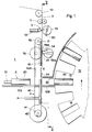
- FIG. 1 represents a partial side view of the device
- FIG. 2 represents a front view of the device according to line II-II of FIG. 1
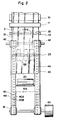
- Figure 3 shows schematically the control of the cutting blade and the tear blade of the device.
- each packet 20 must be covered with a protective sheet 30.
- These protective sheets 30, generally made of polypropylene or cellophane, are cut from a continuous strip 3, unwound from a reel (not shown), said strip 3 being guided by one or more guide rollers 10 and driven at constant linear speed by one or more drive rollers 11 to be presented, preferably vertically in a movement from top to bottom, directly to the - above the cutting device.
- This is firstly composed of drive means 4 for the strip 3, respectively of a precut sheet 31, preferably consisting of two endless belts 40, arranged in parallel spaced apart, the space between the two belts being slightly greater than the width of a bundle, a strand of each of them moving linearly parallel and at a very small distance from part of the path of the strip 3, the lateral edges of the strip 3, respectively of the precut sheet 31 superimposed on said strands.
- the two belts 40 each circulate around at least two deflection rollers 41,42, one deflection roller at least of each of the two belts, for example the rollers 41, being driven in rotation by drive means 43 , so that the linear speed of the strand of the belts 40 being circulated parallel to the strip 3 is very slightly greater than the constant linear speed of the said strip, for reasons which will be explained later.
- Each of the belts 40 is provided with a plurality of orifices 44 (see FIG. 2) connecting a vacuum chamber 45, one outlet of which is connected to a suction installation, not shown.
- the notched part of the belts 40 comprises a longitudinal guide groove 40B (see FIG. 2) which corresponds to a rib longitudinal arranged on the bearing face of the vacuum chamber 45. In this way, the longitudinal speed guide as well as the lateral guide in position of the strip 3 as well as of the precut sheet 31 are perfectly ensured.
- the device further comprises cutting means 5, preferably composed of a cutting blade 50 mounted on a pivoting cylinder 51 and a fixed counter blade 52, mounted exactly opposite the cutting position of the blade 50, the other side of the strip 3.
- the cutting means 5 are installed on a portion of rectilinear path of the strip 3, between the last drive rollers 11 and the top of the belts 40.
- the cutting blade 50 of the device according to the he invention is particular in that, as seen in Figure 3, its cutting edge is not continuous but has a plurality of notches 50A.
- the pivoting cylinder 51 is rotated by drive means 53, synchronized so that the cut 32 (see Figure 2) takes place at the appropriate place on the strip 3 so as to pre-cut sheets 31 of length determined.
- FIG. 2 The action of the blade 50 on the strip 3 is also visible in FIG. 2 where it can be seen that the cutout 32 is not continuous but has attachment points 32A corresponding to each of the notches 50A.
- the precut sheet 31 is not immediately completely separated from the strip 3, but remains attached to the latter by the attachment points 32A.
- the strip 3 as well as the precut sheet 31, held by the attachment points 32A always move at the linear speed of the strip 3, ie at a speed slightly lower than that of the belts 40; therefore a slight sliding occurs between the portions of the precut sheet 31 and the portions of belts 40 in contact. This sliding is possible given the low value of the vacuum imposed by the vacuum chamber 45.
- the number of attachment points 32A and their width are determined taking into account the thickness of the tape 3, its mechanical strength, etc.
- the strip 3 can also comprise a continuous tear tape placed longitudinally on the said strip, the cutting blade 50 leaving an uncut space on either side of the said tape, which a second cutting blade subsequently cuts in a slightly offset position. compared to the first cut.
- This portion of the device for including a tear tape from the packaging is well known in the art, it is therefore not shown in the figures but can easily be integrated into the device according to the invention.
- a tear blade 54 strikes the precut sheet 31 on an area 33 in an approximately tangential movement in the direction of movement of the precut sheet 31.
- the cutting blade stripping 54 is arranged on one side of a lower portion of the precut sheet 31, opposite which, on the other side of the precut sheet 31 and in contact with the latter by a generator, there are a support surface, preferably one or more support rollers 55 in free rotation about an axis parallel to the plane of the precut sheet 31 but perpendicular to its direction of movement.
- the tear blade 54 has the general shape of a rectangular parallelepiped, its face 54A which strikes the precut sheet 31 being convex.
- the blade 54 pivots about an axis parallel to that of the support roller (s) 55, it is driven in rotation around this axis by drive means 56 comprising movement acceleration means 56A such as for example a box comprising elliptical gears, in such a way that an acceleration of the rotation movement of the blade 54 is applied to it just before the face 54A of the said blade strikes the zone 33 of the precut sheet 31, the roll or rolls support 55 having the role of a counter-support.
- movement acceleration means 56A such as for example a box comprising elliptical gears
- the sheet 34 is therefore now completely separated from the strip 3, the acceleration movement which has been printed has enabled it to reach the speed of movement of the belts 40 which move, as indicated above, at a speed slightly higher than that of the strip 3 and to be driven by the belts 40, being held by suction against them.
- a space has therefore been created between the lower edge of the ribbon 3 and the upper edge of the precut sheet 31, these two edges can no longer come into contact and / or overlap, thereby avoiding the risk of causing the machine to jam.
- the means for driving in rotation 53 of the cutting blade 50 as well as the means for driving in rotation 56 of the tearing blade 54 are synchronized with one another and with the means for driving in rotation 43 of the belts 40 by a synchronization device 57 of known technique.
- the synchronization device 57 can be of relatively simple design since it is not necessary for the tear blade 54 to strike the precut sheet in a precise location, the zone 33 possibly being located anywhere along the length of the precut sheet 31, the only condition being that the lower end of the strip 3 which immediately follows the precut sheet 31 to be torn off is already engaged and driven by the belts 40.
- the tear blade 54 Since we are seeking to obtain a device of dimensions as small as possible, the tear blade 54 will be disposed at a relatively small distance from the top of the belts 40, respectively of the rollers 42; therefore, the zone 33 is preferably in a position fairly close to the precut 32.
- Figure 1 seems to show that it is possible to have a precut sheet 31 and a cut sheet 34 arranged one after the other simultaneously on the belts 40. In fact, and if the device is of reduced dimensions as has just been said, we could not have such a provision; the pins 31 and 34 in Figure 1 are only used to mount approximately the positions taken by the sheets 31 or 34 on the device. If the device is longer than shown, in particular if the belts 40 are longer, it would then be possible to have several sheets 31 and / or 34 transported simultaneously by the drive means 4.
- the width of the slide 12A is slightly less than the space between the two belts 40 (see FIG. 2), and its front end comes just flush with the plane on which the cut sheet 34 moves.
- the synchronization device 57 controls the lever or the piston 13, by means of actuation means 14, so that the packet 20 is propelled towards the sheet cut 34 and continuing to slide on the slide 12B, drives said sheet until it goes to be housed in a housing 15 arranged in a receiving wheel 16 of known technique.
- the receiving wheel 16 continues its sequential rotational movement as indicated by the arrow, the upper portions of the packaging sheet 30 will be folded down and sealed on the package in order to completely close it to make it waterproof, by a technical device. known.
- the knife 50 carrying out the precut 32 it is not absolutely necessary for the knife 50 carrying out the precut 32 to be driven by a rotary movement; a similar result can be obtained with a knife making a movement perpendicular to that of the strip 3.
- the counter blade 52 does not absolutely have to be fixed, it can also be a bearing surface or a 'a roll, can also possibly be provided with notches corresponding to the notches 52A of the cutting blade.
- the acceleration of the tear blade 54 can also be caused by other means than those described, for example by a cam or by a piston.
- the method and the device described meet the set goals, that is to allow the presentation of packaging sheets without risk of jamming and at high rate of operation.
- a device as described can be originally mounted on a packaging machine or can be later mounted to improve it.
Landscapes
- Engineering & Computer Science (AREA)
- Mechanical Engineering (AREA)
- Life Sciences & Earth Sciences (AREA)
- Forests & Forestry (AREA)
- Auxiliary Devices For And Details Of Packaging Control (AREA)
- Wrapping Of Specific Fragile Articles (AREA)
Priority Applications (3)
| Application Number | Priority Date | Filing Date | Title |
|---|---|---|---|
| EP92810739A EP0590217A1 (de) | 1992-10-01 | 1992-10-01 | Verfahren und Vorrichtung zum Vorbereiten von einer Folie aus flexiblem Material zur Verpackung eines Paketes, insbesondere eines Paketes für Tabakindustriewaren |
| EP19930810644 EP0591101B1 (de) | 1992-10-01 | 1993-09-10 | Verfahren und Vorrichtung zum Vorbereiten von einer Folie aus flexibelem Material zur Verpackung eines Paketes, insbesondere eines Paketes für Tabakindustriewaren |
| DE1993601078 DE69301078T2 (de) | 1992-10-01 | 1993-09-10 | Verfahren und Vorrichtung zum Vorbereiten von einer Folie aus flexibelem Material zur Verpackung eines Paketes, insbesondere eines Paketes für Tabakindustriewaren |
Applications Claiming Priority (1)
| Application Number | Priority Date | Filing Date | Title |
|---|---|---|---|
| EP92810739A EP0590217A1 (de) | 1992-10-01 | 1992-10-01 | Verfahren und Vorrichtung zum Vorbereiten von einer Folie aus flexiblem Material zur Verpackung eines Paketes, insbesondere eines Paketes für Tabakindustriewaren |
Publications (1)
| Publication Number | Publication Date |
|---|---|
| EP0590217A1 true EP0590217A1 (de) | 1994-04-06 |
Family
ID=8211998
Family Applications (1)
| Application Number | Title | Priority Date | Filing Date |
|---|---|---|---|
| EP92810739A Withdrawn EP0590217A1 (de) | 1992-10-01 | 1992-10-01 | Verfahren und Vorrichtung zum Vorbereiten von einer Folie aus flexiblem Material zur Verpackung eines Paketes, insbesondere eines Paketes für Tabakindustriewaren |
Country Status (2)
| Country | Link |
|---|---|
| EP (1) | EP0590217A1 (de) |
| DE (1) | DE69301078T2 (de) |
Cited By (3)
| Publication number | Priority date | Publication date | Assignee | Title |
|---|---|---|---|---|
| WO1998000336A3 (en) * | 1996-06-28 | 1998-03-12 | Douglas Machine Ltd Liability | Apparatus and methods for producing shrink wrap packaging |
| US7032360B2 (en) | 2003-10-29 | 2006-04-25 | Douglas Machine, Inc. | Apparatus and methods for producing shrink wrap packaging |
| CN112278359A (zh) * | 2020-11-04 | 2021-01-29 | 上海烟草机械有限责任公司 | 一种烟组与内衬纸并行输送装置 |
Citations (5)
| Publication number | Priority date | Publication date | Assignee | Title |
|---|---|---|---|---|
| DE431290C (de) * | 1923-07-07 | 1926-07-06 | Johannes Bergmann Knobel | Abreissvorrichtung fuer Cellulose- und andere Bahnen |
| US1772785A (en) * | 1925-10-26 | 1930-08-12 | Hoague Sprague Corp | Art of working cardboard and similar material |
| US4388794A (en) * | 1975-07-11 | 1983-06-21 | Focke & Pfuhl | Apparatus for cutting and transporting blanks from a web of flexible material |
| EP0187323A1 (de) * | 1985-01-10 | 1986-07-16 | Focke & Co. (GmbH & Co.) | Verfahren und Vorrichtung zum Herstellen von Zuschnitten für Verpackungen |
| US5076555A (en) * | 1990-07-25 | 1991-12-31 | Bunch Jr Earnest B | Apparatus for partially severing strip of paper along lines offset from lines of weakening in the paper |
-
1992
- 1992-10-01 EP EP92810739A patent/EP0590217A1/de not_active Withdrawn
-
1993
- 1993-09-10 DE DE1993601078 patent/DE69301078T2/de not_active Expired - Fee Related
Patent Citations (5)
| Publication number | Priority date | Publication date | Assignee | Title |
|---|---|---|---|---|
| DE431290C (de) * | 1923-07-07 | 1926-07-06 | Johannes Bergmann Knobel | Abreissvorrichtung fuer Cellulose- und andere Bahnen |
| US1772785A (en) * | 1925-10-26 | 1930-08-12 | Hoague Sprague Corp | Art of working cardboard and similar material |
| US4388794A (en) * | 1975-07-11 | 1983-06-21 | Focke & Pfuhl | Apparatus for cutting and transporting blanks from a web of flexible material |
| EP0187323A1 (de) * | 1985-01-10 | 1986-07-16 | Focke & Co. (GmbH & Co.) | Verfahren und Vorrichtung zum Herstellen von Zuschnitten für Verpackungen |
| US5076555A (en) * | 1990-07-25 | 1991-12-31 | Bunch Jr Earnest B | Apparatus for partially severing strip of paper along lines offset from lines of weakening in the paper |
Cited By (4)
| Publication number | Priority date | Publication date | Assignee | Title |
|---|---|---|---|---|
| WO1998000336A3 (en) * | 1996-06-28 | 1998-03-12 | Douglas Machine Ltd Liability | Apparatus and methods for producing shrink wrap packaging |
| US5771662A (en) * | 1996-06-28 | 1998-06-30 | Douglas Machine Limited Liability Company | Apparatus and methods for producing shrink wrap packaging |
| US7032360B2 (en) | 2003-10-29 | 2006-04-25 | Douglas Machine, Inc. | Apparatus and methods for producing shrink wrap packaging |
| CN112278359A (zh) * | 2020-11-04 | 2021-01-29 | 上海烟草机械有限责任公司 | 一种烟组与内衬纸并行输送装置 |
Also Published As
| Publication number | Publication date |
|---|---|
| DE69301078T2 (de) | 1996-07-25 |
| DE69301078D1 (de) | 1996-02-01 |
Similar Documents
| Publication | Publication Date | Title |
|---|---|---|
| EP1003635B1 (de) | Verfahren und gerät zur sequentiellen vorbereitung von verpackungszuschnitten, und zigarettenschachtel | |
| EP0086153B1 (de) | Maschine zum Falten von Platten | |
| EP0693424B1 (de) | Verfahren und Vorrichtung zur Herstellung von Verpackungszuschnitten | |
| EP0960831A1 (de) | Mit einem Coupon versehene Verpackung sowie Verfahren zur Herstellung dieser Verpackung | |
| CH621530A5 (de) | ||
| EP0514340B1 (de) | Verfahren und Vorrichtung zum Vorbereiten von Verpackungszuschnitten | |
| FR2655947A1 (fr) | Dispositif pour l'application de bandes a des paquets sensiblement parallelepipediques. | |
| EP0251833B1 (de) | Einrichtung zur zeitweisen Einlagerung von flachen Gegenständen | |
| EP0000851A1 (de) | Automatische Vorrichtung zum Zerteilen eines thermoplastischen Schlauches und zum Überziehen von Behältern mittels dieser Schlauchteilen | |
| FR2484979A1 (fr) | Procede et appareil d'assemblage de matiere en feuille, notamment pour alimenter en continu des imprimantes rapides | |
| EP0394707B1 (de) | Vorrichtung zum nacheinander Zuführen von Platten zu einer Verarbeitungsmaschine | |
| EP0590217A1 (de) | Verfahren und Vorrichtung zum Vorbereiten von einer Folie aus flexiblem Material zur Verpackung eines Paketes, insbesondere eines Paketes für Tabakindustriewaren | |
| EP0591101B1 (de) | Verfahren und Vorrichtung zum Vorbereiten von einer Folie aus flexibelem Material zur Verpackung eines Paketes, insbesondere eines Paketes für Tabakindustriewaren | |
| EP0662437B1 (de) | Vorrichtung zum Verbinden von Bändern aus weichem Material | |
| CA1314020C (fr) | Dispositif pour envelopper des produits dans des etuis avec etiquette | |
| EP2613943B1 (de) | Verfahren für die zuführung von zu prägenden streifen in einem system zu ihrer bewegung sowie vorrichtung zur umsetzung dieses verfahrens | |
| FR2518496A1 (fr) | Dispositif pour l'alimentation en etiquettes et vignettes analogues | |
| EP0004631B1 (de) | Verpackungsvorrichtung und -verfahren | |
| FR2754240A1 (fr) | Dispositif d'application de bandes de dechirement | |
| EP0900737A1 (de) | Vorrichtung zum Aufbringen und Perforieren eines biegsamen Versteifungs- und/oder Führungsbandes, Verfahren und auf diese Weise hergestellter Verpackungsbehälter | |
| CH621531A5 (en) | Device for continuously and automatically opening signatures intended to be assembled in order to form a book | |
| CH633490A5 (fr) | Dispositif de separation de billets de banque. | |
| FR2867750A1 (fr) | Machine et bobine pour tear and tip | |
| EP0913330A1 (de) | Vorrichtung zum Anbringen eines Schnittes in die Umhüllung einer vorbeilaufenden Last | |
| BE843548A (fr) | Procede pour la fabrication de sacs empiles sur des fourches de transport et machine pour la mise en oeuvre de ce procede |
Legal Events
| Date | Code | Title | Description |
|---|---|---|---|
| PUAI | Public reference made under article 153(3) epc to a published international application that has entered the european phase |
Free format text: ORIGINAL CODE: 0009012 |
|
| AK | Designated contracting states |
Kind code of ref document: A1 Designated state(s): CH LI |
|
| 18D | Application deemed to be withdrawn |
Effective date: 19941007 |