EP0590249A2 - Couverture pour marquise - Google Patents
Couverture pour marquise Download PDFInfo
- Publication number
- EP0590249A2 EP0590249A2 EP93110971A EP93110971A EP0590249A2 EP 0590249 A2 EP0590249 A2 EP 0590249A2 EP 93110971 A EP93110971 A EP 93110971A EP 93110971 A EP93110971 A EP 93110971A EP 0590249 A2 EP0590249 A2 EP 0590249A2
- Authority
- EP
- European Patent Office
- Prior art keywords
- cover
- awning
- slot
- tongue
- profile rib
- Prior art date
- Legal status (The legal status is an assumption and is not a legal conclusion. Google has not performed a legal analysis and makes no representation as to the accuracy of the status listed.)
- Withdrawn
Links
Images


Classifications
-
- E—FIXED CONSTRUCTIONS
- E04—BUILDING
- E04F—FINISHING WORK ON BUILDINGS, e.g. STAIRS, FLOORS
- E04F10/00—Sunshades, e.g. Florentine blinds or jalousies; Outside screens; Awnings or baldachins
- E04F10/02—Sunshades, e.g. Florentine blinds or jalousies; Outside screens; Awnings or baldachins of flexible canopy materials, e.g. canvas ; Baldachins
- E04F10/06—Sunshades, e.g. Florentine blinds or jalousies; Outside screens; Awnings or baldachins of flexible canopy materials, e.g. canvas ; Baldachins comprising a roller-blind with means for holding the end away from a building
- E04F10/0662—Sunshades, e.g. Florentine blinds or jalousies; Outside screens; Awnings or baldachins of flexible canopy materials, e.g. canvas ; Baldachins comprising a roller-blind with means for holding the end away from a building with arrangements for fastening the blind to the building
-
- E—FIXED CONSTRUCTIONS
- E04—BUILDING
- E04F—FINISHING WORK ON BUILDINGS, e.g. STAIRS, FLOORS
- E04F10/00—Sunshades, e.g. Florentine blinds or jalousies; Outside screens; Awnings or baldachins
- E04F10/02—Sunshades, e.g. Florentine blinds or jalousies; Outside screens; Awnings or baldachins of flexible canopy materials, e.g. canvas ; Baldachins
- E04F10/06—Sunshades, e.g. Florentine blinds or jalousies; Outside screens; Awnings or baldachins of flexible canopy materials, e.g. canvas ; Baldachins comprising a roller-blind with means for holding the end away from a building
- E04F10/0611—Sunshades, e.g. Florentine blinds or jalousies; Outside screens; Awnings or baldachins of flexible canopy materials, e.g. canvas ; Baldachins comprising a roller-blind with means for holding the end away from a building with articulated arms supporting the movable end of the blind for deployment of the blind
- E04F10/0618—Sunshades, e.g. Florentine blinds or jalousies; Outside screens; Awnings or baldachins of flexible canopy materials, e.g. canvas ; Baldachins comprising a roller-blind with means for holding the end away from a building with articulated arms supporting the movable end of the blind for deployment of the blind whereby the pivot axis of the articulation is perpendicular to the roller
-
- E—FIXED CONSTRUCTIONS
- E04—BUILDING
- E04F—FINISHING WORK ON BUILDINGS, e.g. STAIRS, FLOORS
- E04F10/00—Sunshades, e.g. Florentine blinds or jalousies; Outside screens; Awnings or baldachins
- E04F10/02—Sunshades, e.g. Florentine blinds or jalousies; Outside screens; Awnings or baldachins of flexible canopy materials, e.g. canvas ; Baldachins
- E04F10/06—Sunshades, e.g. Florentine blinds or jalousies; Outside screens; Awnings or baldachins of flexible canopy materials, e.g. canvas ; Baldachins comprising a roller-blind with means for holding the end away from a building
- E04F10/0685—Covers or housings for the rolled-up blind
Definitions
- the present invention relates to a cover for an awning according to the preamble of claim 1.
- the awning housing has a cover which extends over the length of the fabric roll and is comparatively narrow in relation to the length, which protects the fabric roll from precipitation.
- the cover is detachably attached to brackets attached to the support tube or directly on a wall so that it can be removed in the event of a repair.
- the fastening of the known covers consists of a positive and / or non-positive locking or snap connection. With this type of fastening, the cover must first be inserted into corresponding grooves of the brackets with a rib extending over its entire length and then pivoted out of this starting position into the position of use. Towards the end of the pivoting movement, the snap-in connection means can then be brought into engagement by a slight contact pressure or the snap spring can be brought into positive engagement with a complementary part by deflecting.
- the present invention has for its object to provide a cover for an awning or an awning box, which can be easily and quickly assembled by a single person.
- the awning shown in Fig. 1 is equipped with a mounting tube 1 as a supporting base element, which is attached to a wall surface 2 with known means, not shown.
- the cloth roll 3 with its drive gear 4 and a cover 5 are supported by brackets 6 as weather protection.
- At least two of the angular, comparatively narrow brackets 6 are spaced apart along the mounting tube 1 and attached to it with a fork bearing 7 and a clamping screw 8.
- the upper leg of the console 6 overlaps the cloth roll and forms a holder 9 for the cover 5.
- a sliding and support surface 14 inclined towards the outer end. Opposite the open end of the slot 12 is a stop 15 projecting above the sliding surface 14.
- a tension screw 16 is screwed into the slot base of the second claw 11 which have a wedge-shaped, preferably made of plastic Clamping body 17 passes through. By tightening the clamping screw 16, the clamping body 17 can be forced deeper into the slot 13.
- the cover 5, which is divided in two in the longitudinal direction, consists of an inner and an outer part 18 or 19.
- the inner part 18 lies with a connecting tab 20 against the wall surface 2 and, with a broken edge 21, offers the possibility of a watertight putty joint.
- the inner part 18 has an L-profile rib 22 which lies with its free leg in the slot 12 of the first claw 10. The aforementioned distance between the open end of the slot 12 and the stop 15 is the same, but preferably slightly less than the length of the free leg of the L-profile rib 22.
- the longitudinal side of the inner part 18 facing the outer part 19 of the cover is covered by a Exceeding the cross-section of the ring-segment-shaped tongue 23, which represents a first complementary connecting element for connection to the outer part 19.
- the outer part 19 has on its outer longitudinal side a drip nose 24 and on the underside an L-profile rib 25 which engages with its free leg in the slot 13 of the second claw 11 and is pressed against the claw 11 by the clamping body 17.
- the inner longitudinal side of the outer part 19 is surmounted by a tongue 26 which has a ring cross-section and which forms a second, complementary connecting element which cooperates with the first and which, in the manner of the spherical head of a ball joint connection, lies in the tongue 23 corresponding to the socket and is pivotably supported therein and is held positively.
- the inner cover part 18 is first placed with its free leg end of the L-profile rib 22 between the first claw 10 and the stop 15 on the sliding surface 14 and (sliding on it) the free leg as far as in the Slit 12 pushed until it lies with its trailing corner edge against the stop 15 (dash-dotted in Fig. 2).
- the play between the free leg of the L-profile rib 22 and the slot 12 is dimensioned such that the tongue 23 can be placed on the sliding surface 14.
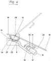
- the tongue 23 (as shown in FIG. 3) forms a channel with a concave, cylindrical inner surface 27. It is made in one piece with the inner cover part 18 and projects beyond its longitudinal edge 28.
- the distances of the tongue root and the free tongue end from the longitudinal edge 28 (FIG. 3) are at least approximately the same.
- the center of curvature 29 of the channel 27 lies above the cover 5 and forms the pivot axis between the inner and outer cover part 18 and 19.
- the complementary tongue 26 on the outer cover part 19 has on its underside a convex surface 30 with the same center of curvature 29 as the channel 27.
- the radius of curvature of the surface 30 is the same or slightly smaller than that of the channel 27.
- the free end and the root of the tongue 26 are approximately the same distance from the associated longitudinal edge 31 (FIG. 3) of the outer cover part 19, as a result of which the longitudinal edges 28 and 31 adjoin one another almost seamlessly in the assembled state of the cover.
- the tongues 23 and 26, when inserted one into the other, form a hinge-band-like and positively secured swivel connection with a center of curvature 29 as the swivel axis.
- this swivel connection is established in that the outer cover part 19 is inserted into the groove 27 in an inclined position with its free tongue end first (shown in broken lines in FIG. 2) and then swiveled downward until the L-profile rib 25 rests with its free leg on the clamping body 17.
- the cover parts 18 and 19 are now connected to one another in a form-fitting and hinge-like manner.
- the cover is then moved in the direction of arrow 32 (FIG. 2) against the wall surface 2, the free legs of the L-profile ribs 22 and 25 being pushed into the corresponding claws 10 and 11 at the same time.
- the pivot axis 29 or the center of curvature of the tongues 23 and 26 can lie on the cutting line of the inner or outer covering part 18 or 19.
- the cover 5 has bores 34 on the end face for receiving threaded bolts (FIGS. 1 and 2). These holes 34 allow shuttering plates 35 to be screwed to the cover 5 on the end faces of the awning. The holes 34 also serve to receive centering pins if two or more covers 5 are to be butted against each other in the case of very long awnings.
Landscapes
- Engineering & Computer Science (AREA)
- Architecture (AREA)
- Civil Engineering (AREA)
- Structural Engineering (AREA)
- Building Awnings And Sunshades (AREA)
Applications Claiming Priority (2)
| Application Number | Priority Date | Filing Date | Title |
|---|---|---|---|
| CH3054/92 | 1992-09-30 | ||
| CH305492A CH686583A5 (de) | 1992-09-30 | 1992-09-30 | Abdeckung fur eine Markise. |
Publications (2)
| Publication Number | Publication Date |
|---|---|
| EP0590249A2 true EP0590249A2 (fr) | 1994-04-06 |
| EP0590249A3 EP0590249A3 (en) | 1995-08-16 |
Family
ID=4247581
Family Applications (1)
| Application Number | Title | Priority Date | Filing Date |
|---|---|---|---|
| EP93110971A Withdrawn EP0590249A3 (en) | 1992-09-30 | 1993-07-09 | Covering for outside awning |
Country Status (2)
| Country | Link |
|---|---|
| EP (1) | EP0590249A3 (fr) |
| CH (1) | CH686583A5 (fr) |
Cited By (2)
| Publication number | Priority date | Publication date | Assignee | Title |
|---|---|---|---|---|
| EP1873339A2 (fr) | 2006-06-29 | 2008-01-02 | GEZE GmbH | Installation de porte |
| EP1900888A3 (fr) * | 2006-08-31 | 2009-01-14 | Llaza, S.A. | Ensemble de caisson pour auvent enroulable |
Family Cites Families (1)
| Publication number | Priority date | Publication date | Assignee | Title |
|---|---|---|---|---|
| DE9000939U1 (de) * | 1990-01-29 | 1990-04-12 | Warema Renkhoff Gmbh & Co Kg, 8772 Marktheidenfeld | Schutzabdeckung für eine Gelenkarm-Markise |
-
1992
- 1992-09-30 CH CH305492A patent/CH686583A5/de not_active IP Right Cessation
-
1993
- 1993-07-09 EP EP93110971A patent/EP0590249A3/de not_active Withdrawn
Cited By (3)
| Publication number | Priority date | Publication date | Assignee | Title |
|---|---|---|---|---|
| EP1873339A2 (fr) | 2006-06-29 | 2008-01-02 | GEZE GmbH | Installation de porte |
| EP1873339A3 (fr) * | 2006-06-29 | 2008-06-11 | GEZE GmbH | Installation de porte |
| EP1900888A3 (fr) * | 2006-08-31 | 2009-01-14 | Llaza, S.A. | Ensemble de caisson pour auvent enroulable |
Also Published As
| Publication number | Publication date |
|---|---|
| CH686583A5 (de) | 1996-04-30 |
| EP0590249A3 (en) | 1995-08-16 |
Similar Documents
| Publication | Publication Date | Title |
|---|---|---|
| EP0445591A1 (fr) | Dispositif d'accouplement pour une colonne de direction d'un véhicule automobile avec la queue de l'arbre d'un mécanisme de direction | |
| DE69500214T2 (de) | Universale Rohrschelle | |
| CH649802A5 (en) | Panel-securing means for facade or roof structures | |
| DE2543897C3 (de) | Vorrichtung zum Halten eines rohrförmigen Handlaufs | |
| EP0590249A2 (fr) | Couverture pour marquise | |
| DE2305394A1 (de) | Fassadenplatte | |
| DE3423106A1 (de) | Abstandhalter fuer elektrische leiter, insbesondere fuer blitzschutzleiter | |
| DE8701832U1 (de) | Scharnierelement | |
| DE3519948C2 (de) | Vorrichtung zur Halterung von Langformgütern an Gebäudeteilen | |
| EP0614037A1 (fr) | Support fixé au plafond | |
| DE69101528T2 (de) | Befestigungselement für ein Rohr, insbesondere für die Abfuhr von Regenwasser. | |
| DE202021104587U1 (de) | Verbinderhalterung zum Verbinden eines Abdeckelementsund eines Verkleidungselements mit einem Fensterrahmen und solch eine Verbinderhalterung umfassendesDachfenster | |
| EP0086329A1 (fr) | Dispositif d'assemblage | |
| DE60002940T2 (de) | Eckverbindung für Rahmenleisten | |
| DE9403136U1 (de) | Schnapprohrschelle | |
| AT402988B (de) | Kabelführungsvorrichtung | |
| DE60012109T2 (de) | Klammer | |
| DE7923561U1 (de) | Hand- oder schutzstangeneinrichtung | |
| DE20102455U1 (de) | Vorrichtung zur Befestigung eines Einbauelements in die Einbauöffnung einer Tragplatte | |
| AT360890B (de) | Vorrichtung zum befestigen von einem mit einer grundplatte versehenen koerper, insbesondere einem skibindungsteil | |
| DE9104102U1 (de) | Haltevorrichtung für den Flächenreflektor einer Satellitenantenne | |
| DE3210820A1 (de) | Dosiergeraet | |
| DE20112824U1 (de) | Profilschiene und Befestigungsvorrichtung mit Profilschiene | |
| DE102007030728B4 (de) | Profilleisten-Vorrichtung | |
| DE2245042A1 (de) | Verdrehsicherung fuer vorzugsweise in gewindedurchzuegen von blechteilen angeordnete schrauben |
Legal Events
| Date | Code | Title | Description |
|---|---|---|---|
| PUAI | Public reference made under article 153(3) epc to a published international application that has entered the european phase |
Free format text: ORIGINAL CODE: 0009012 |
|
| AK | Designated contracting states |
Kind code of ref document: A2 Designated state(s): AT DE FR IT |
|
| PUAL | Search report despatched |
Free format text: ORIGINAL CODE: 0009013 |
|
| AK | Designated contracting states |
Kind code of ref document: A3 Designated state(s): AT DE FR IT |
|
| 17P | Request for examination filed |
Effective date: 19950904 |
|
| 17Q | First examination report despatched |
Effective date: 19970115 |
|
| STAA | Information on the status of an ep patent application or granted ep patent |
Free format text: STATUS: THE APPLICATION IS DEEMED TO BE WITHDRAWN |
|
| 18D | Application deemed to be withdrawn |
Effective date: 19970527 |