EP0590284A2 - Batteriepol, Verfahren zum Kaltformen und dazugehörender Apparat zur Herstellung solcher Batteriepole - Google Patents
Batteriepol, Verfahren zum Kaltformen und dazugehörender Apparat zur Herstellung solcher Batteriepole Download PDFInfo
- Publication number
- EP0590284A2 EP0590284A2 EP93112810A EP93112810A EP0590284A2 EP 0590284 A2 EP0590284 A2 EP 0590284A2 EP 93112810 A EP93112810 A EP 93112810A EP 93112810 A EP93112810 A EP 93112810A EP 0590284 A2 EP0590284 A2 EP 0590284A2
- Authority
- EP
- European Patent Office
- Prior art keywords
- battery terminal
- die
- lead
- slug
- punch
- Prior art date
- Legal status (The legal status is an assumption and is not a legal conclusion. Google has not performed a legal analysis and makes no representation as to the accuracy of the status listed.)
- Granted
Links
Images





Classifications
-
- H—ELECTRICITY
- H01—ELECTRIC ELEMENTS
- H01M—PROCESSES OR MEANS, e.g. BATTERIES, FOR THE DIRECT CONVERSION OF CHEMICAL ENERGY INTO ELECTRICAL ENERGY
- H01M50/00—Constructional details or processes of manufacture of the non-active parts of electrochemical cells other than fuel cells, e.g. hybrid cells
- H01M50/50—Current conducting connections for cells or batteries
- H01M50/543—Terminals
- H01M50/552—Terminals characterised by their shape
- H01M50/561—Hollow metallic terminals, e.g. terminal bushings
-
- B—PERFORMING OPERATIONS; TRANSPORTING
- B21—MECHANICAL METAL-WORKING WITHOUT ESSENTIALLY REMOVING MATERIAL; PUNCHING METAL
- B21K—MAKING FORGED OR PRESSED METAL PRODUCTS, e.g. HORSE-SHOES, RIVETS, BOLTS OR WHEELS
- B21K21/00—Making hollow articles not covered by a single preceding sub-group
- B21K21/08—Shaping hollow articles with different cross-section in longitudinal direction, e.g. nozzles, spark-plugs
-
- Y—GENERAL TAGGING OF NEW TECHNOLOGICAL DEVELOPMENTS; GENERAL TAGGING OF CROSS-SECTIONAL TECHNOLOGIES SPANNING OVER SEVERAL SECTIONS OF THE IPC; TECHNICAL SUBJECTS COVERED BY FORMER USPC CROSS-REFERENCE ART COLLECTIONS [XRACs] AND DIGESTS
- Y02—TECHNOLOGIES OR APPLICATIONS FOR MITIGATION OR ADAPTATION AGAINST CLIMATE CHANGE
- Y02E—REDUCTION OF GREENHOUSE GAS [GHG] EMISSIONS, RELATED TO ENERGY GENERATION, TRANSMISSION OR DISTRIBUTION
- Y02E60/00—Enabling technologies; Technologies with a potential or indirect contribution to GHG emissions mitigation
- Y02E60/10—Energy storage using batteries
Definitions
- This invention relates generally to battery terminals and an improved method of making battery terminals by cold forming.
- Our corresponding prior art application discloses cold forming battery terminals through the process of forming a lead slug into a cylindrical cup and then punching out the end of the lead slug while expanding the lead slug radially outward into a die having the shape of a finished battery terminal.
- the present invention comprises improvements to the aforementioned process by permitting one to cold form a battery terminal with a necked down region extending around the flanges of the battery terminal.
- cold forming metals The process of cold forming metals is well known in the art. Typically a deformable or malleable metal is deformed at room temperature through a series of compression and/or expansion steps. Cold forming has been used to form various articles including automotive items such as spark plug housings and battery terminals. Typically, spark plug housings are made of steel alloys and other articles, including battery terminals, are made of softer metals such as lead or lead alloys. While cast battery terminals have been used satisfactorily, cold formed battery terminals may be preferable since the working of the metals during the cold forming process appears to remove air pockets. The result is a more dense terminal that hinders electrolyte from escaping through the terminal.
- the present invention provides a process for cold forming a lead slug into a finished battery terminal with a necked down region that can be directly inserted into a battery container.
- the invention produces a battery terminal with high torque resistance utilizing three sided frusto-conical terminal recesses that coact with mating protrusions extending from the battery container.
- the method is a horizontal cold forming process to form a finished battery terminal from a preworked lead slug by driving one end of a punch through the slug so that the one end forms an axial opening through the slug and removes excess material, a first and second portion of the punch closes the die chamber and a third portion of the punch radially expands the lead slug into a completed or finished battery terminal.
- the dies for forming the battery terminal include a movable four-segmented die for collapsing radially inward around the slug and a frusto-conical die for forming the top portion of the battery terminal.
- An ejector sleeve removes the finished battery terminal after the cold forming process is completed.
- the invention includes a cold-forming method of making a finished battery terminal with a necked down flange by first expanding the metal radially outward until the battery terminal die cavity is partially filled with metal and then upsetting the metal to complete the deformation filling of the battery terminal die cavity and to simultaneously form a necked down region in the flange on the battery terminal.
- reference numeral 10 generally identifies a cold formed high torque lead battery terminal as it appears in a thermoplastic battery container 11.
- Figure 2 shows terminal 10 with a central or axial through passageway or opening 14 which will be subsequently filled with molten lead to form a mechanical and electrical connection to a battery grid within the battery container.
- FIG 2 Figure 2 and Figure 4 show battery terminal 10 integrally formed or secured to battery container 11 in a torque resistant relationship by the coaction of terminal torque lock regions 15 and a moldable container material 19 such as a thermoplastic resin.
- Annular rings 19a of the container material 19 fill a set of annular openings located between parallel spaced acid-sealing rings 16, 17 and 18 which extend radially outward from terminal 10.
- Battery terminal 10 has a frusto-conical shaped hollow top portion 12 with an outer facing 13 for forming electrical connection with a battery connector.
- protrusion member 20 has a massive base since the protrusion member extends vertically upward from annular cover member 20a that abuts against acid ring 16. The result is protrusion members 20 that are vertically restrained in container 11 by terminal ring 13a and acid ring 16.
- Figure 3 shows an end view of torque locks 15 that form a series of three sided general pyramid-like recesses 15 in the skirt of battery post 10.
- the recesses 15 are characterized in that they have a base dimension W1 which is substantially larger than the top dimension W2 so that the mating protrusions in battery container material 19, which fit into recesses 15, have a massive support base which tapers toward a narrower top.
- Figure 4 shows a sectional view taken along line 4-4 of figure 3 to illustrates how the battery container material, which forms three sided pyramid-like protrusions members 20, projects into torque locks 15 to thereby form circumferentially spaced retaining lugs for locking battery terminal 10 to container 11.
- Torque locks 15 are located circumferentially around terminal 10. Torque locks 15 are equal distance from one another with center lines C x extending through each of the torque locks to intersect at a central point P. The use of the torque locks 15 in battery terminal allows one to provide a substantially strong and rigid torque resistant support between battery terminal 10 and container 11.
- the inward projecting members 20 are spaced circumferentially around the periphery of the battery terminal 10 and project inward. Twelve three sided projecting members 20 are located around the periphery of battery terminal 10 to integrally engage twelve torque locks on terminal 10.
- the terminal 10 is readily adaptable to forming through a horizontal cold forming process that converts an extruded lead slug into a finished battery terminal for mounting in a battery container.
- Figure 5 shows a cylindrical lead slug 40 formed through a conventional extrusion process.
- Lead slug 40 has a cylindrical outer surface 42, a first end 43 and a second end 41.
- the diameter of the slug is designated by D1 and the length of the slug is designated by L1.
- the slug Prior to forming slug 40 into a finished battery terminal the slug is worked and shaped to square up the ends and the diameter of the slug so that the cold forming of the battery terminal can be performed in a single cold forming operation.
- the pre-working of the lead is desirable since the lead cold forms better if the lead has been pre-worked.
- Figure 6 shows lead slug 40 after further partial pre-working. Slug end faces 41 and 43 have been squared while the diameter D2 remains substantially the same as diameter D1 . As a result of the end squaring process, the length L2 of slug 30 may be slightly shorter than the length L1 of the slug prior to the pre-working step.
- Figure 7 shows the cylindrical lead slug 40 after the final pre-working step that produces a slug for cold forming.
- a cylindrical punch has been directed into a central portion of end 41 of slug 40 to produce a cylindrical cavity 43 that extends about half the depth of the lead slug with a diameter D4.
- slug 40 increases in length because the punch forces the lead in the central portion of the slug to flow onto the end of the slug as the lead slug is confined by a cylindrical chamber (not shown) of diameter D2.
- slug 40 has an outer diameter of diameter D2 and a cavity of diameter D4 .
- the slug is now ready for cold forming into a finished battery terminal.
- the purpose of the preworking of the lead slug is to prepare the metal for cold forming since preworked metal is easier to cold form.
- the cold forming produces suitable dimensions on the lead slug to permit the cold forming process through coaction of a die and punch. While slug 40 is shown with a cavity 43 that extends about half way into slug 40, the cavity 43 may be formed in different depths. In certain applications, cavity 43 could extend completely through the lead slug and in other applications lead slug 40 can be processed without any cavity.
- Figures 8 through 12 show the process of forming the pre-worked cylindrical lead slug 40 into a battery terminal in greater detail.
- Reference numeral 50 identifies a movable die case and reference numeral 70 identifies a stationary die case.
- Reference numeral 49 identifies upper and lower members for moving movable die case along central axis 48.
- Preworked lead slug 40 is shown located on end 57 of a punch 52 which includes numerous cylindrical stepped sections as well as frusto-conical connecting regions.
- Punch 52 includes a cylindrical end face 53, a frusto-conical connecting region 54, a cylindrical section 55, a further frusto-conical connecting region 56, a cylindrical section 57 having an end surface 58.
- section 57 is slightly more than the diameter D4 so that lead slug 40 is maintained on punch section 57 through frictional engagement between slug 40 and punch section 57.
- Punch 52 is powered by a source (not shown) and slides within a sleeve 63 which sliding supports a four-part radially collapsible die section 50a which is axially displaceable in die case 50.
- Quadrant segments 60 and 61 of die section 50a are shown in figure 8.
- Figure 8A shows an end view of movable die 50 to illustrate all four segments 60, 61, 62 and 63.
- Die segments 60, 61, 62 and 63 slide on frusto conical surface 64 to permit each of the die segments to be displaced axially and radially around lead slug 40.
- a set of radial pins 50c, 50d, 50b, and 50e extend inward to act as stops for the die segments, a set of cross pins 60a, 61a, 60b, and 61b act as lateral guides to permit the die segments to move radially inward while maintaining alignment with each other.
- the front of movable die case 50 contains a frusto conical guide surface 64 so that die segments 60, 61, 62 and 63 can be collapsed around slug 40.
- the die segments 60, 61, 62 and 63 can be collapsed around lead slug 40 the die segments 60, 61, 62 and 63 do not do any deforming of the lead slug 40 during the collapsing step. That is the die segments 60, 61, 62 and 63 collapse to form a die chamber having the shape of the lower portion of a battery terminal which contains the protrusions and recesses to form acid sealing rings 16,17 and 18.
- the companion to movable die case 50 is stationary die case 70; which includes an outer member 71 and a die 72 for forming the top portion 12 of a battery terminal.
- Die 72 contains a frusto-conical section 73 which forms the cavity 73 for forming the top portion of a battery terminal.
- An ejector sleeve 74 slides within die 72.
- Ejector sleeve 74 includes an end surface 74a, a first inner surface 75 and a second inner surface 77 of slightly larger diameter.
- a waste retaining lip 76 connects first inner surface 75 and second inner surface 77.
- Located to the right of ejector sleeve 74 is a passage 78 for discharging lead removed during the cold working of the lead slug.
- the end of die 70 includes members 80 which abut against the closed four split die segments 60, 61, 62 and 63 when die 50 is moved axially against stationary die 70.
- Figures 9 and 10 illustrate the cooperative relationship of die 50 and die 70.
- Figure 9 shows lead slug 40 confined in the die segments 60, 61, 62 and 63 and die section 72.
- An end of slug 40 is shown partially displaced by end 58 of punch section 57.
- Punch section 57 is completing the formation of a through hole in lead slug 40 by forcing a portion 40a of lead slug 40 through the interior of ejection sleeve 74.
- lead slug 40 is not radially expanded outward although the die segments 60, 61, 62 and 63 and die section 72 do not prevent radially outward deformation of lead slug 40.
- Figure 10 illustrates the cold forming process in a more advanced state with slug 40 radially deformed and separated from excess lead 40a.
- Figure 10 shows that cylindrical punch section 55 has radially expanded the hollowed lead slug radially outward into die segments 60, 61, 62 and 63 and die section 72 to form a finished battery terminal.
- Waste lead 40a is located on the inside of ejector sleeve 74 and pushes waste lead slugs 40b located in ejector sleeve 74.
- waste lead 40c is pushed out of ejector sleeve 74 by waste lead 40a and waste lead 40b as shown in figure 10. Waste lead 40c falls out passage 78.
- Figure 11 illustrates movable die 50 in a retracted position with lead slug 40 formed into a finished battery terminal which is frictionally held by the sides of die section 72 of die 70.
- Figure 12 illustrates ejector sleeve 74 forcing finished battery terminal 40 out of stationary die 70.
- a cylindrical cupped shaped lead slug is placed into a die and in a single operation a stepped punch forms a through opening in the lead slug, removes excess lead from the lead slug and radially deforms the remaining portion of the lead slug into a finished battery terminal ready for mounting into a battery container.
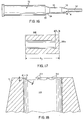
- FIG. 13 is an enlarged view of interior cylindrical surfaces 74 and 75 which are connected by a cylindrical lip 76.
- the purpose of lip 76 is to provides a means for catching the waste lead 40a so that as pin 57 is withdrawn from slug 40 lip 76 prevents waste slug 40a from being pulled back with punch 57.
- Figure 14 illustrate the final expansion of the lead slug as the first portion of cylindrical punch 55 seals off one end of the die chamber around lead slug 40.
- Figure 14 shows an enlarged view of lead slug 40 at the moment the die chamber for forming the lead slug into a battery post or terminal is completely confined.
- the cylindrical punch surface 55 has an outside diameter that closely fits within the opening of ejector sleeve 74 to seal off one end of the die chamber for the lead slug.
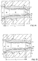
- Figure 16 reference numeral 52 identifies the improved step punch which is generally shown in Figures 8-12.
- a frusto-conical section 56 which forms a transition section between end cylindrical section 57 and the intermediate cylindrical section 55 of punch 52. It has been discovered that controlling the transition cone angle theta on punch 52 generally reduces the flash present in the finished part.
- flash 101 comprises a thin section of extruded metal which extends radially inward a distance y and downward a distance x. While the size of the flash may vary, the typical flash may have an x dimension of .005 Inches and a y dimension of .005 inches with a thickess z of .0001 inches. Since the internal region 103 is to be filled with lead, the presence of flash 101 in the interior region normally causes no problems. However, if the terminals are handled roughly, flash 101 may flake off and fall into the plastic used to mold the battery cover around the battery terminal, thereby creating the possibility for introducing a short in the battery.
- the improvement in the process comprises a method and means for eliminating the flash.
- One of the known ways to eliminate flash is to have the exact amount of lead necessary to expand into die 130. Another is to have the lead positioned in the die so it uniformly fills the die during the cold forming process. Unfortunately, precisely controlling the amount of lead to fill up the die is difficult to do during a cold forming process.
- slug 100 (Figure 17) is shown having a bottom thickness designated by b t.
- the purpose of having a cylindrical bottom 100a is to facilitate handling of the lead slug during the forming steps; that is, the bottom section 100a of slug 100 allows end of pin 57 to positively engage slug 100 and force the slug to seat against the end of sleeve 74 ( Figure 9 and 19).
- FIG 19 shows die 130 and multi-step punch 52 coacting to radially expand lead slug 100 into a battery terminal.
- punch 52 is shown with a portion of the forward travel of the punch yet to be completed, and Figure 20 shows punch 52 with the forward travel completed.
- Figure 19 illustrates that during the radial expansion process, excess lead 101 extends in an annular shaped section 101 and is forced forward of section 56 as punch 52 moves forward.
- vent passages 120 and 121 Located peripherally around die 130 are a series of narrow, elongated vent passages 120 and 121. Vent passage 121 connects to a larger discharge passage 123, and vent passage 120 connects to a larger discharge passage 122.
- the vent passages are narrow to allow air to escape and are placed at the end of the die to prevent the vent passage from acting as a die cavity.
- vent passages 120 and 121 may have a width of up to 0.125-inches but have a depth d x of only about 0.0005-inches. The small depth vent passages allow air to escape and thus avoid local deformation as a result of air trapped within the die. While only two vent passages are shown, one may prefer to radially space more or less vent passages. Typically, four to six vent passages radially spaced around die 130 provide means for removing trapped air from the die.
- Figure 19 illustrates another feature of the process.
- end plug 100a located on the end of pin 57.
- End plug 100a was forced out of the bottom of slug 100 ( Figure 17) to provide an annular slug 100 for radially expansion within die 130. Due to the rapid forward motion (indicated by arrows) of pin 52, end plug 100a is forced outward of ejector sleeve 74 and drops off the end of pins 57 ( Figure 20) as pin 52 reaches the end of its forward travel. Thus, a first portion of excess lead 100a is removed from slug 100 by pin 57 with a shearing or punching process.
- the second portion of excess lead removed from slug 100 comprises annular lead member 101 (Figure 19) which is being formed around transition section 56 as lead is being forced radially outward and forward in front of section 56.
- annular waste lead member 101 is sheared from the end of slug 100 by co-action of punch section 55 with die 130 and the end of sleeve 74.
- Extending centrally through punch 52 is a central axis 110.
- Central axis 110 is concentric with die 130 and sleeve 74.
- Figure 19 shows frusto-conical transition section 56 located between and smoothly connecting cylindrical pin sections 55 and 57 to each other.
- the transition zone 56 is maintained at an angle theta which is less than 15 degrees. Preferably an 11 degree transition angle is preferred.
- the transition angle theta the greater the pressure build-up in the die and the greater the chances for flash occurring during the cold forming of the terminal through a radial expansion process.
- the less the transition angle the longer the transition zone 56.
- the excess metal 101 is sheared from the end of terminal 101 without creating excess deformation forces that force metal in the form of a flash between the outside of a die section 55 and the interior sleeve 74. While the optimal transition zone angle may vary with different components, one can readily determine the proper angle by observing the finished part. If the finished part is not completely filled out, the transition angle may be too shallow. Conversely, if the transition angle is too high, excessive deformation pressure is provided in the die forcing flash from parting surfaces between die 130 and sleeve 74.
- FIGS. 21 and 22 illustrate such a battery terminal which is difficult to cold form.
- Figure 21 shows a side view of such a battery terminal
- Figure 22 shows a cross sectional view of the terminal.
- Figure 21 shows the battery terminal 150 having a frusto-conical top 151, a radially extending cylindrical flange 152 with a radial extending cylindrical skirt 153 located therearound.
- a series of rectangular shaped lugs 154 extend downward from flange 154 and radially outward from lower terminal section 155.
- Figure 22 shows a V-shaped groove 156 extending completely around the underside of flange 152.
- the presence of the V-shaped groove 156 creates problems in conventional cold forming of battery terminals. That is, in the process of cold forming battery terminals, the lead is deformed radially outward by a punch until a die cavity is completely filled, thereby forming the finished battery terminal. For the lead to be deformed radially outward for forming the battery terminal shown in Figures 21 and 22, the lead must not only flow radially outward but it must flow backward around the narrowed portion of the V-shaped groove 156.
- the V-shaped groove is shown in greater detail in Figure 22.
- flange 152 extends radially outward with a skirt 153 located radially outward of groove 156.
- the arrows indicate the general radial outward flow of metal during the cold forming process. If the V-groove 156 is not present, the metal can be radially formed outward as illustrated in Figures 8-12. However, the deformation of metal around the apex of 156 in order to form skirt 153 becomes difficult since excessive pressures are required which may cause flashing between the dies and, in certain instances, voids may be left in the cavity resulting in a defective battery terminal.
- the present process provides a method and apparatus for cold forming battery terminals which have a narrowed neck or necked down region located in the flange of the battery terminal.
- a narrowed neck or necked down region located in the flange of the battery terminal.
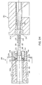
- Figure 24 shows a movable die 200 and a stationary die 201.
- Die 201 is similar to die 70 and includes a die cavity 220 having a frusto-conical recess 221 for forming the top portion of a battery terminal.
- Movable die 200 includes a slidable punch 202.
- Punch 202 includes an annular end face 213, a cylindrical section 203, a frusto-conical connecting region 205, a further frusto-conical region 206, and a cylindrical section 207 having an end surface 216.
- section 207 is slightly larger than the inside diameter of the lead slug 150 so the lead slug is maintained in frictional contact on punch section 207 through frictional engagement between slug 150 and punch section 207.
- Punch 202 is powered by a source not shown and slides within a sleeve 263.
- a sleeve die 204 for forming the annular V-shaped groove in the underside of the battery terminal flange as well as the locking lugs located around the periphery of the battery terminal shown in Figures 21 and 22.
- Figure 24 shows lead slug 150 held on pin 207 in a position between die 200 and 201. In this position, the slug is ready to begin the process of deformation.
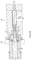
- Figure 25 shows the die 200 abutting against die 201 with punch 202 extending into and through lead slug 150.
- Figures 25 shows lead slug 150 being forced radially outward into the cavity 221a.
- the end of slug 175 is shown being forced out of die 201.
- the end of die sleeve 204 rests against punch end face 213 through the action of a compression spring 215 located in annular chamber 216. Note that in the position shown in Figure 25, the metal 150a only partially fills the battery terminal cavity 221a.
- Figure 26 illustrates the beginning of the formation of the neck in the flange area of a battery terminal. Note that die sleeve 204 is moved forward a distance x p by cylindrical end face 213. Spring 215 compresses to allow forward motion of die sleeve 204.
- the lead 150b located radially outward forms flange 152 with the slidable die 204 axially slidable along pin 202 to form the V-groove in the underside of flange 152.
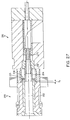
- Figure 27 shows pin 202 at the bottom of its stroke with sleeve 204 extending a distance noted by x f. Note that spring 15 is fully compressed in annular chamber 216. This is in a later portion of the stroke. The opposite end of sleeve 202 actually deforms and necks down the flange 152 to form the V-shaped groove or acid ring on the underside of flange 152. With the die sleeve in the position shown in Figure 27, the battery terminal 150 is in the finished condition and is ready for use.
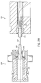
- Figure 28 shows the dies 200 and 201 separated with the finished battery terminal 150 ready for removal by ejector sleeve 223. Note that die sleeve 204 returns to its retracted condition with compression spring 215 expanding to displace die sleeve 204 to the left into a position for forming another battery terminal.
Landscapes
- Engineering & Computer Science (AREA)
- Mechanical Engineering (AREA)
- Chemical & Material Sciences (AREA)
- Chemical Kinetics & Catalysis (AREA)
- Electrochemistry (AREA)
- General Chemical & Material Sciences (AREA)
- Connection Of Batteries Or Terminals (AREA)
- Hybrid Cells (AREA)
- Forging (AREA)
Applications Claiming Priority (6)
| Application Number | Priority Date | Filing Date | Title |
|---|---|---|---|
| US940391 | 1992-09-03 | ||
| US07/940,391 US5296317A (en) | 1992-09-03 | 1992-09-03 | High torque battery terminal and method of making same |
| US16370 | 1993-02-11 | ||
| US08/016,370 US5349840A (en) | 1992-09-03 | 1993-02-11 | Method of making a high torque battery terminal |
| US29869 | 1993-03-11 | ||
| US08/029,869 US5373720A (en) | 1992-09-03 | 1993-03-11 | Method of making battery terminal with necked flange |
Publications (3)
| Publication Number | Publication Date |
|---|---|
| EP0590284A2 true EP0590284A2 (de) | 1994-04-06 |
| EP0590284A3 EP0590284A3 (de) | 1995-06-07 |
| EP0590284B1 EP0590284B1 (de) | 1997-06-18 |
Family
ID=27360549
Family Applications (1)
| Application Number | Title | Priority Date | Filing Date |
|---|---|---|---|
| EP93112810A Expired - Lifetime EP0590284B1 (de) | 1992-09-03 | 1993-08-10 | Batteriepol, Verfahren zum Kaltformen und dazugehörender Apparat zur Herstellung solcher Batteriepole |
Country Status (7)
| Country | Link |
|---|---|
| US (1) | US5373720A (de) |
| EP (1) | EP0590284B1 (de) |
| JP (1) | JP3841836B2 (de) |
| AT (1) | ATE154727T1 (de) |
| CA (1) | CA2103759C (de) |
| DE (1) | DE69311660T2 (de) |
| ES (1) | ES2104008T3 (de) |
Cited By (10)
| Publication number | Priority date | Publication date | Assignee | Title |
|---|---|---|---|---|
| EP0836237A1 (de) * | 1996-10-09 | 1998-04-15 | Osvaldo Balbino Casais | Gratfreier korrosionsbeständiger Pol mit kurzer Verankerung für Speicherbatterien |
| EP1347522A1 (de) * | 2002-03-20 | 2003-09-24 | I.C.S. Industria Composizioni Stampate S.p.A. | Kabelanschlusskleme für Batteriepol |
| GB2420300A (en) * | 2004-11-17 | 2006-05-24 | Accuma Plastics Ltd | Method and apparatus for the manufacture of a terminal for a lead-acid type accumulator and a terminal manufactured therewith |
| WO2011110317A1 (de) * | 2010-03-09 | 2011-09-15 | Vb Autobatterie Gmbh & Co. Kgaa | Anschlusspol für einen akkumulator und akkumulatorgehäuse |
| WO2014088390A3 (es) * | 2012-12-06 | 2014-09-04 | KURT-MAYRL-Y-SANCHEZ-JUAREZ, Jose-Antonio | Aparato y metodo para la fabricacion de terminales para baterias |
| US9748551B2 (en) | 2011-06-29 | 2017-08-29 | Water Gremlin Company | Battery parts having retaining and sealing features and associated methods of manufacture and use |
| US9917293B2 (en) | 2009-04-30 | 2018-03-13 | Water Gremlin Company | Battery parts having retaining and sealing features and associated methods of manufacture and use |
| US9954214B2 (en) | 2013-03-15 | 2018-04-24 | Water Gremlin Company | Systems and methods for manufacturing battery parts |
| US10283754B2 (en) | 2004-01-02 | 2019-05-07 | Water Gremlin Company | Battery parts and associated systems and methods |
| US11038156B2 (en) | 2018-12-07 | 2021-06-15 | Water Gremlin Company | Battery parts having solventless acid barriers and associated systems and methods |
Families Citing this family (16)
| Publication number | Priority date | Publication date | Assignee | Title |
|---|---|---|---|---|
| DE19633463A1 (de) * | 1995-09-02 | 1997-03-06 | Basf Magnetics Gmbh | Verfahren zur Herstellung von Elektroden |
| US7628049B2 (en) | 2001-06-14 | 2009-12-08 | Tulip Corporation | Method and apparatus for manufacturing a battery terminal with undercut rings |
| US6701998B2 (en) | 2002-03-29 | 2004-03-09 | Water Gremlin Company | Multiple casting apparatus and method |
| US7905384B1 (en) | 2002-06-04 | 2011-03-15 | Tulip Corporation | Cold formed battery terminal |
| US7163763B2 (en) * | 2002-06-04 | 2007-01-16 | Tulip Corporation | Cold formed battery terminal |
| CA2454527A1 (en) * | 2003-03-18 | 2004-02-19 | Pem Management, Inc. | Cold-headed standoff |
| US20040182209A1 (en) * | 2003-03-18 | 2004-09-23 | Franco James S. | Cold-headed standoff |
| US6902095B2 (en) * | 2003-07-03 | 2005-06-07 | Water Gremlin Company | Two part cold formed battery terminal |
| US7338539B2 (en) | 2004-01-02 | 2008-03-04 | Water Gremlin Company | Die cast battery terminal and a method of making |
| GB0604094D0 (en) * | 2006-03-01 | 2006-04-12 | Ibm | Methods, apparatus and computer programs for navigating within a user interface |
| EP2286479A4 (de) * | 2008-05-19 | 2012-12-26 | Aquila Piombo Srl | Batterieteile und diesbezügliche herstellungs- und verwendungsverfahren |
| US8869377B2 (en) * | 2010-12-07 | 2014-10-28 | Shreyas R. Mehta | Integrated valve sleeve |
| WO2014141579A1 (ja) * | 2013-03-15 | 2014-09-18 | パナソニック株式会社 | 鉛蓄電池用ブッシングおよび鉛蓄電池 |
| JP6252747B2 (ja) * | 2013-11-22 | 2017-12-27 | ポップリベット・ファスナー株式会社 | 接合装置及び接合方法 |
| CN111085559B (zh) * | 2019-12-30 | 2025-12-19 | 泉州市一鸣交通电器有限公司 | 一种铅酸蓄电池接线端子成型设备 |
| KR102487205B1 (ko) * | 2021-11-05 | 2023-01-11 | 김진태 | 전기자동차용 배터리 단자 가공 금형 및 이를 이용한 가공 방법 |
Family Cites Families (38)
| Publication number | Priority date | Publication date | Assignee | Title |
|---|---|---|---|---|
| CA645083A (en) * | 1962-07-17 | Fischer Hans | Production of hollow bodies by pressing | |
| US1983618A (en) * | 1932-11-04 | 1934-12-11 | Pittsburgh Pipe & Coupling Com | Forging apparatus |
| US2599706A (en) * | 1946-06-26 | 1952-06-10 | Nat Machinery Co | Method for forging |
| GB734796A (en) * | 1951-12-27 | 1955-08-10 | Alfred Kreidler | A combined die-pressing and extrusion process and apparatus for the production of hollow bodies having protuberances on their outer face and one or more extensions at one end |
| US2901527A (en) * | 1958-05-28 | 1959-08-25 | Richardson Co | Battery cell cover |
| US3101534A (en) * | 1958-06-30 | 1963-08-27 | Textron Inc | Method of producing wrist pins or similar articles |
| US3113892A (en) * | 1958-12-01 | 1963-12-10 | Gould National Batteries Inc | Battery terminal post and cover construction |
| DE1146149B (de) * | 1959-02-26 | 1963-03-28 | Continental Gummi Werke Ag | Poldurchfuehrungsbuchse fuer elektrische Sammler |
| US3096579A (en) * | 1959-04-15 | 1963-07-09 | Burgess Norton Mfg Co | Process of producing extruded articles |
| CH371154A (de) * | 1959-08-21 | 1963-08-15 | Trelleborgs Gummifabriks Ab | Poldurchführung im Zellendeckel eines Akkumulators, insbesondere eines Bleiakkumulators |
| US3186209A (en) * | 1960-04-14 | 1965-06-01 | Nat Machinery Co | Method of cold forming an elongated hollow article |
| DE1259182B (de) * | 1962-01-18 | 1968-01-18 | Bosch Gmbh Robert | Vorrichtung zum Kaltpressen doppelnapffoermiger Zuendkerzengehaeuse |
| US3736642A (en) * | 1969-09-15 | 1973-06-05 | Gould Inc | Connection forming apparatus |
| DE2022163B2 (de) * | 1970-05-06 | 1972-12-14 | Varta Ag, 6000 Frankfurt | Automatisch arbeitende maschine zur herstellung von elektrischen akkumulatoren |
| GB1411632A (en) * | 1972-03-28 | 1975-10-29 | Lucas Electrical Co Ltd | Method of manufacturing a steel component having a head part and a hollow shank part |
| BE794053A (fr) * | 1972-04-13 | 1973-05-02 | Eltra Corp | Procede de realisation d'une connexion entre les elements d'un accumulateur electrique |
| US3842646A (en) * | 1973-04-20 | 1974-10-22 | Gleason Works | Process and apparatus for densifying powder metal compact to form a gear having a hub portion,and preferred powder metal compact shape for use therewith |
| US3947936A (en) * | 1974-08-12 | 1976-04-06 | General Motors Corporation | Coining expanded metal positive lead-acid battery grids |
| US3945097A (en) * | 1974-09-03 | 1976-03-23 | General Motors Corporation | Apparatus for making expanded metal lead-acid battery grids |
| PL102814B1 (pl) * | 1975-03-15 | 1979-04-30 | Instytut Obrobki Plastycznej | Sposob kucia wykorbien pojedynczych walow polskladanych,urzadzenie do kucia,zwlaszcza kucia wykorbien pojedynczych walow polskladanych i przyrzad do speczania zwlaszcza przedkuwek pojedynczych wykorbien walow polskladanych |
| US4362043A (en) * | 1975-09-17 | 1982-12-07 | Hanson Thomas A | Pipe unions |
| US4100674A (en) * | 1977-02-02 | 1978-07-18 | Tiegel Manufacturing Company | Method for making a side terminal weld |
| US4177551A (en) * | 1978-09-21 | 1979-12-11 | General Motors Corporation | Method of welding a arc battery intercell connector |
| US4291568A (en) * | 1979-08-27 | 1981-09-29 | Veeder Industries Inc. | Method of forming socket wrenches |
| US4358518A (en) * | 1980-05-27 | 1982-11-09 | General Motors Corporation | Wrought lead-calcium-strontium-tin (±barium) alloy for battery components |
| JPS5762831A (en) * | 1980-10-02 | 1982-04-16 | Nissan Motor Co Ltd | Forging die for part having reverse gradient |
| US4352283A (en) * | 1981-03-06 | 1982-10-05 | Ford Motor Company | Method of forming spark plug bodies |
| JPS57165155A (en) * | 1981-04-07 | 1982-10-12 | Toyota Motor Corp | Molding method for hollow cylindrical swaged material |
| US4422236A (en) * | 1981-10-01 | 1983-12-27 | General Electric Company | Method of extruding parts with captured fixture |
| US4416141A (en) * | 1982-01-11 | 1983-11-22 | The Nippert Company | Method and apparatus for forming an electrical connector |
| US4423617A (en) * | 1982-02-22 | 1984-01-03 | The Nippert Company | Method of making a male resistance welding electrode |
| JPS59141340A (ja) * | 1983-02-02 | 1984-08-14 | Hitachi Ltd | 段付中空部品の製造方法 |
| FR2540758B1 (fr) * | 1983-02-15 | 1986-03-07 | Meca Ind Speciales Atel | Outillage de formage a froid de pieces metalliques comportant des elements axiaux opposes |
| GB2141654A (en) * | 1983-06-20 | 1985-01-03 | Champion Spark Plug Co | Method of forming spark plug shells |
| US4662205A (en) * | 1985-10-21 | 1987-05-05 | Ratte Robert W | Machine for cold die casting malleable metals |
| IT1214528B (it) * | 1986-09-23 | 1990-01-18 | Aquila Piombo Per Caccia E Tir | Procedimento per la realizzazione di un polo o terminale di batteria elettrica, apparecchiatura per attuare tale procedimento, nonche'polo o terminale di batteria elettrica cosi' ottenuto. |
| JPH0620577B2 (ja) * | 1988-04-14 | 1994-03-23 | 日本特殊陶業株式会社 | 塑性加工による点火栓用端子ナットの製造方法 |
| US4945749A (en) * | 1989-10-30 | 1990-08-07 | General Motors Corporation | Cold forming dies and cold forming process |
-
1993
- 1993-03-11 US US08/029,869 patent/US5373720A/en not_active Expired - Lifetime
- 1993-08-10 DE DE69311660T patent/DE69311660T2/de not_active Expired - Lifetime
- 1993-08-10 AT AT93112810T patent/ATE154727T1/de not_active IP Right Cessation
- 1993-08-10 EP EP93112810A patent/EP0590284B1/de not_active Expired - Lifetime
- 1993-08-10 CA CA002103759A patent/CA2103759C/en not_active Expired - Fee Related
- 1993-08-10 ES ES93112810T patent/ES2104008T3/es not_active Expired - Lifetime
- 1993-09-03 JP JP22029693A patent/JP3841836B2/ja not_active Expired - Lifetime
Cited By (21)
| Publication number | Priority date | Publication date | Assignee | Title |
|---|---|---|---|---|
| EP0836237A1 (de) * | 1996-10-09 | 1998-04-15 | Osvaldo Balbino Casais | Gratfreier korrosionsbeständiger Pol mit kurzer Verankerung für Speicherbatterien |
| EP1347522A1 (de) * | 2002-03-20 | 2003-09-24 | I.C.S. Industria Composizioni Stampate S.p.A. | Kabelanschlusskleme für Batteriepol |
| US10283754B2 (en) | 2004-01-02 | 2019-05-07 | Water Gremlin Company | Battery parts and associated systems and methods |
| GB2420300A (en) * | 2004-11-17 | 2006-05-24 | Accuma Plastics Ltd | Method and apparatus for the manufacture of a terminal for a lead-acid type accumulator and a terminal manufactured therewith |
| GB2420300B (en) * | 2004-11-17 | 2007-01-10 | Accuma Plastics Ltd | Method and apparatus for the manufacture of a terminal for a lead-acid type accumulator and a terminal manufactured therewith |
| US7946033B2 (en) | 2004-11-17 | 2011-05-24 | Accuma Plastics Limited | Method and apparatus for manufacturing a lead terminal |
| US10910625B2 (en) | 2009-04-30 | 2021-02-02 | Water Gremlin Company | Battery parts having retaining and sealing features and associated methods of manufacture and use |
| US9917293B2 (en) | 2009-04-30 | 2018-03-13 | Water Gremlin Company | Battery parts having retaining and sealing features and associated methods of manufacture and use |
| US9935306B2 (en) | 2009-04-30 | 2018-04-03 | Water Gremlin Company | Battery parts having retaining and sealing features and associated methods of manufacture and use |
| US11942664B2 (en) | 2009-04-30 | 2024-03-26 | Water Gremlin Company | Battery parts having retaining and sealing features and associated methods of manufacture and use |
| WO2011110317A1 (de) * | 2010-03-09 | 2011-09-15 | Vb Autobatterie Gmbh & Co. Kgaa | Anschlusspol für einen akkumulator und akkumulatorgehäuse |
| US9847522B2 (en) | 2010-03-09 | 2017-12-19 | Johnson Controls Autobatterie Gmbh & Co. Kgaa | Connecting pole for a rechargeable battery and rechargeable battery housing |
| US10181595B2 (en) | 2011-06-29 | 2019-01-15 | Water Gremlin Company | Battery parts having retaining and sealing features and associated methods of manufacture and use |
| US9748551B2 (en) | 2011-06-29 | 2017-08-29 | Water Gremlin Company | Battery parts having retaining and sealing features and associated methods of manufacture and use |
| WO2014088390A3 (es) * | 2012-12-06 | 2014-09-04 | KURT-MAYRL-Y-SANCHEZ-JUAREZ, Jose-Antonio | Aparato y metodo para la fabricacion de terminales para baterias |
| US10217987B2 (en) | 2013-03-15 | 2019-02-26 | Water Gremlin Company | Systems and methods for manufacturing battery parts |
| US9954214B2 (en) | 2013-03-15 | 2018-04-24 | Water Gremlin Company | Systems and methods for manufacturing battery parts |
| US11038156B2 (en) | 2018-12-07 | 2021-06-15 | Water Gremlin Company | Battery parts having solventless acid barriers and associated systems and methods |
| US11283141B2 (en) | 2018-12-07 | 2022-03-22 | Water Gremlin Company | Battery parts having solventless acid barriers and associated systems and methods |
| US11804640B2 (en) | 2018-12-07 | 2023-10-31 | Water Gremlin Company | Battery parts having solventless acid barriers and associated systems and methods |
| US12308479B2 (en) | 2018-12-07 | 2025-05-20 | Otter Lake Technologies, Llc | Battery parts having solventless acid barriers and associated systems and methods |
Also Published As
| Publication number | Publication date |
|---|---|
| EP0590284B1 (de) | 1997-06-18 |
| JPH06208850A (ja) | 1994-07-26 |
| EP0590284A3 (de) | 1995-06-07 |
| CA2103759C (en) | 2004-05-25 |
| CA2103759A1 (en) | 1994-03-04 |
| DE69311660T2 (de) | 1998-01-08 |
| ATE154727T1 (de) | 1997-07-15 |
| US5373720A (en) | 1994-12-20 |
| ES2104008T3 (es) | 1997-10-01 |
| JP3841836B2 (ja) | 2006-11-08 |
| DE69311660D1 (de) | 1997-07-24 |
Similar Documents
| Publication | Publication Date | Title |
|---|---|---|
| EP0590284B1 (de) | Batteriepol, Verfahren zum Kaltformen und dazugehörender Apparat zur Herstellung solcher Batteriepole | |
| US5349840A (en) | Method of making a high torque battery terminal | |
| US4806301A (en) | Process of removing a plastic cap from a mold | |
| CA1186875A (en) | Method and apparatus for forming an electrical connector | |
| US4945749A (en) | Cold forming dies and cold forming process | |
| US4177237A (en) | Method of molding socket of plastic resin tube | |
| CA2459031C (en) | High torque battery terminal and method of making same | |
| EP2460216A1 (de) | Batterieteile sowie systeme und verfahren dafür | |
| CN109530471B (zh) | 一种薄壁近等高山形轻合金构件挤压成形模具 | |
| CN109530472B (zh) | 一种薄壁近等高山形轻合金构件挤压成形方法 | |
| JP3031647B2 (ja) | 粉末材料の押出し成形装置 | |
| US20090116932A1 (en) | Process for Producing Molded Article with Undercut, Forging Apparatus Therefor, and Intermediate Molded Object | |
| KR20030067736A (ko) | 샤프트 부분과 구형 헤드로 구성되는 볼트 요소와, 구성요소 조립체 및 볼트 요소 제조 방법 | |
| US4015461A (en) | Closed drop forging die | |
| CN110732618A (zh) | 镦制六角突缘螺栓的模具 | |
| DE1604712B1 (de) | Vorrichtung zum Herstellen eines tiefgezogenen Behaelteroberteils mit einer von einem Wulstrand umgebenen OEffnung | |
| US6009734A (en) | Process and device for manufacturing hollow sections with end-side cross-sectional expansions | |
| US3501790A (en) | Method of making blind rivet assemblies | |
| EP2293360B1 (de) | Batterieteil | |
| CA1150670A (en) | Closed chamber extrusion method and apparatus for shaping of metal rod into tulip-shaped part | |
| GB2067944A (en) | Extrusion process | |
| JP3269764B2 (ja) | ボス付きカップ状部材の塑性加工方法 | |
| GB2056327A (en) | Making cup-shaped cylindrical shells | |
| JPH0518663B2 (de) | ||
| JP2000317569A (ja) | 鍛造方法及び鍛造型 |
Legal Events
| Date | Code | Title | Description |
|---|---|---|---|
| PUAI | Public reference made under article 153(3) epc to a published international application that has entered the european phase |
Free format text: ORIGINAL CODE: 0009012 |
|
| AK | Designated contracting states |
Kind code of ref document: A2 Designated state(s): AT CH DE ES FR GB IE IT LI LU MC NL PT SE |
|
| PUAL | Search report despatched |
Free format text: ORIGINAL CODE: 0009013 |
|
| AK | Designated contracting states |
Kind code of ref document: A3 Designated state(s): AT CH DE ES FR GB IE IT LI LU MC NL PT SE |
|
| 17P | Request for examination filed |
Effective date: 19950725 |
|
| 17Q | First examination report despatched |
Effective date: 19951031 |
|
| GRAG | Despatch of communication of intention to grant |
Free format text: ORIGINAL CODE: EPIDOS AGRA |
|
| GRAH | Despatch of communication of intention to grant a patent |
Free format text: ORIGINAL CODE: EPIDOS IGRA |
|
| GRAH | Despatch of communication of intention to grant a patent |
Free format text: ORIGINAL CODE: EPIDOS IGRA |
|
| GRAA | (expected) grant |
Free format text: ORIGINAL CODE: 0009210 |
|
| AK | Designated contracting states |
Kind code of ref document: B1 Designated state(s): AT CH DE ES FR GB IE IT LI LU MC NL PT SE |
|
| REF | Corresponds to: |
Ref document number: 154727 Country of ref document: AT Date of ref document: 19970715 Kind code of ref document: T |
|
| REG | Reference to a national code |
Ref country code: CH Ref legal event code: EP |
|
| REF | Corresponds to: |
Ref document number: 69311660 Country of ref document: DE Date of ref document: 19970724 |
|
| PG25 | Lapsed in a contracting state [announced via postgrant information from national office to epo] |
Ref country code: LU Free format text: LAPSE BECAUSE OF NON-PAYMENT OF DUE FEES Effective date: 19970831 |
|
| ITF | It: translation for a ep patent filed | ||
| ET | Fr: translation filed | ||
| REG | Reference to a national code |
Ref country code: CH Ref legal event code: NV Representative=s name: MARK-PAT MODIANO S.A. |
|
| REG | Reference to a national code |
Ref country code: ES Ref legal event code: FG2A Ref document number: 2104008 Country of ref document: ES Kind code of ref document: T3 |
|
| REG | Reference to a national code |
Ref country code: PT Ref legal event code: SC4A Free format text: AVAILABILITY OF NATIONAL TRANSLATION Effective date: 19970825 |
|
| PG25 | Lapsed in a contracting state [announced via postgrant information from national office to epo] |
Ref country code: MC Free format text: LAPSE BECAUSE OF NON-PAYMENT OF DUE FEES Effective date: 19980228 |
|
| PLBE | No opposition filed within time limit |
Free format text: ORIGINAL CODE: 0009261 |
|
| 26N | No opposition filed | ||
| REG | Reference to a national code |
Ref country code: GB Ref legal event code: IF02 |
|
| REG | Reference to a national code |
Ref country code: CH Ref legal event code: PCAR Free format text: WATER GREMLIN COMPANY#1610 WHITAKER AVENUE#WHITE BEAR LAKE, MN 55110 (US) -TRANSFER %%- WATER GREMLIN COMPANY#1610 WHITAKER AVENUE#WHITE BEAR LAKE, MN 55110 (US) Representative=s name: MARK-PAT MODIANO S.A, CH |
|
| PGFP | Annual fee paid to national office [announced via postgrant information from national office to epo] |
Ref country code: IE Payment date: 20051011 Year of fee payment: 13 |
|
| PG25 | Lapsed in a contracting state [announced via postgrant information from national office to epo] |
Ref country code: IE Free format text: LAPSE BECAUSE OF NON-PAYMENT OF DUE FEES Effective date: 20060810 |
|
| REG | Reference to a national code |
Ref country code: IE Ref legal event code: MM4A |
|
| PGFP | Annual fee paid to national office [announced via postgrant information from national office to epo] |
Ref country code: AT Payment date: 20090213 Year of fee payment: 16 |
|
| PGFP | Annual fee paid to national office [announced via postgrant information from national office to epo] |
Ref country code: CH Payment date: 20090219 Year of fee payment: 16 |
|
| PGFP | Annual fee paid to national office [announced via postgrant information from national office to epo] |
Ref country code: SE Payment date: 20090213 Year of fee payment: 16 |
|
| REG | Reference to a national code |
Ref country code: CH Ref legal event code: PL |
|
| PG25 | Lapsed in a contracting state [announced via postgrant information from national office to epo] |
Ref country code: LI Free format text: LAPSE BECAUSE OF NON-PAYMENT OF DUE FEES Effective date: 20090831 Ref country code: CH Free format text: LAPSE BECAUSE OF NON-PAYMENT OF DUE FEES Effective date: 20090831 |
|
| PG25 | Lapsed in a contracting state [announced via postgrant information from national office to epo] |
Ref country code: AT Free format text: LAPSE BECAUSE OF NON-PAYMENT OF DUE FEES Effective date: 20090810 |
|
| PG25 | Lapsed in a contracting state [announced via postgrant information from national office to epo] |
Ref country code: SE Free format text: LAPSE BECAUSE OF NON-PAYMENT OF DUE FEES Effective date: 20090811 |
|
| PGFP | Annual fee paid to national office [announced via postgrant information from national office to epo] |
Ref country code: GB Payment date: 20120808 Year of fee payment: 20 |
|
| PGFP | Annual fee paid to national office [announced via postgrant information from national office to epo] |
Ref country code: IT Payment date: 20120811 Year of fee payment: 20 Ref country code: FR Payment date: 20120823 Year of fee payment: 20 Ref country code: DE Payment date: 20120808 Year of fee payment: 20 Ref country code: ES Payment date: 20120907 Year of fee payment: 20 |
|
| PGFP | Annual fee paid to national office [announced via postgrant information from national office to epo] |
Ref country code: NL Payment date: 20120809 Year of fee payment: 20 Ref country code: PT Payment date: 20120213 Year of fee payment: 20 |
|
| REG | Reference to a national code |
Ref country code: DE Ref legal event code: R071 Ref document number: 69311660 Country of ref document: DE |
|
| REG | Reference to a national code |
Ref country code: NL Ref legal event code: V4 Effective date: 20130810 Ref country code: PT Ref legal event code: MM4A Free format text: MAXIMUM VALIDITY LIMIT REACHED Effective date: 20130810 |
|
| REG | Reference to a national code |
Ref country code: GB Ref legal event code: PE20 Expiry date: 20130809 |
|
| REG | Reference to a national code |
Ref country code: ES Ref legal event code: FD2A Effective date: 20131023 |
|
| PG25 | Lapsed in a contracting state [announced via postgrant information from national office to epo] |
Ref country code: DE Free format text: LAPSE BECAUSE OF EXPIRATION OF PROTECTION Effective date: 20130813 Ref country code: PT Free format text: LAPSE BECAUSE OF EXPIRATION OF PROTECTION Effective date: 20130821 |
|
| PG25 | Lapsed in a contracting state [announced via postgrant information from national office to epo] |
Ref country code: GB Free format text: LAPSE BECAUSE OF EXPIRATION OF PROTECTION Effective date: 20130809 |
|
| PG25 | Lapsed in a contracting state [announced via postgrant information from national office to epo] |
Ref country code: ES Free format text: LAPSE BECAUSE OF EXPIRATION OF PROTECTION Effective date: 20130811 |