EP0590285B1 - Dispositif d'alimentation de feuilles - Google Patents
Dispositif d'alimentation de feuilles Download PDFInfo
- Publication number
- EP0590285B1 EP0590285B1 EP93113026A EP93113026A EP0590285B1 EP 0590285 B1 EP0590285 B1 EP 0590285B1 EP 93113026 A EP93113026 A EP 93113026A EP 93113026 A EP93113026 A EP 93113026A EP 0590285 B1 EP0590285 B1 EP 0590285B1
- Authority
- EP
- European Patent Office
- Prior art keywords
- bills
- sheets
- bill
- pair
- width
- Prior art date
- Legal status (The legal status is an assumption and is not a legal conclusion. Google has not performed a legal analysis and makes no representation as to the accuracy of the status listed.)
- Expired - Lifetime
Links
Images


Classifications
-
- B—PERFORMING OPERATIONS; TRANSPORTING
- B65—CONVEYING; PACKING; STORING; HANDLING THIN OR FILAMENTARY MATERIAL
- B65H—HANDLING THIN OR FILAMENTARY MATERIAL, e.g. SHEETS, WEBS, CABLES
- B65H1/00—Supports or magazines for piles from which articles are to be separated
- B65H1/04—Supports or magazines for piles from which articles are to be separated adapted to support articles substantially horizontally, e.g. for separation from top of pile
- B65H1/06—Supports or magazines for piles from which articles are to be separated adapted to support articles substantially horizontally, e.g. for separation from top of pile for separation from bottom of pile
-
- B—PERFORMING OPERATIONS; TRANSPORTING
- B65—CONVEYING; PACKING; STORING; HANDLING THIN OR FILAMENTARY MATERIAL
- B65H—HANDLING THIN OR FILAMENTARY MATERIAL, e.g. SHEETS, WEBS, CABLES
- B65H2301/00—Handling processes for sheets or webs
- B65H2301/40—Type of handling process
- B65H2301/42—Piling, depiling, handling piles
- B65H2301/423—Depiling; Separating articles from a pile
- B65H2301/4232—Depiling; Separating articles from a pile of horizontal or inclined articles, i.e. wherein articles support fully or in part the mass of other articles in the piles
- B65H2301/42322—Depiling; Separating articles from a pile of horizontal or inclined articles, i.e. wherein articles support fully or in part the mass of other articles in the piles from bottom of the pile
-
- B—PERFORMING OPERATIONS; TRANSPORTING
- B65—CONVEYING; PACKING; STORING; HANDLING THIN OR FILAMENTARY MATERIAL
- B65H—HANDLING THIN OR FILAMENTARY MATERIAL, e.g. SHEETS, WEBS, CABLES
- B65H2405/00—Parts for holding the handled material
- B65H2405/10—Cassettes, holders, bins, decks, trays, supports or magazines for sheets stacked substantially horizontally
- B65H2405/11—Parts and details thereof
- B65H2405/114—Side, i.e. portion parallel to the feeding / delivering direction
- B65H2405/1144—Side, i.e. portion parallel to the feeding / delivering direction extendible
-
- B—PERFORMING OPERATIONS; TRANSPORTING
- B65—CONVEYING; PACKING; STORING; HANDLING THIN OR FILAMENTARY MATERIAL
- B65H—HANDLING THIN OR FILAMENTARY MATERIAL, e.g. SHEETS, WEBS, CABLES
- B65H2701/00—Handled material; Storage means
- B65H2701/10—Handled articles or webs
- B65H2701/19—Specific article or web
- B65H2701/1912—Banknotes, bills and cheques or the like
Definitions
- the present invention relates to a sheet or bill feeding apparatus and, in particular, to a sheet feeding apparatus comprising a sheet stacking portion on which a plurality of sheets or bills of different sheet width in the sheet feeding direction are set by stacking the sheets in order from the widest sheets so that the widest sheets are set at the lowermost position, more particularly to such a sheet or bill feeding apparatus adapted for feeding the sheets or bills with the lateral position of the widest sheets restricted along a desired path by a pair of guide means provided in the sheet stacking portion and capable of feeding all of the sheets of different width along desired paths (JP-A-59 069 322).
- a bill counting apparatus or other such bill handling machine, a facsimile machine, or the like is normally provided with a pair of guide means for restricting the position of the bills or sheets in the direction perpendicular to the feeding direction in order to feed the bills or sheets along the desired paths.
- the bills or sheets are ordinarily in order from widest bills or sheets so as to set the widest bills or sheets in the lowermost position and to abut a pair of guide means against the opposite side portions of the widest bills or sheets, thereby restricting the lateral position thereof by the pair of guide means and feeding the bills or sheets along the desired paths into the machine or apparatus.
- the pair of guide means restrict the positions of the narrower bills or sheets stacked on the widest bills or sheets in the direction perpendicular to the feeding direction.
- the narrower bills or sheets move in the direction perpendicular to the feeding direction between the pair of guide means due to vibration or the like produced by the operation of the bill counting apparatus or other such bill handling machine, the facsimile machine, or the like, and the bills or sheets are sometimes not fed to the inside of the machine or apparatus along the desired paths.
- the bills are fed along paths that deviate from the path expected by a sensor for discriminating the denominations of the bills and whether or not the bills are acceptable and a sensor for counting the bills, whereby the sensors sometimes erroneously discriminate and erroneously count the bills.
- a part of the document or image is sometimes not transmitted.
- This problem can be solved by classifying the bills or sheets into groups each consisting of bills or sheets of the same width in the feeding direction and serially feeding the bills or sheets into the bill counting apparatus or other such bill handling machine, the facsimile machine or the like.
- the bill counting apparatus or other such bill handling machine, the facsimile machine or the like.
- it is inefficient to feed the bills or sheets serially.
- an object of the present invention to provide a sheet feeding apparatus capable of feeding sheets of different width along desired paths.
- a sheet feeding apparatus which comprises a sheet stacking portion on which a plurality of sheets of different sheet width in the sheet feeding direction are set by stacking the sheets in order from the widest sheets so that the widest sheets are set at the lowermost position and is adapted for feeding the sheets with the lateral position of the widest sheets restricted along a desired path by a pair of guide means provided in the sheet stacking portion, said sheet feeding apparatus further including a pair or pairs of sheet guide means in a number which is not less than the number of kinds of sheets whose width differ from the largest width, each pair of the sheet guide means being adapted for restricting the lateral position of sheets having the corresponding width along a desired path and for always contacting the upper surface of the sheets set immediately beneath the sheets having the corresponding width.
- the pair of guide means is adapted for restricting the lateral position of the widest sheets by abutting opposite side portions of the widest sheets and each pair of the sheet guide means is adapted for restricting the lateral position of sheets having the corresponding width by abutting opposite side portions thereof.
- each of the sheet guide means is adapted for always contacting the upper surface of the sheets set immediately beneath the sheets having the corresponding width by the dead weight thereof.
- the pair of guide means is adapted for restricting the lateral position of the widest bills by abutting opposite side portions of the widest bills and each pair of the bill guide means is adapted for restricting the lateral position of bills having the corresponding width by abutting opposite side portions thereof.
- each pair of the bill guide means is adapted for always contacting the upper surface of the bills set immediately beneath the bills having the corresponding width by the dead weight thereof.
- Figure 1 is a schematic front view of a bill counting apparatus including a bill feeding apparatus which is an embodiment of the present invention.
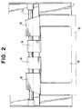
- Figure 2 is a schematic plan view of a bill counting apparatus including a bill feeding apparatus which is an embodiment of the present invention.
- Figure 3 is a schematic cross-sectional view taken along a line A-A in Figure 1.
- a bill feeding apparatus for a bill counting apparatus which is an embodiment of the present invention, comprises a bill stacking plate 1 on which bills B to be counted are stacked, a front plate 3 for forming a gap 2 for feeding out the bills B between the bill stacking plate 1 and itself, feed-out rollers 5 which are provided so as to partly project upwardly from an opening 4 formed in the bill stacking plate 1 and are rotated so as to feed the bills stacked on the bill stacking plate 1 into the bill counting apparatus via the gap 2, take-out rollers 6 which are rotated in synchronism with the feed-out rollers 5 for further feeding the bills B fed out from the bill stacking plate 1 by the feed-out rollers 5 into the bill counting apparatus, and separation rollers 7 which cooperate with the take-out rollers 6 for preventing two or more bills B from being fed into the bill counting apparatus simultaneously.
- the separation rollers 7 are held stationary and at least periphery thereof facing the take-out rollers 6 is formed with a friction portion
- the bill counting apparatus is constituted so as to feed two kinds of bills B which differ in width into the bill counting apparatus.
- the bill counting apparatus is provided with a pair of first guides 8 for restricting the lateral position of the bills B of the denomination having wider width and a pair of second guides 9 for restricting the lateral position of the bills B of the denomination having narrower width.
- the pair of first guides 8 are mounted rotatably and slidably in the widthwise direction on a shaft 10 so that the distance therebetween can be adjusted in accordance with the width of the bills of the denomination having wider width to be guided and the front edge portions thereof can abut against the rear surface of the front plate 3.
- the first guides 8 are held in such a manner that the front edge portions thereof abut against the rear surface of the front plate 3, they are formed so that the lower edge portions thereof can be positioned lower than the lowermost bill B among the wider bills B lifted by the feed-out rollers 5 which are provided so as to partly project from the opening 4 formed in the bill stacking plate 1.
- the pair of second guides 9 are mounted rotatably and slidably along the shaft 10 on the shaft 10 so that the distance therebetween can be adjusted in accordance with the width of the narrower bills B and the lower edge portions thereof abut against the upper surface of the uppermost bill B of the denomination having wider width by the dead weight thereof.
- a pair of endless belts 13, 14 are respectively wound around pulleys 11, 12 in the bill counting apparatus downstream of the take-out rollers 6, thereby forming a bill transporting portion 15.
- the bills B fed into the bill counting apparatus by the take-out rollers 6 are further fed into the bill counting apparatus while they are being held by the pair of endless belts 13, 14.
- the bill transporting portion 15 is provided-with an optical sensor 16 and a magnetic sensor 17 for discriminating denominations of the bills B and whether or not the bills B are acceptable and counting the number of the bills B.
- the bills B are set on the bill stacking plate 1 so that the bills B of the denomination having wider width are stacked in a lower position and that the bills B of the denomination having narrower width are stacked in a upper position.
- the first guides 8 are slid along the shaft 10 until they come into abutment against opposite side portions of the bills B of the denomination having wider width and the front edge portions thereof are caused to abut against the rear surface of the front plate 3 where they are held.
- the second guides 9 are slid along the shaft 10 until they come into abutment against opposite side portions of the bills B of the denomination having narrower width and they are caused to contact the uppermost bill B of the denomination having wider width by the dead weight thereof and are held at that position.
- the stationary separation rollers 7 apply a friction force whose direction is opposite to the transporting direction of bills B to the upper surface of the bill B, even if two or more bills B have been simultaneously fed out by the feed-out rollers 5, they are separated into individual bills B and, therefore, two or more overlapped bills B are prevented from being fed into the bill counting apparatus.
- the bill B of the denomination having wider width fed into the bill counting apparatus by the feed-out rollers 5 and take-out rollers 6 in this manner is fed to the bill transporting portion 15 and is further fed downstream in the bill counting apparatus while they are being held by the pair of endless belts 13, 14.
- the optical sensor 16 and the magnetic sensor 17 discriminate the denomination of the bill B and whether or not the bill B is acceptable and count the bill B.
- the lateral position of the bill B of the denomination having wider width is restricted by the pair of first guides 8 when it is fed out by the feed-out rollers 5, the bill B is fed into the bill counting apparatus along a desired path. Therefore, it is possible to prevent the optical sensor 16 and the magnetic sensor 17 from erroneously discriminating and counting the bill B because the bill B of the denomination having wider width has deviated from the desired path and passed through the wrong portion of the optical sensor 16 and the magnetic sensor 17.
- the pair of second guides 9 Since the distance between a pair of second guides 9 is determined in such a manner that they abut against the opposite side portions of the bills B of the denomination having narrower width and the lower edge portions thereof contact the upper surface of the uppermost bill B among the bills B of the denomination having wider width by the dead weight thereof, each time a bill B of the denomination having wider width is fed, the pair of second guides 9 is lowered while maintaining contact with the upper surface of the uppermost bill B of the denomination having wider width and continues to restrict the lateral position of the bills B of the denomination having narrower width during the time period when the bills B of the denomination having wider width are being fed into the bill counting apparatus.
- the pair of second guides 9 comes into contact with the upper surface of the bill stacking plate 1. Thereafter, the pair of second guides 9 restricts the lateral position of the bills B of the denomination having narrower width while maintaining contact with the upper surface of the bill stacking plate 1.
- the narrower bills B are fed into the bill counting apparatus along a desired path and are prevented from deviating from the desired path, it is possible to accurately discriminate the denominations of the bills B and whether or not the bills B are acceptable and to accurately count the number of the bills B by the optical sensor 16 and the magnetic sensor 17.
- the pair of second guides 9 which abuts against the opposite side portions of the bills B of the denomination having narrower width and maintains their lower edge portions in contact with the upper surface of the uppermost bill B among the bills B of the denomination having wider width by the dead weight thereof, even if vibration or the like acts on the bills B of the denomination having narrower width during the time period when the bills B of the denomination having wider width are being fed into the bill counting apparatus by the feed-out rollers 5 and the take-out rollers 6 rotated in synchronism with each other, the lateral position of the bills B of the denomination having narrower width is always restricted by the pair of second guides 9.
- the bills B of the denomination having narrower width stacked on the bills B of the denomination having wider width can be fed into the bill counting apparatus along a desired path and it is possible to accurately discriminate the denominations of the narrower bills B and whether or not they are acceptable and accurately count the number of the narrower bills B by the optical sensor 16 and the magnetic sensor 17.
- the bill feeding apparatus is constituted so as to feed two kinds of bills B of different width into the bill counting apparatus
- the present invention can be applied to a bill feeding apparatus for feeding three or more kinds of bills B of different width in the direction perpendicular to the feeding direction.
- an additional pair of guides is be provided for each denomination of bills B other than the denomination of the widest bills B so that each pair of the guides abuts against the opposite side portions of the corresponding denomination of bills B so as to be able to restrict the lateral position thereof and contacts the upper surface of the uppermost bill B among the denomination of bills B stacked immediately beneath the corresponding denomination of bills B by the dead weight thereof.
- the first guides 8 are formed so that the lower edge portions thereof are positioned lower than the lowermost bill B among the wider bills B lifted by the feed-out rollers 5 provided so as to partly project from the opening 4 formed in the bill stacking plate 1 when the front edge portions thereof abut against the rear surface of the front plate 3 and is held there.
- the first guides 8 may be disposed so as to abut against the upper surface of the bill stacking plate 1.
- the second guides 9 are constituted so as to be able to contact the upper surface of the uppermost bill B among the bills B of the denomination having wider width by the dead weight thereof, if the bills B of the denomination having wider width can be fed into the bill counting apparatus through the gap 2 by the rotation of the feed-out rollers 5, they may abut the upper surface of the uppermost bill B among the bills B of the denomination having wider width by a biasing means such as a spring.
- a biasing means such as a spring.
- separation rollers 7 are held stationary in the above described embodiment, the separation rollers 7 may be rotated in the same direction as the take-out rollers 6.
- the present invention can be applied to bill feeding apparatuses for all type of bill handling machines.
- the present invention can be preferably applied to an apparatus such as a bill feeding apparatus for a bill counting apparatus in which sheets are fed at high speed
- the present invention can be widely applied to any sheet feeding apparatus such as for a facsimile machine or a copying machine in which a plurality of sheets of different widths in the direction perpendicular to the feeding direction may be set together and fed.
Landscapes
- Engineering & Computer Science (AREA)
- Mechanical Engineering (AREA)
- Sheets, Magazines, And Separation Thereof (AREA)
- Fish Paste Products (AREA)
- Formation And Processing Of Food Products (AREA)
- Belt Conveyors (AREA)
Claims (6)
- Appareil d'alimentation de feuilles comprenant une portion (1) d'empilage de feuilles sur laquelle une pluralité de feuilles (B) de largeur de feuille différente dans une direction d'alimentation de feuille est disposée par empilage des feuilles dans l'ordre des feuilles les plus larges de sorte que les feuilles les plus larges soient disposées dans la position la plus basse et adapté à alimenter dos feuilles avec une position latérale des feuilles la plus larges limitée le long d'un chemin désiré par une paire de moyens de guidage ménagés dans la portion d'empilage de feuille, caractérisé en ce que ledit appareil d'alimentation de feuilles comprend en outre une paire ou des paires de moyens de guidage de feuille (8,9) en un nombre qui n'est pas inférieur au nombre de sortes de feuilles (B) dont la largeur diffère de la plus grande largeur, chaque paire de moyens de guidage de feuille étant adaptée à limiter la position latérale des feuilles ayant la largeur correspondante le long d'un chemin désiré et à toujours être en contact avec une surface supérieure des feuilles disposées immédiatement en dessous des feuilles ayant la largeur correspondante.
- Appareil d'alimentation de feuilles selon la revendication 1, dans lequel la paire de moyens de guidage est adaptée à limiter la position latérale des feuilles les plus larges en venant buter contre les côtés opposés des feuilles les plus larges et chaque paire de moyens de guidage de feuille est adaptée à limiter la position latérale des feuilles ayant la largeur correspondante en venant buter contre les côtés opposé de celles-ci.
- Appareil d'alimentation de feuilles selon la revendication 1 ou 2, dans lequel chaque paire de moyens de guidage de feuille est adaptée à toujours être en contact avec une surface supérieure des feuilles disposées immédiatement en dessous des feuilles ayant la largeur correspondante à l'aide de leur poids propre.
- Appareil d'alimentation de billets comprenant une portion (1) d'empilage de billets sur laquelle une pluralité de billets (B) de largeur de billet différente dans une direction d'alimentation de billet est disposée par empilage des billets dans l'ordre des billets les plus larges de sorte que les billets les plus larges sont disposés dans la position la plus basse et adapté à alimenter les billets avec une position latérale des billets les plus larges limitée le long d'un chemin désiré par une paire de moyens de guidage ménagés dans la portion d'empilage de billets, caractérisé en ce que ledit appareil d'alimentation de billets comprend en outre une paire ou des paires de moyens de guidage de billet (8,9) en un nombre qui n'est pas inférieur au nombre de sortes de feuilles (B) dont la largeur diffère de la plus grande largeur, chaque paire de moyens de guidage de billet étant adaptée à limiter la position latérale des billets ayant la largeur correspondante le long d'un chemin désiré et à toujours être en contact avec une surface supérieure des billets disposés immédiatement en dessous des billets ayant la largeur correspondante.
- Appareil d'alimentation de billets selon la revendication 4, dans lequel la paire de moyens de guidage est adaptée à limiter la position latérale des billets la plus larges en venant buter contre les côtés opposés des billets les plus larges et chaque paire des moyens de guidage de billet est adaptée à limiter la position latérale des billets ayant la largeur correspondante en venant en butée contre les côtés opposés de celui-ci.
- Appareil d'alimentation de billets selon la revendication 4, dans lequel chaque paire des moyens de guidage de billet est adaptée à toujours être en contact avec une surface supérieure des billets disposée Immédiatement en dessous des billets ayant la largeur correspondante à l'aide de leur poids propre.
Applications Claiming Priority (2)
| Application Number | Priority Date | Filing Date | Title |
|---|---|---|---|
| JP4231782A JP2725118B2 (ja) | 1992-08-31 | 1992-08-31 | シート供給装置 |
| JP231782/92 | 1992-08-31 |
Publications (2)
| Publication Number | Publication Date |
|---|---|
| EP0590285A1 EP0590285A1 (fr) | 1994-04-06 |
| EP0590285B1 true EP0590285B1 (fr) | 1996-05-15 |
Family
ID=16928950
Family Applications (1)
| Application Number | Title | Priority Date | Filing Date |
|---|---|---|---|
| EP93113026A Expired - Lifetime EP0590285B1 (fr) | 1992-08-31 | 1993-08-13 | Dispositif d'alimentation de feuilles |
Country Status (6)
| Country | Link |
|---|---|
| US (1) | US5350165A (fr) |
| EP (1) | EP0590285B1 (fr) |
| JP (1) | JP2725118B2 (fr) |
| KR (1) | KR0131440B1 (fr) |
| AT (1) | ATE138042T1 (fr) |
| DE (1) | DE69302649T2 (fr) |
Families Citing this family (8)
| Publication number | Priority date | Publication date | Assignee | Title |
|---|---|---|---|---|
| US5927705A (en) * | 1997-05-07 | 1999-07-27 | Lexmark International, Inc. | Envelope feeder |
| US5927708A (en) * | 1997-12-19 | 1999-07-27 | Pitney Bowes Inc. | Adjustable side guide for mail processing machines |
| JP4281085B2 (ja) * | 2003-05-21 | 2009-06-17 | 株式会社日本コンラックス | 紙幣処理装置 |
| FR2859195B1 (fr) * | 2003-08-25 | 2005-11-25 | Neopost Ind | Dispositif anti-biais pour machine de traitement de courrier |
| KR20050105730A (ko) * | 2004-05-03 | 2005-11-08 | 엘지전자 주식회사 | 드럼세탁기 및 그 제어방법 |
| US7255342B2 (en) | 2004-08-05 | 2007-08-14 | Neopost Industrie | Anti-skew device for mail processing machine |
| JP7057272B2 (ja) * | 2018-12-19 | 2022-04-19 | 株式会社ユニバーサルエンターテインメント | 紙葉類処理システム、及び、紙葉類処理装置 |
| CN110599675B (zh) * | 2019-08-26 | 2021-08-13 | 深圳市合众金融设备服务有限公司 | 钞箱纸币数量的检测方法、装置、终端设备和存储介质 |
Family Cites Families (7)
| Publication number | Priority date | Publication date | Assignee | Title |
|---|---|---|---|---|
| CH526818A (de) * | 1970-10-14 | 1972-08-15 | Kienzle Apparate Gmbh | Einrichtung zur Zuführung und Ausrichtung von Belegen zu bzw. in einer Druckstation |
| JPS5969322A (ja) * | 1982-10-13 | 1984-04-19 | Fuji Xerox Co Ltd | 給紙カセツト |
| US4714243A (en) * | 1986-01-28 | 1987-12-22 | Ziyad Incorporated | Paper tray for a printing device |
| US4838535A (en) * | 1986-02-06 | 1989-06-13 | Brother Kogyo Kabushiki Kaisha | Sheet feeding device with detachable holder means for thick cut sheets |
| US4786044A (en) * | 1987-03-06 | 1988-11-22 | General Electric Company | Insert for adjustable sheet guide |
| JPH03162345A (ja) * | 1989-11-22 | 1991-07-12 | Minolta Camera Co Ltd | シート給送装置 |
| US5085419A (en) * | 1991-01-30 | 1992-02-04 | Xerox Corporation | Paper feeder insert tray |
-
1992
- 1992-08-31 JP JP4231782A patent/JP2725118B2/ja not_active Expired - Lifetime
-
1993
- 1993-08-12 US US08/105,055 patent/US5350165A/en not_active Expired - Fee Related
- 1993-08-13 AT AT93113026T patent/ATE138042T1/de active
- 1993-08-13 EP EP93113026A patent/EP0590285B1/fr not_active Expired - Lifetime
- 1993-08-13 DE DE69302649T patent/DE69302649T2/de not_active Expired - Lifetime
- 1993-08-24 KR KR1019930016441A patent/KR0131440B1/ko not_active Expired - Lifetime
Also Published As
| Publication number | Publication date |
|---|---|
| EP0590285A1 (fr) | 1994-04-06 |
| DE69302649D1 (de) | 1996-06-20 |
| DE69302649T2 (de) | 1996-09-26 |
| JPH0672571A (ja) | 1994-03-15 |
| US5350165A (en) | 1994-09-27 |
| KR940003823A (ko) | 1994-03-12 |
| JP2725118B2 (ja) | 1998-03-09 |
| ATE138042T1 (de) | 1996-06-15 |
| KR0131440B1 (ko) | 1998-04-11 |
Similar Documents
| Publication | Publication Date | Title |
|---|---|---|
| US5236072A (en) | Document size detection device | |
| US8006972B2 (en) | Paper sheet processing apparatus | |
| JP6360307B2 (ja) | シート給送装置、原稿給送装置、画像読取装置 | |
| JPH06298403A (ja) | 紙葉類搬送装置 | |
| EP0590285B1 (fr) | Dispositif d'alimentation de feuilles | |
| EP0146391B1 (fr) | Appareil pour enlever des liens | |
| JP3432860B2 (ja) | 紙葉類のスキュー制御搬送装置 | |
| EP1746546B1 (fr) | Appareil d'alimentation pour billets de banque | |
| GB1303165A (fr) | ||
| GB2198122A (en) | Sheet store loading apparatus | |
| EP1211207A2 (fr) | Méthode et dispositif pour le traitement d'un matériau du type papier | |
| US5139149A (en) | Apparatus for stacking sheets | |
| JP6612308B2 (ja) | シート給送装置及び画像読取装置 | |
| JPS6248272B2 (fr) | ||
| JPH06305606A (ja) | 搬送装置 | |
| JPH0323465B2 (fr) | ||
| JP3243042B2 (ja) | 搬送装置 | |
| JPH06342487A (ja) | 紙葉類計数装置 | |
| JP2020035499A (ja) | 紙葉類処理装置 | |
| JP7595697B2 (ja) | シート給送装置及び画像読取装置 | |
| JPH05147749A (ja) | 紙葉類繰出し機構 | |
| JPH04303347A (ja) | シート搬送装置 | |
| JP2692258B2 (ja) | 紙葉類集積装置 | |
| JP2577779B2 (ja) | 紙葉類区分方法 | |
| JP2665098B2 (ja) | 紙葉類処理装置 |
Legal Events
| Date | Code | Title | Description |
|---|---|---|---|
| PUAI | Public reference made under article 153(3) epc to a published international application that has entered the european phase |
Free format text: ORIGINAL CODE: 0009012 |
|
| AK | Designated contracting states |
Kind code of ref document: A1 Designated state(s): AT DE FR GB IT NL SE |
|
| 17P | Request for examination filed |
Effective date: 19940609 |
|
| 17Q | First examination report despatched |
Effective date: 19950921 |
|
| GRAH | Despatch of communication of intention to grant a patent |
Free format text: ORIGINAL CODE: EPIDOS IGRA |
|
| GRAA | (expected) grant |
Free format text: ORIGINAL CODE: 0009210 |
|
| ITF | It: translation for a ep patent filed | ||
| AK | Designated contracting states |
Kind code of ref document: B1 Designated state(s): AT DE FR GB IT NL SE |
|
| REF | Corresponds to: |
Ref document number: 138042 Country of ref document: AT Date of ref document: 19960615 Kind code of ref document: T |
|
| REF | Corresponds to: |
Ref document number: 69302649 Country of ref document: DE Date of ref document: 19960620 |
|
| ET | Fr: translation filed | ||
| PLBE | No opposition filed within time limit |
Free format text: ORIGINAL CODE: 0009261 |
|
| 26N | No opposition filed | ||
| REG | Reference to a national code |
Ref country code: GB Ref legal event code: IF02 |
|
| PGFP | Annual fee paid to national office [announced via postgrant information from national office to epo] |
Ref country code: FR Payment date: 20110420 Year of fee payment: 19 |
|
| PGFP | Annual fee paid to national office [announced via postgrant information from national office to epo] |
Ref country code: NL Payment date: 20110428 Year of fee payment: 19 |
|
| PGFP | Annual fee paid to national office [announced via postgrant information from national office to epo] |
Ref country code: IT Payment date: 20110506 Year of fee payment: 19 |
|
| PGFP | Annual fee paid to national office [announced via postgrant information from national office to epo] |
Ref country code: DE Payment date: 20110829 Year of fee payment: 19 Ref country code: AT Payment date: 20110630 Year of fee payment: 19 Ref country code: SE Payment date: 20110811 Year of fee payment: 19 Ref country code: GB Payment date: 20110825 Year of fee payment: 19 |
|
| REG | Reference to a national code |
Ref country code: NL Ref legal event code: V1 Effective date: 20130301 |
|
| REG | Reference to a national code |
Ref country code: SE Ref legal event code: EUG |
|
| REG | Reference to a national code |
Ref country code: AT Ref legal event code: MM01 Ref document number: 138042 Country of ref document: AT Kind code of ref document: T Effective date: 20120813 |
|
| GBPC | Gb: european patent ceased through non-payment of renewal fee |
Effective date: 20120813 |
|
| PG25 | Lapsed in a contracting state [announced via postgrant information from national office to epo] |
Ref country code: SE Free format text: LAPSE BECAUSE OF NON-PAYMENT OF DUE FEES Effective date: 20120814 Ref country code: NL Free format text: LAPSE BECAUSE OF NON-PAYMENT OF DUE FEES Effective date: 20130301 |
|
| REG | Reference to a national code |
Ref country code: FR Ref legal event code: ST Effective date: 20130430 |
|
| PG25 | Lapsed in a contracting state [announced via postgrant information from national office to epo] |
Ref country code: IT Free format text: LAPSE BECAUSE OF NON-PAYMENT OF DUE FEES Effective date: 20120813 |
|
| PG25 | Lapsed in a contracting state [announced via postgrant information from national office to epo] |
Ref country code: AT Free format text: LAPSE BECAUSE OF NON-PAYMENT OF DUE FEES Effective date: 20120813 |
|
| PG25 | Lapsed in a contracting state [announced via postgrant information from national office to epo] |
Ref country code: GB Free format text: LAPSE BECAUSE OF NON-PAYMENT OF DUE FEES Effective date: 20120813 Ref country code: DE Free format text: LAPSE BECAUSE OF NON-PAYMENT OF DUE FEES Effective date: 20130301 |
|
| PG25 | Lapsed in a contracting state [announced via postgrant information from national office to epo] |
Ref country code: FR Free format text: LAPSE BECAUSE OF NON-PAYMENT OF DUE FEES Effective date: 20120831 |
|
| REG | Reference to a national code |
Ref country code: DE Ref legal event code: R119 Ref document number: 69302649 Country of ref document: DE Effective date: 20130301 |