EP0590298B1 - Procédé pour la synchronisation d'un récepteur pour la réception d'un signal de données qui sont étalées avec un code pseudo aléatoire - Google Patents
Procédé pour la synchronisation d'un récepteur pour la réception d'un signal de données qui sont étalées avec un code pseudo aléatoire Download PDFInfo
- Publication number
- EP0590298B1 EP0590298B1 EP93113446A EP93113446A EP0590298B1 EP 0590298 B1 EP0590298 B1 EP 0590298B1 EP 93113446 A EP93113446 A EP 93113446A EP 93113446 A EP93113446 A EP 93113446A EP 0590298 B1 EP0590298 B1 EP 0590298B1
- Authority
- EP
- European Patent Office
- Prior art keywords
- code
- signal
- correlation
- signals
- phase
- Prior art date
- Legal status (The legal status is an assumption and is not a legal conclusion. Google has not performed a legal analysis and makes no representation as to the accuracy of the status listed.)
- Expired - Lifetime
Links
Images




Classifications
-
- H—ELECTRICITY
- H04—ELECTRIC COMMUNICATION TECHNIQUE
- H04B—TRANSMISSION
- H04B1/00—Details of transmission systems, not covered by a single one of groups H04B3/00 - H04B13/00; Details of transmission systems not characterised by the medium used for transmission
- H04B1/69—Spread spectrum techniques
- H04B1/707—Spread spectrum techniques using direct sequence modulation
- H04B1/7073—Synchronisation aspects
- H04B1/7085—Synchronisation aspects using a code tracking loop, e.g. a delay-locked loop
Definitions
- the invention relates to a method for synchronization a receiver circuit for a received signal, which contains a data signal spread with a PN code, in which on the basis of an adjustable timer at least three PN code signals offset in time be generated, with a medium PN code signal with the received signal for data demodulation and a leading and trailing PN code signal for control purposes of the timer can be correlated with the received signal.
- PN "pseudo noise”
- the bandwidth of the PN signal is much larger than that of the message signal, the latter is spectrally spread. This requires considerable effort on the receiver side to synchronize the PN code in order to undo the spectral broadening.
- the PN code (receiver code) generated locally in the receiver must match the PN code of the received signal (transmitter code) more precisely than 1 code chip (duration T c ).
- the receiver synchronization is carried out by two process stages connected in series, namely the coarse synchronization ("acquisition") and the fine synchronization ("tracking").
- Such non-linear control loops have the property that they can lose synchronism under interference (Disengaging phenomenon).
- One way to snap this out prevent or increase the time until it disengages consists in the broadening of usually two correlation signals formed discriminator characteristic (Control characteristic, also called S-curve) with the help of additional ones Correlators.
- Control characteristic also called S-curve
- additional ones Correlators So z. B. from DE 37 43 731 Fine synchronization method with widened discriminator characteristic known. For this purpose, many are out of phase Code signals generated, all with the incoming Data signal are correlated. From the resulting Correlation curves become a by appropriate weighting Characteristic curve generated with an enlarged linear range. Because of of the additional correlators takes place in the synchronization circuit but the influence of channel noise while the useful signal contributions remain the same. In addition, the Greater effort for realization.
- the object of the invention is a method of the aforementioned Specify a type that improves synchronization behavior, especially tracking in a large one Control range allowed.
- the solution is that with one temporal drift of the data signal forward respectively. backwards on through the leading and trailing PN code signal defined control range adaptively shifted is by the trailing resp. the leading PN code signal by a predetermined time interval to the front resp. is moved to the rearmost position and reassigned the PN code sequences the data signal for data demodulation correlated with the PN code signal, which is now temporally mean becomes.
- the core of a PN code tracking loop according to the invention is that with increasing synchronization errors (Drift) individual correlation arms switched, d. H. on a different code position will be moved. This creates a periodic and piecewise linear discriminator characteristic.
- the advantage over the classic control loops e.g. DLL
- a narrow band control loop with a low-order loop filter in principle fast dynamic processes by switching individual correlation arms can readjust.
- a narrow-band classic tracking loop with the same Loop filter not a fast changing input signal can follow and bass out.
- Correlators necessary.
- exactly three PN code signals offset by deltaT c are generated.
- the previous resp. later PN code signal by 3 deltaT c to the front resp. last position moved is covered with only three correlators.
- the switching criterion is advantageously chosen such that there is always a switching hysteresis. This makes an all too frequent switching avoided. It will also be an advantage paid attention to the performance of the correlation signal in the data path (i.e. in the path that is used for data demodulation a certain percentage (related to the maximum possible correlation performance).
- a Moving the control range whenever the performance of the correlation signal in the correlation path is smaller than that Is half that of a rule path. This can help the advantageous switching hysteresis can be achieved in a simple manner.
- a synchronization circuit is a switching matrix with which optionally two adaptively definable signal paths to the control circuit and one passed to a data modulation circuit can be.
- the PN code generator is designed that the phase position of each PN code signal output at the outputs can be shifted in phase by predetermined intervals is. This can be done e.g. B. with controllable resp. implement programmable delay elements.
- the inventive method is particularly suitable for Synchronize cellular receivers. With these shifts the received signal depends on the relative speed towards the broadcaster.
- a received signal r (t) to three essentially identical in terms of circuitry Correlation paths split.
- the received signal r (t) with a PN code signal correlated defined phase position.
- Bandpass filter 2.1 respectively 2.2 resp. 2.3 becomes the output signal the mixer 1.1 respectively.
- 1.2 resp. 1.3 in itself filtered in a known manner and then on the one hand via a line 4.1 resp. 4.2 resp. 4.3 direct synchronization control 5 and on the other hand an envelope detector 3.1 resp. 3.2 resp. 3.3 fed.
- the envelope detectors 3.1, 3.2, 3.3 form z. B. the absolute amount of the input signal or the amplitude square.
- the one with the envelope detectors 3.1, 3.2, 3.3 generated data-neutral correlation signals are also fed to the synchronization controller 5.
- the synchronization controller 5 represents the heart of the switching arrangement according to the invention. It outputs an (despread) signal for data demodulation at an output 6, from which the transmitted data are extracted by means of a demodulation circuit (not shown). An error signal e (t) is output at an output 7 and is fed to a VCO 9 via a circular filter 8.
- This VCO 9 represents the timer for a PN code generator 10 which, according to the invention, can generate identical PN code signals at three outputs 11.1, 11.2, 11.3 except for the phase position.
- the phase position of each PN code signal can be varied within a predetermined time grid.
- the time grid is defined by a time difference deltaT c .
- the synchronization controller 5 also gives the circular filter 8 the important in the switching described below Initial conditions. Finally, it gives to the PN code generator 10 the code positions respectively. Phases for the PN signals continue.
- Hint is one for any heterodyne The necessary expansion of the circuit is drawn in. It is a local oscillator 12 and a multiplier / mixer 13.1, 13.2, 13.3 for each PN code signals output at outputs 11.1, 11.2, 11.3.
- the functioning of the synchronization controller 5 will be explained with reference to FIGS. 2a-e. It is assumed that three PN code signals are shifted at the outputs 11.1, 11.2, 11.3 by deltaT c in time.
- the (phase-wise) mean PN code signal which e.g. B. at the output 11.2 and correlated in the mixer 1.2 with the received signal r (t), in particular the controllable timer (VCO 9) tracks the received signal r (t) as well as possible by means of the synchronization circuit.
- a characteristic curve 17.1 is obtained, which in principle allows a control range of width 2 (T c + deltaT c ) (characteristic curve 17.1 disappears outside this range).
- the error signal for tracking the VCO 9 has an amplitude which follows from the characteristic curve 17.1 in accordance with the synchronization error epsilon.
- the data demodulation is carried out on the basis of the middle correlation curve 15. Under normal circumstances, ie when there is no drift in the phase position of the received signal, the synchronization circuit according to the invention operates on the principle of a conventional DLL. However, if the received signal shifts so much in phase that the power according to correlation curve 15 is lower than in correlation curve 14 or 16, the switchover described below is carried out.
- the correlation paths are reassigned in the sense that the data demodulation is carried out on the basis of the now (phase-wise) mean correlation curve 16.
- the difference between the correlation curve 19 and the formerly mean correlation curve 15 is used to generate the error signal (cf. FIG. 2d).
- a comparison of the two FIGS. 2b and d shows that the time-shifted characteristic curve 17.2 has taken the place of the characteristic curve 17.1.
- the control is now also carried out on another zero point (which is also shifted by deltaT c ).
- the whole switching process described above is from the Synchronization control 5 performed. She tests the Correlation values in the three paths determine the necessary ones
- the individual PN code signals are shifted Initial condition for the output signal of the circular filter 8 and changes the assignment between the over the lines 4.1, 4.2, 4.3 fed correlation signals and the output 6.
- a switchover criterion which is particularly preferred is leads to a hysteresis of the discriminator characteristic.
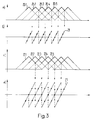
- An example for a switchover with hysteresis is from Fig. 3c and d. In this example, we always switch over if the performance in the leading or trailing Path is twice the size of the middle one. Because of the smaller distance between the correlation curves 22.1, ..., 22.5 (compared to Fig. 2), the preferred, means Arrows indicated hysteresis in the discriminator characteristic 23. It should be noted that ideally when switching the phase error disappears because the new "rest position" with the "limit point" of the characteristic which has not yet been switched over coincides.
- Hysteresis can be done with a variety of means bring about. So z. B. also more than three correlation paths are provided, with a switching by Monitoring the signal power in the different correlation paths and switching the path of maximum power be improved for data demodulation. At four or five parallel correlation paths is not just one middle path available and a switch respectively. Move the control range can be postponed longer, without the performance in the demodulation path being too small becomes. For example, there are five correlation paths three middle paths, optionally based on the maximum criterion Performance can be used for data demodulation can. As long as the received signal is not in the range of earliest resp. latest correlation signal runs in namely, no phase shifts are required.
- Fig. 4 shows a block diagram of the synchronization control 5.
- a switching matrix 24 is designed so that of control signals of the changeover control 29 optionally one of the adjoining inputs 26.1, 26.2, 26.3 Signals containing data on the output 27.1 purpose Data demodulation can be switched.
- the envelopes of the Signals are sent to inputs 30.1, 30.2, 30.3 of the switchover control 29 fed. This leads with the aid of FIGS. 2a-e and 3a-d explained tests and determined the reallocation the correlation paths, the initial conditions for the Circular filter 8 (output 32) and the code position resp. Phase position for the PN code generator 10 (output 31).
- the switching matrix 24 also has inputs 25.1, 25.2, 25.3 for the data-neutral output signals of the envelope detectors 3.1, 3.2, 3.3 (see Fig. 1). Two of these three entrances are in accordance with the control signals of the switching control 29 given to outputs 27.2 and 27.3. A subtractor 28 forms the difference and gives it as an error signal (Input signal of the circular filter 8).
- FIG. 5 finally shows a block diagram of a synchronization control for synchronization according to the principle of the MCTL (Modified Code Tracking Loop).
- a switching matrix 33 At the entrances 34.1, 34.2, 34.3 of a switching matrix 33 are the data carriers Correlation signals (see lines 4.1, 4.2, 4.3 in Fig. 1).
- the input signals mentioned are corresponding the signals of a switching control 41 optionally the outputs 35, 36, 37 out.
- the output 35 is for the Data demodulation used.
- the outputs 36 and 37 are subtracted from each other in a subtractor 38.
- the resulting one Difference is in a multiplier 39 by multiplied signal output at the output 35. This results at an output 40 the error signal, which via a Circular filter is given to a VCO.
- the invention is also based on other known control structures applicable.
- a structure is e.g. B. the known tau dither loop. Similar to what happens with the DLL in the tau dither loop by the invention a periodic Discriminator characteristic generated. The same applies to the so-called double dither loop.
- the new PN code tracking loop it is thus possible with three shifted and adaptively switchable correlation paths a periodic Generate discriminator characteristic.
- the circuit concept according to the invention can also be used for coarse synchronization and leads to a significant acceleration. Because all three Correlation arms are constructed identically and a performance measurement Coarse synchronization is possible in all arms about three times faster than with a synchronization circuit in which only one correlation path is available for a performance measurement.
Landscapes
- Engineering & Computer Science (AREA)
- Computer Networks & Wireless Communication (AREA)
- Signal Processing (AREA)
- Synchronisation In Digital Transmission Systems (AREA)
Claims (8)
- Procédé pour synchroniser un circuit de réception sur un signal de réception, qui contient un signal de donnée étalé avec un code PN, selon lequel au moins trois signaux de code PN réciproquement décalés dans le temps sont produits sur la base d'une minuterie réglable, un signal de code PN centré dans le temps est corrélé, dans une première voie de corrélation, au signal de réception pour la démodulation des données, et un signal de code PN en avance dans une seconde voie de corrélation et un signal de code PN en retard dans une troisième voie de corrélation sont corrélés au signal de réception pour réaliser la régulation de la minuterie, caractérisé en ce que dans le cas d'une dérive dans le temps du signal de donnée dans le sens de l'avance ou dans le sens rétrograde, une plage de régulation définie par le signal de code PN, qui est en avance, et par le signal de code PN, qui est en retard, est décalée de façon adaptative par le fait que le signal de code PN, qui est en retard, ou le signal de code PN, qui est en avance, est décalé d'un intervalle de temps prédéterminé en direction de la position la plus en avant ou de la position la plus en arrière et qu'une démodulation de données est exécutée avec le signal de code PN, qui est maintenant centré, moyennant une nouvelle association des signaux de code PN.
- Procédé selon la revendication 1, caractérisé en ce que précisément trois signaux de code PN, qui sont décalés respectivement de deltaTc sont produits et que dans le cas du déplacement adaptatif de la plage de régulation, le signal de code PN, qui est en avance, ou le signal de code PN, qui est en retard, est décalé de 3 deltaTc pour être amené à l'emplacement le plus en arrière ou à l'emplacement le plus en avant.
- Procédé selon la revendication 1 ou 2, caractérisé en ce qu'on choisit delta = 0,5.
- Procédé selon la revendication 1 ou 2, caractérisé en ce qu'on choisit delta = 1.
- Procédé selon l'une des revendications 1 à 4, caractérisé en ce qu'un décalage de la plage de réglage est exécuté chaque fois que la puissance dans la voie centrale de corrélation est plus faible que dans l'une des voies de corrélation les plus extérieures.
- Procédé selon l'une des revendications 1 à 4, caractérisé en ce que le décalage de la plage de régulation est exécuté chaque fois que la puissance de la voie centrale de corrélation est inférieure à la moitié de la puissance dans l'une des voies de corrélation les plus extérieures.
- Circuit de synchronisation comprenantcaractérisé en ce quea) une minuterie réglable (9),b) un générateur de code PN (10) comportant au moins trois sorties (11.1, 11.2, 11.3) servant à produit au moins trois signaux de code PN dont les phases sont réciproquement décalées,c) pour chaque sortie (11.1, 11.2, 11.3) du générateur de code PN (10), une voie de corrélation comportant un mélangeur (1.1, 1.2, 1.3) pour corréler le signal de réception (r(t)) avec respectivement l'un des signaux de code PN, et un circuit de transmission de signaux de régulation pour l'asservissement de la minuterie (9).
d) il est prévu une matrice de commutation (24), avec laquelle au choix deux voies de corrélation pouvant être fixées de façon adaptative peuvent être raccordées au circuit de régulation (8, 9) et à un circuit de démodulation, et que le générateur de code PN (10) est agencé de telle sorte que les positions de phase des différents signaux de code PN, délivrés sur les sorties (11.1, 11.2, 11.3) sont décalées d'intervalles prédéterminés. - Récepteur pour des signaux d'information à bande étalée, caractérisé par un circuit de synchronisation selon la revendication 7.
Applications Claiming Priority (2)
| Application Number | Priority Date | Filing Date | Title |
|---|---|---|---|
| CH304092 | 1992-09-29 | ||
| CH3040/92 | 1992-09-29 |
Publications (3)
| Publication Number | Publication Date |
|---|---|
| EP0590298A2 EP0590298A2 (fr) | 1994-04-06 |
| EP0590298A3 EP0590298A3 (en) | 1994-06-01 |
| EP0590298B1 true EP0590298B1 (fr) | 1998-04-15 |
Family
ID=4247274
Family Applications (1)
| Application Number | Title | Priority Date | Filing Date |
|---|---|---|---|
| EP93113446A Expired - Lifetime EP0590298B1 (fr) | 1992-09-29 | 1993-08-24 | Procédé pour la synchronisation d'un récepteur pour la réception d'un signal de données qui sont étalées avec un code pseudo aléatoire |
Country Status (3)
| Country | Link |
|---|---|
| US (1) | US5436935A (fr) |
| EP (1) | EP0590298B1 (fr) |
| DE (1) | DE59308402D1 (fr) |
Families Citing this family (19)
| Publication number | Priority date | Publication date | Assignee | Title |
|---|---|---|---|---|
| US6111911A (en) * | 1995-06-07 | 2000-08-29 | Sanconix, Inc | Direct sequence frequency ambiguity resolving receiver |
| US5600328A (en) * | 1995-06-21 | 1997-02-04 | Matsushita Electric Industrial Co., Ltd. | Demodulator circuit in global positioning system receiver |
| WO1997006446A2 (fr) * | 1995-08-09 | 1997-02-20 | Magellan Corporation | Reduction des erreurs par trajets multiples dans un recepteur a spectre etale pour mesures de distance |
| US5953367A (en) | 1995-08-09 | 1999-09-14 | Magellan Corporation | Spread spectrum receiver using a pseudo-random noise code for ranging applications in a way that reduces errors when a multipath signal is present |
| KR970078064A (ko) * | 1996-05-31 | 1997-12-12 | 배순훈 | 디지탈 디엘엘용 의사 잡음 발생 제어 장치 |
| US5805646A (en) * | 1996-10-08 | 1998-09-08 | Ericsson Inc. | Synchronization method, and associated circuitry, for improved synchronization of a receiver with a transmitter using early-late testing during coarse synchronization |
| US6237075B1 (en) * | 1998-03-10 | 2001-05-22 | Pan Atlantic Corporation | System and method for generating pseudo-random codes |
| US6079007A (en) * | 1998-03-10 | 2000-06-20 | Pan Atlantic Corporation | System and method for generating pseudo-random codes |
| US7224713B2 (en) * | 1998-04-09 | 2007-05-29 | Andrzej Partyka | Telemetry system with authentication |
| JP3825179B2 (ja) * | 1998-07-17 | 2006-09-20 | 富士通株式会社 | 相関器 |
| US6967974B1 (en) | 1999-09-30 | 2005-11-22 | Andrzej Partyka | Transmission of urgent messages in telemetry system |
| US6894975B1 (en) * | 2000-01-15 | 2005-05-17 | Andrzej Partyka | Synchronization and access of the nodes in a communications network |
| US6925105B1 (en) | 2000-05-01 | 2005-08-02 | Andrzej Partyka | Overhead reduction in system for intermittent transmission |
| KR100333818B1 (ko) * | 2000-08-16 | 2002-04-26 | 윤종용 | 디지털 오디오 수신기에서 널 심볼을 이용한 전송 모드검출 장치 및 방법 |
| US7209495B2 (en) | 2000-09-28 | 2007-04-24 | Andrzej Partyka | Urgent messages and power-up in frequency hopping system for intemittent transmission |
| US6834040B2 (en) * | 2001-02-15 | 2004-12-21 | Agilent Technologies, Inc. | Measurement synchronization method for voice over packet communication systems |
| ES2257923B1 (es) * | 2004-05-24 | 2007-07-01 | Universitat Politecnica De Catalunya | Receptor superregenerativo sincrono de altas prestaciones. |
| US10957445B2 (en) | 2017-10-05 | 2021-03-23 | Hill-Rom Services, Inc. | Caregiver and staff information system |
| US11496176B1 (en) * | 2020-06-23 | 2022-11-08 | Massive Light, LLC | Large instantaneous bandwidth radio frequency front-end for wireless systems |
Family Cites Families (6)
| Publication number | Priority date | Publication date | Assignee | Title |
|---|---|---|---|---|
| US4638494A (en) * | 1970-08-19 | 1987-01-20 | Sperry Corporation | System for the acquisition of code signals |
| US4203071A (en) * | 1978-08-08 | 1980-05-13 | The Charles Stark Draper Laboratory, Inc. | Pseudo-random-number-code-detection and tracking system |
| US4221005A (en) * | 1979-05-21 | 1980-09-02 | Nasa | Pseudonoise code tracking loop |
| US5090023A (en) * | 1986-09-29 | 1992-02-18 | Kabushiki Kaisha Kenwood | Spread spectrum communication system |
| DE3743732C2 (de) * | 1987-12-23 | 1994-12-01 | Ant Nachrichtentech | Verfahren zur Synchronisierung eines Codewortes mit einem empfangenen spektral gespreizten Signal |
| DE3743731C2 (de) * | 1987-12-23 | 1994-11-24 | Ant Nachrichtentech | Verfahren und Schaltungsanordnung zur Regelung der Phasenlage zwischen einem erzeugten Code und einem in einem empfangenen spektral gespreizten Signal enthaltenen empfangenen Code |
-
1993
- 1993-08-24 EP EP93113446A patent/EP0590298B1/fr not_active Expired - Lifetime
- 1993-08-24 DE DE59308402T patent/DE59308402D1/de not_active Expired - Fee Related
- 1993-09-13 US US08/119,546 patent/US5436935A/en not_active Expired - Fee Related
Also Published As
| Publication number | Publication date |
|---|---|
| EP0590298A3 (en) | 1994-06-01 |
| DE59308402D1 (de) | 1998-05-20 |
| EP0590298A2 (fr) | 1994-04-06 |
| US5436935A (en) | 1995-07-25 |
Similar Documents
| Publication | Publication Date | Title |
|---|---|---|
| EP0590298B1 (fr) | Procédé pour la synchronisation d'un récepteur pour la réception d'un signal de données qui sont étalées avec un code pseudo aléatoire | |
| DE68921265T2 (de) | Mehrfache Wiederverwendung eines FM-Bandes. | |
| DE69423039T2 (de) | Progressiver korrelationsdetektor | |
| DE69113038T2 (de) | Taktrückgewinnungsschaltung ohne anhebung des jitters. | |
| WO1991006164A1 (fr) | Recepteur numerique pour signaux d'etalement de bande | |
| DE69406151T2 (de) | Einrichtung zur Synchronisierung eines lokalen Trägers, in OFDM-Systemen | |
| DE69111632T2 (de) | GPS-Empfänger. | |
| DE3586255T2 (de) | Kommunikationssystem fuer bidirektionale digitalsignale. | |
| DE69007609T2 (de) | Kodeerfassungsverfahren und schaltung für spreizspektrumsignalempfänger. | |
| DE69500892T2 (de) | PLL-Synthetisierer | |
| DE69130718T3 (de) | Digitaler Synthesizer mit Phasenspeicher | |
| DE69924277T2 (de) | Verfahren und schaltung für die erzeugung einer variablen taktfrequenz | |
| DE3743732C2 (de) | Verfahren zur Synchronisierung eines Codewortes mit einem empfangenen spektral gespreizten Signal | |
| DE69300291T2 (de) | Frequenzregelschleife. | |
| DE3784694T2 (de) | Funkdatenuebertragungssystem. | |
| DE2048055C1 (de) | Verfahren zur Feststellung der | |
| DE3743731A1 (de) | Verfahren und schaltungsanordnung zur regelung der phasenlage zwischen einem erzeugten code und einem in einem empfangenen spektral gespreizten signal enthaltenen empfangenen code | |
| DE69030276T2 (de) | Frequenzsynthetisierer | |
| EP0590323A1 (fr) | Filtre pour le réglage de la largeur de bande d'une boucle de réglage | |
| DE60125764T2 (de) | Lineare digitale phasendetektion ohne toten bereich | |
| DE2623002B2 (de) | Konverter zur Umsetzung der Taktfrequenz digitaler Signale | |
| DE3028945C2 (de) | Abstimmeinrichtung mit phasensynchronisierter Schleife und Maßnahmen zur automatischen Feinabstimmung | |
| DE3327114C2 (de) | Pulsgenerator zur Erzeugung von Abtastimpulsen | |
| DE102004038100B3 (de) | Erzeugung eines Takts mit gespreiztem Frequenzspektrum | |
| DE2608268C2 (de) | Verfahren zum Erzeugen einer veränderbaren Folge von Impulsen und Schaltungsanordnung zur Durchführung des Verfahrens |
Legal Events
| Date | Code | Title | Description |
|---|---|---|---|
| PUAI | Public reference made under article 153(3) epc to a published international application that has entered the european phase |
Free format text: ORIGINAL CODE: 0009012 |
|
| AK | Designated contracting states |
Kind code of ref document: A2 Designated state(s): CH DE FR GB LI SE |
|
| PUAL | Search report despatched |
Free format text: ORIGINAL CODE: 0009013 |
|
| AK | Designated contracting states |
Kind code of ref document: A3 Designated state(s): CH DE FR GB LI SE |
|
| 17P | Request for examination filed |
Effective date: 19940916 |
|
| GRAG | Despatch of communication of intention to grant |
Free format text: ORIGINAL CODE: EPIDOS AGRA |
|
| 17Q | First examination report despatched |
Effective date: 19970807 |
|
| GRAG | Despatch of communication of intention to grant |
Free format text: ORIGINAL CODE: EPIDOS AGRA |
|
| GRAH | Despatch of communication of intention to grant a patent |
Free format text: ORIGINAL CODE: EPIDOS IGRA |
|
| RAP1 | Party data changed (applicant data changed or rights of an application transferred) |
Owner name: ASCOM TECH AG |
|
| GRAH | Despatch of communication of intention to grant a patent |
Free format text: ORIGINAL CODE: EPIDOS IGRA |
|
| GRAA | (expected) grant |
Free format text: ORIGINAL CODE: 0009210 |
|
| AK | Designated contracting states |
Kind code of ref document: B1 Designated state(s): CH DE FR GB LI SE |
|
| REG | Reference to a national code |
Ref country code: CH Ref legal event code: NV Representative=s name: KELLER & PARTNER PATENTANWAELTE AG Ref country code: CH Ref legal event code: EP |
|
| REF | Corresponds to: |
Ref document number: 59308402 Country of ref document: DE Date of ref document: 19980520 |
|
| GBT | Gb: translation of ep patent filed (gb section 77(6)(a)/1977) |
Effective date: 19980715 |
|
| ET | Fr: translation filed | ||
| PLBE | No opposition filed within time limit |
Free format text: ORIGINAL CODE: 0009261 |
|
| 26N | No opposition filed | ||
| PGFP | Annual fee paid to national office [announced via postgrant information from national office to epo] |
Ref country code: FR Payment date: 20010705 Year of fee payment: 9 |
|
| PGFP | Annual fee paid to national office [announced via postgrant information from national office to epo] |
Ref country code: GB Payment date: 20010713 Year of fee payment: 9 Ref country code: CH Payment date: 20010713 Year of fee payment: 9 |
|
| PGFP | Annual fee paid to national office [announced via postgrant information from national office to epo] |
Ref country code: SE Payment date: 20010716 Year of fee payment: 9 |
|
| PGFP | Annual fee paid to national office [announced via postgrant information from national office to epo] |
Ref country code: DE Payment date: 20010718 Year of fee payment: 9 |
|
| REG | Reference to a national code |
Ref country code: GB Ref legal event code: IF02 |
|
| PG25 | Lapsed in a contracting state [announced via postgrant information from national office to epo] |
Ref country code: GB Free format text: LAPSE BECAUSE OF NON-PAYMENT OF DUE FEES Effective date: 20020824 |
|
| PG25 | Lapsed in a contracting state [announced via postgrant information from national office to epo] |
Ref country code: SE Free format text: LAPSE BECAUSE OF NON-PAYMENT OF DUE FEES Effective date: 20020825 |
|
| PG25 | Lapsed in a contracting state [announced via postgrant information from national office to epo] |
Ref country code: LI Free format text: LAPSE BECAUSE OF NON-PAYMENT OF DUE FEES Effective date: 20020831 Ref country code: CH Free format text: LAPSE BECAUSE OF NON-PAYMENT OF DUE FEES Effective date: 20020831 |
|
| PG25 | Lapsed in a contracting state [announced via postgrant information from national office to epo] |
Ref country code: DE Free format text: LAPSE BECAUSE OF NON-PAYMENT OF DUE FEES Effective date: 20030301 |
|
| EUG | Se: european patent has lapsed | ||
| REG | Reference to a national code |
Ref country code: CH Ref legal event code: PL |
|
| GBPC | Gb: european patent ceased through non-payment of renewal fee |
Effective date: 20020824 |
|
| PG25 | Lapsed in a contracting state [announced via postgrant information from national office to epo] |
Ref country code: FR Free format text: LAPSE BECAUSE OF NON-PAYMENT OF DUE FEES Effective date: 20030430 |
|
| REG | Reference to a national code |
Ref country code: FR Ref legal event code: ST |