EP0590312A1 - Capteur pour la déclivité et l'accélération - Google Patents
Capteur pour la déclivité et l'accélération Download PDFInfo
- Publication number
- EP0590312A1 EP0590312A1 EP93113651A EP93113651A EP0590312A1 EP 0590312 A1 EP0590312 A1 EP 0590312A1 EP 93113651 A EP93113651 A EP 93113651A EP 93113651 A EP93113651 A EP 93113651A EP 0590312 A1 EP0590312 A1 EP 0590312A1
- Authority
- EP
- European Patent Office
- Prior art keywords
- acceleration
- sensor
- angle
- grade
- force
- Prior art date
- Legal status (The legal status is an assumption and is not a legal conclusion. Google has not performed a legal analysis and makes no representation as to the accuracy of the status listed.)
- Withdrawn
Links
Images

Classifications
-
- G—PHYSICS
- G01—MEASURING; TESTING
- G01P—MEASURING LINEAR OR ANGULAR SPEED, ACCELERATION, DECELERATION, OR SHOCK; INDICATING PRESENCE, ABSENCE, OR DIRECTION, OF MOVEMENT
- G01P15/00—Measuring acceleration; Measuring deceleration; Measuring shock, i.e. sudden change of acceleration
-
- G—PHYSICS
- G01—MEASURING; TESTING
- G01C—MEASURING DISTANCES, LEVELS OR BEARINGS; SURVEYING; NAVIGATION; GYROSCOPIC INSTRUMENTS; PHOTOGRAMMETRY OR VIDEOGRAMMETRY
- G01C9/00—Measuring inclination, e.g. by clinometers, by levels
- G01C9/12—Measuring inclination, e.g. by clinometers, by levels by using a single pendulum
-
- G—PHYSICS
- G01—MEASURING; TESTING
- G01C—MEASURING DISTANCES, LEVELS OR BEARINGS; SURVEYING; NAVIGATION; GYROSCOPIC INSTRUMENTS; PHOTOGRAMMETRY OR VIDEOGRAMMETRY
- G01C9/00—Measuring inclination, e.g. by clinometers, by levels
- G01C9/02—Details
- G01C9/08—Means for compensating acceleration forces due to movement of instrument
-
- G—PHYSICS
- G01—MEASURING; TESTING
- G01P—MEASURING LINEAR OR ANGULAR SPEED, ACCELERATION, DECELERATION, OR SHOCK; INDICATING PRESENCE, ABSENCE, OR DIRECTION, OF MOVEMENT
- G01P15/00—Measuring acceleration; Measuring deceleration; Measuring shock, i.e. sudden change of acceleration
- G01P15/02—Measuring acceleration; Measuring deceleration; Measuring shock, i.e. sudden change of acceleration by making use of inertia forces using solid seismic masses
- G01P15/08—Measuring acceleration; Measuring deceleration; Measuring shock, i.e. sudden change of acceleration by making use of inertia forces using solid seismic masses with conversion into electric or magnetic values
Definitions
- the invention is related to the field of grade angle sensors for vehicles which measure the angle of the road grade being traversed and, in particular, to a single sensor which measures the grade angle of the road and the acceleration of the vehicle.
- Gaehe in U.S. Patent No. 3,752,251, discloses a grade sensor for use in conjunction with a wheel braking system.
- the grade sensor disclosed by Gaehe is designed to be insensitive to acceleration and deceleration of the vehicle.
- Shattock in U.S. Patent No. 3,588,188, discloses a pendulum-type acceleration sensor for detecting the acceleration and deceleration of a vehicle for a braking system, while Klatt teaches how information indicating whether the vehicle is traveling uphill or downhill can be used to control an automatic transmission. Klatt teaches the use of changes in the engine's torque to make this determination.
- a grade angle and acceleration sensor which can provide to anti-lock braking systems, automatic transmissions and electronically controlled braking systems both the grade angle of the road being traversed and the true acceleration or deceleration of the vehicle along the roadway.
- the invention is a grade angle and acceleration sensor for providing the grade angle of the road being traversed by a vehicle and a true value of the vehicle's acceleration or deceleration.
- the sensor has a weight having a predetermined mass m, a first sensor generating a first signal indicative of a first parameter caused by the weight in response to at least the force of gravity, a second sensor generating a signal indicative of a second parameter caused by the weight in response to the combined forces of gravity and acceleration of the vehicle acting on the weight, grade angle logic means responsive to the first and second signals for generating a grade angle signal ⁇ having a value corresponding to the angle of the road grade being traversed by the vehicle and acceleration logic means responsive to the first and second signals for generating an acceleration signal corresponding to the acceleration of the vehicle.
- the senor is a pendulum in which the first signal is the angle at which the bob of the pendulum is displaced due to the forces and gravity and the second signal is the force exerted by the bob due to gravity and acceleration of the vehicle.
- the sensor comprises a weight, a first force sensor measuring the force exerted by the weight in a direction normal to the longitudinal axis of the vehicle and a second force sensor measuring the force exerted by the weight in a direction parallel to the longitudinal axis of the vehicle.
- grade and acceleration sensor provides both the angle of the grade being traversed by the vehicle and the vehicle's acceleration.
- grade and acceleration sensor Another advantage of the grade and acceleration sensor is that the acceleration and deceleration are measured independent of wheel speed and road slip.
- Still another advantage of the alternate embodiment is that it requires no moving parts.
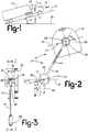
- a first embodiment of the grade and acceleration sensor 10 is shown in Figure 1 as being mounted on a vehicle, such as a tractor 12 pulling a loaded trailer 14 up a grade 16.
- the grade 16 is at an angle ⁇ with respect to the horizontal 18.
- the tractor 12 is accelerating up the grade 16 with an acceleration "a”.
- a first embodiment grade and acceleration sensor 10 is in the form of a pendulum 20 as shown in Figures 2 and 3.
- the pendulum 20 is displaced at an angle a from the longitudinal axis 22 of the tractor due to forces exerted on the pendulum 20 by gravity "g" and the acceleration "a" of the vehicle.
- the longitudinal axis 22 of the vehicle is defined as being substantially parallel to the road surface on which the vehicle is traversing.
- the grade and acceleration sensor 10 has a weighted bob 26 pivotally connected to a pivot shaft 28 by a rigid arm 30.
- the pivot shaft 28 is mounted to a mounting bracket 32 which is fixedly mountable to the vehicle by a pair of threaded fasteners (not shown) through mounting apertures 34 and 36.
- a rotary optical encoder 38 is attached to the arm 30 concentric with the axis of the pivot shaft 28 and is rotatable about the pivot shaft 28 with the angular displacement of the pendulum 20.
- a light source 40 such as a light emitting diode is disposed on one side of rotary optical encoder 38 and a photodetector 42 is disposed on the opposite side of the rotary optical encoder 38.
- the rotary optical encoder 38 may be of any type known in the art used to measure an angle of rotation.
- a strain gage 44 is attached to the arm 30 and generates an output signal having a value corresponding to the total force "F" acting on the bob 26 of the pendulum 20.
- the first force is the force mg where "m” is the weight of the bob 26 and "g” is the acceleration due to gravity.
- the force mg is the force due to gravity and is perpendicular to the horizontal 18 and is 90° - ⁇ relative to the line 24 parallel to the longitudinal axis of the vehicle.
- the second force acting on the bob 26 is the force "ma” where "m” again is the mass of the bob 26 and "a” as previously described is the acceleration of the vehicle. Movement of the grade sensor 10 perpendicular to the road will cause cyclic accelerations in the direction perpendicular to the road. However, they are cyclic and have an average value of zero over relatively short time periods.
- the two forces combine to produce a resultant force F acting on the bob 26 of the pendulum 20 which is measured by the strain gage 44.
- Equation 1 has two solutions ⁇ , and 180° - ⁇ , indicating the grade is an uphill grade or a downhill grade.
- An uphill grade can generally be distinguished from a downhill grade by the sign of ⁇ .
- memorized values of the immediately preceding grade values can provide a grade angle history usable in making a decision which of the two solutions is correct.
- the acceleration can be determined in several ways. Again, from the law of sines: where the angle ⁇ is equal to (180° - ⁇ - ⁇ ) then where the angle ⁇ is the angle between the horizontal axis of the pendulum and a vertical parallel to the force of gravity. ⁇ is equal to arc sin (F sin ⁇ /mg) .
- the acceleration a has two solutions.
- the proper solution may be derived from the prior history of the angle ⁇ and the force F.
- other clues of the vehicle acceleration or deceleration may exist to allow a choice between the two solutions.
- the acceleration may be measured directly from the change in the rotational velocity of the vehicle's drive shaft as a function of time or any other rotational member of the vehicle, such as the speedometer cable driving the vehicle's speedometer.
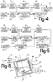
- Figure 4 is a block diagram of the circuit for generating the grade signal ⁇ from the value of the angle ⁇ of the pendulum and the force F.
- the force sensor 46 may be the strain gage 44 shown in Figures 2 and 3 and the angle sensor 50 may consist of optical angle encoder 38, light-emitting diode 40 and photodetector 42. It is recognized that other force sensors and angle sensors known in the art may be used in place of those described above.
- the pendulum Since the pendulum will be mounted on a moving vehicle, it will be subject to road noise and ordinary vehicular vibration. In order to remove these road noises and vehicular vibrations, the output signal (F) generated by the force sensor 46 will be filtered by a first road noise filter 47 and the output signal ( ⁇ ) generated by the angle sensor 50 will be filtered by a comparable road noise filter 51.
- the first and second road noise filters 47 and 51 may be low pass filters or they may be averaging circuits as is known in the art.
- a grade angle generator 48 will compute the grade angle ⁇ using Equation (1) and the grade angle logic 49 will determine its correct solution from the value of the acceleration determined by the solution of Equation (1) and the prior history of the values of F and ⁇ .
- the grade angle ⁇ may then be used by a utilization device 60 such as an anti-lock brake system or an automatic or semi-automatic transmission.
- An acceleration value generator 52 will generate an acceleration value "a" using Equation (2) and the accel/decel logic 58 will determine the correct solution of Equation (2) from the prior history of the values of the grade angle ⁇ and the value of the acceleration a.
- the value of the acceleration a is also received by the utilization device 60.
- Figure 5 shows an alternate grade angle sensor system which includes an acceleration direction sensor 54 which generates a first acceleration signal in response to the change in the rotational velocity of vehicle engine or drivetrain.
- the force sensor 46, the angle sensor 50, the first and second road noise filters 47 and 51, the grade angle signal generator 48, and the acceleration value generator 52 are essentially the same as shown in Figure 4.
- the grade angle logic 56 and the accel/decel logic 58 select the correct values of the grade angle ⁇ and the value of the acceleration "a" in response to the signal received from the acceleration sensor 54
- An alternate embodiment of the grade sensor 62 is shown in Figure 6.
- the grade sensor 62 has a box-like housing structure 64 mountable to the frame of the vehicle 12.
- the grade sensor 62 has a weight 66 having a mass m mounted wihin the box-like structure 64.
- the weight 66 may be square as shown, but alternately may be circular, octagonal, or any other shape desired.
- the weight is biased by two orthogonally disposed leaf springs 68 and 70 against two orthogonally disposed piezoelectric crystals 72 and 74.
- leaf springs and piezoelectric crystals are oriented such that leaf spring 70 and piezoelectric crystal 74 define the x axis of the grade sensor 62 and leaf spring 68 and piezoelectric crystal 72 define the y axis.
- the grade sensor is mounted on the vehicle with the x axis parallel to the vehicle's longitudinal axis 22 and the "y" axis normal to the vehicle's longitudinal axis.
- Piezoelectric crystal 72 is connected to an oscillator circuit 76 which generates an output signal having a frequency f, which is variable as the function of the force applied to the piezoelectric crystal 72 by the weight 66 and leaf spring 68.
- piezoelectric crystal 74 is connected to an oscillator circuit which generates an output signal having a frequency f2 which is variable as a function of the force applied to piezoelectric crystal 74 by the weight 66 and leaf spring 70.
- the frequencies f1 and f2 correspond to the individual orthogonal forces acting on the piezoelectric crystals 72 and 74.
- the frequency f1 of the output signal of the oscillator circuit 76 will vary as the sensor is rotated relative to the force of gravity F g due to the vehicle ascending or descending a grade ⁇ .
- the piezoelectric crystal 72 is substantially insensitive to acceleration of the vehicle along the vehicle's longitudinal axis 22. Therefore, the frequency of oscillator 76 will not change as a function of vehicle acceleration or deceleration.
- piezoelectric crystal 74 is sensitive to both acceleration and deceleration of the vehicle along its longitudinal axis and an angular rotation due to the vehicle ascending or descending a road grade disposed at an angle ⁇ relative to the horizontal.
- the angle ⁇ may be derived from the equation: ⁇ - arc cos ( F 1/ F 0) (3) where F0 is the force on piezoelectric crystal 72 exerted by the weight 66 when the x axis of the sensor is horizontal and F1 is the force on the piezoelectric crystal 72 exerted by the weight 66 when the x axis of the sensor is at an angle ⁇ to the horizontal.
- the frequency f2 is proportional to the total force F'' acting on piezoelectric crystal 74
- f2 is proportional to the force F2 exerted by weight 66 due to acceleration
- the force F3 is the force exerted by the weight 66 due to gravity when the sensor is rotated relative to the horizontal
- the force F S2 is the force exerted by leaf spring 70.
- the calculation for the values of the grade angle ⁇ and the acceleration a will have two values and, as discussed relative to the grade sensor illustrated in Figures 1-3.
- the appropriate value may be selected from a past history of the value the grade angle ⁇ and the acceleration a.
- FIG 7 is a block diagram of the electronic circuit for generating the grade angle ⁇ and the acceleration "a".
- a y-axis sensor 80 generates a signal having the value F1 in response to the force F'.
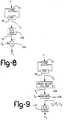
- the y-axis sensor 80 as shown in Figure 8, comprises the piezoelectric crystal 72, the oscillator circuit 76, a frequency to analog (F/A) converter 102 which converts the frequency f1 to an analog signal having a value proportional to the total force F' acting on piezoelectric crystal 72.
- Sum amplifier 104 subtracts from the analog signal a reference signal F S1 corresponding to the portion of the total force F' produced by the leaf spring 68.
- the output of the sum amplifier 104 is the signal F1 corresponding to the force exerted by the weight 66 only.
- the output of the y-axis sensor 80 is filtered by a road noise filter 82 which outputs a filter signal F ⁇ 1.
- a grade angle generator 84 generates a pair of grade angle signals, ⁇ and 180 - ⁇ , which is received by a grade angle logic circuit 86 and an F3 generator 92.
- the grade angle logic circuit 86 selects the proper grade angle based on the prior history of the grade angle ⁇ and the acceleration "a".
- An x-axis sensor 88 generates an analog signal F T corresponding to the sum of forces F2 and F3 acting on piezoelectric crystal 74 by weight 66 due to acceleration and the force of gravity.
- the structure of the x-axis sensor 88 is substantially the same as structure of the y-axis sensor 80 shown in Figure 8 and therefore need not be described in detail.
- the signal F T is filtered by a road noise filter 90 to remove road noise from the signal F T .
- the filtered signal F ⁇ T is received at the + input of a sum amplifier 94 while the signal F3 from the F3 generator 92 is received at a negative input.
- An acceleration value generator 96 converts the force F2 to an acceleration value which has two possible values, +a for acceleration and -a for deceleration.
- An accel/decel logic circuit 98 selects either the acceleration value "+a” or the deceleration value "-a” based on the prior history of the grade angle ⁇ and the acceleration value.
- the circuit shown in Figure 7 may include an acceleration/deceleration sensor 100 shown in phantom, responsive to the time derivative of a moving member of the vehicle's drivetrain to generate a signal having a first value signifying an acceleration condition and a second value signifying a deceleration condition.
- This signal is received by the grade angle logic circuit 86 and the accel/decel logic 98 simplifying the logic for selecting the proper value.
- Figure 9 shows an alternate circuit arrangement for generating the signals F1 and F T . Since the circuits for generating F1 and F T are substantially identical, only the circuit for generating F1 will be described in detail.
- the oscillator 76 and piezoelectric crystal 72 generate a frequency f1 in response to the force F1 exerted on crystal 72.
- a road noise filter 106 frequency filters the frequency f1 to generate a filtered frequency signal f ⁇ 1.
- the filtered frequency signal f ⁇ 1 is mixed with a reference frequency f s in a mixer circuit 108.
- the frequency f s corresponds to the force exerted by the leaf spring 68 on piezoelectric crystal 72.
- a frequency-to-analog converter 110 converts the difference frequency ( f ⁇ 1-f s ) which corresponds to the force f w exerted only by the force of gravity acting on the weight 66 to an analog signal F1 corresponding to the value of the force exerted by gravity on the weight 66.
Landscapes
- Physics & Mathematics (AREA)
- General Physics & Mathematics (AREA)
- Engineering & Computer Science (AREA)
- Radar, Positioning & Navigation (AREA)
- Remote Sensing (AREA)
- Vehicle Body Suspensions (AREA)
- Combined Controls Of Internal Combustion Engines (AREA)
- Electric Propulsion And Braking For Vehicles (AREA)
- Hydraulic Control Valves For Brake Systems (AREA)
- Gyroscopes (AREA)
- Navigation (AREA)
Applications Claiming Priority (2)
| Application Number | Priority Date | Filing Date | Title |
|---|---|---|---|
| US954665 | 1992-09-30 | ||
| US07/954,665 US5351540A (en) | 1992-09-30 | 1992-09-30 | Grade angle and acceleration sensor |
Publications (1)
| Publication Number | Publication Date |
|---|---|
| EP0590312A1 true EP0590312A1 (fr) | 1994-04-06 |
Family
ID=25495764
Family Applications (1)
| Application Number | Title | Priority Date | Filing Date |
|---|---|---|---|
| EP93113651A Withdrawn EP0590312A1 (fr) | 1992-09-30 | 1993-08-26 | Capteur pour la déclivité et l'accélération |
Country Status (11)
| Country | Link |
|---|---|
| US (1) | US5351540A (fr) |
| EP (1) | EP0590312A1 (fr) |
| JP (1) | JPH06201380A (fr) |
| KR (1) | KR940007539A (fr) |
| CN (1) | CN1085656A (fr) |
| AR (1) | AR248193A1 (fr) |
| AU (1) | AU660109B2 (fr) |
| BR (1) | BR9303561A (fr) |
| CA (1) | CA2105240A1 (fr) |
| MX (1) | MX9306117A (fr) |
| ZA (1) | ZA937158B (fr) |
Cited By (4)
| Publication number | Priority date | Publication date | Assignee | Title |
|---|---|---|---|---|
| WO1998047109A1 (fr) * | 1997-04-17 | 1998-10-22 | Stage Iii Technologies, L.C. | Dispositif d'enregistrement, de localisation, et de transmission de donnees relatives a l'accident d'un vehicule |
| EP0707213A3 (fr) * | 1994-10-11 | 1999-12-08 | Fujikura Ltd. | Capteur d'accélération asservi et procédé de calcul de l'accélération d'un véhicule le long d'une pente |
| EP1626248A1 (fr) * | 2004-08-09 | 2006-02-15 | Bomag Gmbh | Dispositif et procédé pour déterminer un angle d'inclinaison indépendant de l'accélération |
| WO2013105869A1 (fr) | 2012-01-13 | 2013-07-18 | Pulse Function F6 Limited | Système télématique avec des capteurs inertiels 3d |
Families Citing this family (33)
| Publication number | Priority date | Publication date | Assignee | Title |
|---|---|---|---|---|
| KR100207106B1 (ko) * | 1994-04-06 | 1999-07-15 | 정몽규 | 자동차 주행도로의 기울기 측정장치 및 그 방법 |
| DE19538616C2 (de) * | 1995-10-17 | 2003-11-27 | Continental Teves Ag & Co Ohg | Vorrichtung zur Erfassung einer Fahrzeugneigung und/oder einer Fahrzeugbeschleunigung |
| US5723782A (en) * | 1996-11-29 | 1998-03-03 | Bolles, Jr.; Robert C. | Method of land vehicle suspension evaluation and design through roll angle analysis |
| KR100462745B1 (ko) * | 1996-12-31 | 2005-04-06 | 현대자동차주식회사 | 차량 전복사고시 안전장치 |
| DE19814357A1 (de) * | 1998-03-31 | 1999-10-07 | Maha Gmbh & Co Kg | Meßgerät zur Fahrzeugdiagnose |
| KR100308572B1 (ko) * | 1998-11-09 | 2001-11-30 | 김덕중 | 자이로와 가속도계를 이용한 경사각 및 차량속도 검출장치 |
| GB2353573B (en) * | 1999-08-24 | 2002-01-02 | Bosch Gmbh Robert | Method and device for adjusting the braking action at the wheels of a motor vehicle |
| US6873931B1 (en) | 2000-10-10 | 2005-03-29 | Csi Technology, Inc. | Accelerometer based angular position sensor |
| DE60120628T2 (de) * | 2001-01-29 | 2006-12-28 | Ford Global Technologies, LLC, Dearborn | Beladungsschätzer |
| US7058499B2 (en) * | 2003-05-20 | 2006-06-06 | Kds Controls | Brake control system and method |
| SE527413C2 (sv) * | 2004-07-02 | 2006-02-28 | Volvo Lastvagnar Ab | Motordrivet fordon med transmission |
| DE102006020471B4 (de) * | 2006-04-28 | 2008-01-03 | Trajet Gmbh | Messeinrichtung für Fahrzeugdaten, insbesondere für die Geschwindigkeit eines auf Rädern laufenden Fahrzeuges |
| KR20090001721A (ko) * | 2007-05-14 | 2009-01-09 | 팅크웨어(주) | 맵 매칭 보정 방법 및 상기 방법을 수행하는 내비게이션시스템 |
| US7757406B2 (en) * | 2007-05-29 | 2010-07-20 | Sepehr Khashaei | Vehicle travel grade indicator (VTGI) |
| CZ303131B6 (cs) * | 2008-02-05 | 2012-04-25 | ŠKODA TRANSPORTATION a.s. | Zpusob stanovení redukovaného sklonu trate projíždené vozidlem |
| US8401753B2 (en) * | 2009-11-23 | 2013-03-19 | Caterpillar Inc. | Automatic downhill speed control system |
| CN102141622A (zh) * | 2010-01-28 | 2011-08-03 | 杨志雄 | 探索环境绘制三维空间地图的自走式测量设备 |
| WO2012124009A1 (fr) * | 2011-03-17 | 2012-09-20 | 三菱電機株式会社 | Dispositif de détection de l'inclinaison d'un véhicule |
| WO2013011522A1 (fr) * | 2011-07-21 | 2013-01-24 | Zen Technologies Ltd. | Appareil et procédé pour mesurer un écart angulaire vertical |
| CN103358985A (zh) * | 2012-04-09 | 2013-10-23 | 周亦武 | 汽车加速度显示装置 |
| CN103673984A (zh) * | 2012-09-05 | 2014-03-26 | 昆山研达电脑科技有限公司 | 坡度感测装置 |
| DE102014214965B4 (de) * | 2014-07-30 | 2017-02-02 | Robert Bosch Gmbh | Vorrichtung und Verfahren zur Erzeugung eines Steigungswertes |
| CN104215224A (zh) * | 2014-09-10 | 2014-12-17 | 西南大学 | 一种用线性霍尔传感器检测倾角和加速度的装置及方法 |
| CN105116167A (zh) * | 2015-09-10 | 2015-12-02 | 深圳威易森科技有限公司 | 一种机动车在坡度平面行驶时的加速度确定方法 |
| CN107132377A (zh) * | 2017-06-13 | 2017-09-05 | 南京越博动力系统股份有限公司 | 一种车辆加速度及所处坡度的测量装置与计算方法 |
| TWI673477B (zh) * | 2018-06-26 | 2019-10-01 | 晶翔機電股份有限公司 | 表面斜度鑑別裝置及其鑑別方法 |
| KR102193035B1 (ko) * | 2020-04-09 | 2020-12-18 | 김용수 | 이동하중을 이용한 쏠림 감지 및 제어 장치 |
| CN114684159B (zh) * | 2022-03-21 | 2024-08-16 | 潍柴动力股份有限公司 | 一种车辆质量估算方法、装置、电子设备和存储介质 |
| CN114852086A (zh) * | 2022-04-27 | 2022-08-05 | 中国第一汽车股份有限公司 | 一种坡度值确定设备、方法、装置、电子设备和存储介质 |
| KR102490250B1 (ko) * | 2022-07-05 | 2023-01-20 | 한동건설엔지니어링(주) | 하이브리드 기울기 측정장치 |
| CN115158038B (zh) * | 2022-07-29 | 2025-04-22 | 南京经纬达汽车科技有限公司 | 一种用于坡道起步和陡坡缓降的加速度传感器 |
| KR102504933B1 (ko) * | 2022-09-15 | 2023-03-02 | 국방과학연구소 | 고감도 압축형 압전 가속도계 |
| CN118770232A (zh) * | 2024-08-16 | 2024-10-15 | 中国重汽集团济南动力有限公司 | 一种车辆所处坡度的计算方法、系统、终端及存储介质 |
Citations (8)
| Publication number | Priority date | Publication date | Assignee | Title |
|---|---|---|---|---|
| US3537307A (en) * | 1968-10-10 | 1970-11-03 | Donald J Pliha | Self-compensated pendulous inertial reference apparatus for vehicles |
| FR2070784A1 (fr) * | 1969-12-09 | 1971-09-17 | Gen Motors Corp | |
| US4356638A (en) * | 1980-10-22 | 1982-11-02 | Leveling Devices, Inc. | Lift truck digital inclinometer |
| JPS60166817A (ja) * | 1984-02-09 | 1985-08-30 | Aisin Warner Ltd | 傾斜検出器 |
| WO1986001607A1 (fr) * | 1984-09-05 | 1986-03-13 | Poetsch Edmund R | Procede et appareil pour determiner au moins une valeur caracteristique du mouvement d'un corps |
| JPS61155911A (ja) * | 1984-12-28 | 1986-07-15 | Daihatsu Motor Co Ltd | 傾斜・加速度検出装置 |
| JPH01267463A (ja) * | 1988-04-19 | 1989-10-25 | Fujitsu Ten Ltd | 車体加速度の検出装置 |
| US5134883A (en) * | 1990-09-27 | 1992-08-04 | Shannon E Paul | Pendulum-type accelerometer |
Family Cites Families (4)
| Publication number | Priority date | Publication date | Assignee | Title |
|---|---|---|---|---|
| GB1206713A (en) * | 1968-01-19 | 1970-09-30 | Westinghouse Brake & Signal | Improvements in or relating to devices responsive to change in their velocities |
| US3752251A (en) * | 1969-12-09 | 1973-08-14 | Gen Motors Corp | Road grade sensor |
| DE3334726A1 (de) * | 1983-09-26 | 1985-04-11 | Wabco Westinghouse Fahrzeug | Steuereinrichtung fuer ein strassenfahrzeug |
| DE4010073A1 (de) * | 1990-03-29 | 1991-10-02 | Wabco Westinghouse Fahrzeug | Einrichtung zur bergfahrt-erkennung |
-
1992
- 1992-09-30 US US07/954,665 patent/US5351540A/en not_active Expired - Fee Related
-
1993
- 1993-08-26 EP EP93113651A patent/EP0590312A1/fr not_active Withdrawn
- 1993-08-31 CA CA002105240A patent/CA2105240A1/fr not_active Abandoned
- 1993-09-14 AU AU47347/93A patent/AU660109B2/en not_active Ceased
- 1993-09-16 KR KR1019930018636A patent/KR940007539A/ko not_active Ceased
- 1993-09-27 JP JP5262887A patent/JPH06201380A/ja active Pending
- 1993-09-27 ZA ZA937158A patent/ZA937158B/xx unknown
- 1993-09-28 AR AR93326149A patent/AR248193A1/es active
- 1993-09-29 BR BR9303561A patent/BR9303561A/pt not_active IP Right Cessation
- 1993-09-30 MX MX9306117A patent/MX9306117A/es unknown
- 1993-09-30 CN CN93118450A patent/CN1085656A/zh active Pending
Patent Citations (8)
| Publication number | Priority date | Publication date | Assignee | Title |
|---|---|---|---|---|
| US3537307A (en) * | 1968-10-10 | 1970-11-03 | Donald J Pliha | Self-compensated pendulous inertial reference apparatus for vehicles |
| FR2070784A1 (fr) * | 1969-12-09 | 1971-09-17 | Gen Motors Corp | |
| US4356638A (en) * | 1980-10-22 | 1982-11-02 | Leveling Devices, Inc. | Lift truck digital inclinometer |
| JPS60166817A (ja) * | 1984-02-09 | 1985-08-30 | Aisin Warner Ltd | 傾斜検出器 |
| WO1986001607A1 (fr) * | 1984-09-05 | 1986-03-13 | Poetsch Edmund R | Procede et appareil pour determiner au moins une valeur caracteristique du mouvement d'un corps |
| JPS61155911A (ja) * | 1984-12-28 | 1986-07-15 | Daihatsu Motor Co Ltd | 傾斜・加速度検出装置 |
| JPH01267463A (ja) * | 1988-04-19 | 1989-10-25 | Fujitsu Ten Ltd | 車体加速度の検出装置 |
| US5134883A (en) * | 1990-09-27 | 1992-08-04 | Shannon E Paul | Pendulum-type accelerometer |
Non-Patent Citations (4)
| Title |
|---|
| K.SHIMIZU ET AL: "onboard measurement of road inclination", MEASUREMENT, vol. 6, no. 2, April 1988 (1988-04-01), LONDON GB, pages 87 - 93 * |
| PATENT ABSTRACTS OF JAPAN vol. 010, no. 009 (P - 420) 14 January 1986 (1986-01-14) * |
| PATENT ABSTRACTS OF JAPAN vol. 010, no. 358 (P - 522) 2 December 1986 (1986-12-02) * |
| PATENT ABSTRACTS OF JAPAN vol. 014, no. 027 (P - 992) 19 January 1990 (1990-01-19) * |
Cited By (4)
| Publication number | Priority date | Publication date | Assignee | Title |
|---|---|---|---|---|
| EP0707213A3 (fr) * | 1994-10-11 | 1999-12-08 | Fujikura Ltd. | Capteur d'accélération asservi et procédé de calcul de l'accélération d'un véhicule le long d'une pente |
| WO1998047109A1 (fr) * | 1997-04-17 | 1998-10-22 | Stage Iii Technologies, L.C. | Dispositif d'enregistrement, de localisation, et de transmission de donnees relatives a l'accident d'un vehicule |
| EP1626248A1 (fr) * | 2004-08-09 | 2006-02-15 | Bomag Gmbh | Dispositif et procédé pour déterminer un angle d'inclinaison indépendant de l'accélération |
| WO2013105869A1 (fr) | 2012-01-13 | 2013-07-18 | Pulse Function F6 Limited | Système télématique avec des capteurs inertiels 3d |
Also Published As
| Publication number | Publication date |
|---|---|
| CA2105240A1 (fr) | 1994-03-31 |
| ZA937158B (en) | 1994-05-23 |
| AR248193A1 (es) | 1995-06-30 |
| US5351540A (en) | 1994-10-04 |
| KR940007539A (ko) | 1994-04-27 |
| CN1085656A (zh) | 1994-04-20 |
| MX9306117A (es) | 1995-01-31 |
| AU660109B2 (en) | 1995-06-08 |
| AU4734793A (en) | 1994-04-14 |
| JPH06201380A (ja) | 1994-07-19 |
| BR9303561A (pt) | 1994-05-24 |
Similar Documents
| Publication | Publication Date | Title |
|---|---|---|
| US5351540A (en) | Grade angle and acceleration sensor | |
| EP1271098B1 (fr) | Dispositif et procédé pour évaluer des pentes de chaussée, et logiciel pour évaluer des pentes | |
| EP1013525B1 (fr) | Méthode et appareil pour déterminer la stabilité dynamique d'un véhicule automobile | |
| US6339749B1 (en) | Device for determining the weight of a motor vehicle | |
| US5925087A (en) | Method and apparatus for eliminating noise in a slope estimation arrangement for a motor vehicle | |
| Kobayashi et al. | Estimation of absolute vehicle speed using fuzzy logic rule-based Kalman filter | |
| US5825284A (en) | System and method for the detection of vehicle rollover conditions | |
| US5742919A (en) | Method and apparatus for dynamically determining a lateral velocity of a motor vehicle | |
| US6816804B1 (en) | System and method for estimating velocity using reliability indexed sensor fusion | |
| KR100385377B1 (ko) | 회전축상의 토오크를 계산하기 위한 장치 및 방법 | |
| JPH02201240A (ja) | 自動車の質量検出装置 | |
| US20070179735A1 (en) | Method and arrangement for monitoring a measuring device located in a wheeled vehicle | |
| FR2719260B1 (fr) | Agencement de commande d'un systeme d'amortisseurs de train de roulement d'un vehicule | |
| JPH0153434B2 (fr) | ||
| EP0126052A2 (fr) | Méthode pour indiquer le dérapage d'un élément d'entraînement rotatif | |
| US20010054310A1 (en) | Process for improved determination of the ratio among the radii of the wheels of a vehicle | |
| HU200432B (en) | Measuring method and apparatus for qualifying the condition of railway tracks | |
| US5373446A (en) | Vehicle ground-speed detecting apparatus | |
| JPH02105023A (ja) | 車両計量方法および装置 | |
| US6427130B1 (en) | Method and device for regulating a quantity of motion representing the movement of a vehicle | |
| JPH08509442A (ja) | ホイールセンサ信号を調整及び評価する回路構成 | |
| JP2010076700A (ja) | タイヤの輪荷重推定方法及び装置、並びにタイヤの輪荷重推定プログラム | |
| JP2843905B2 (ja) | 車両用慣性航法装置 | |
| JPH05272974A (ja) | 車両用路面勾配検出装置 | |
| JPH0477244B2 (fr) |
Legal Events
| Date | Code | Title | Description |
|---|---|---|---|
| PUAI | Public reference made under article 153(3) epc to a published international application that has entered the european phase |
Free format text: ORIGINAL CODE: 0009012 |
|
| AK | Designated contracting states |
Kind code of ref document: A1 Designated state(s): DE ES FR GB IT SE |
|
| 17P | Request for examination filed |
Effective date: 19940922 |
|
| 17Q | First examination report despatched |
Effective date: 19960305 |
|
| GRAG | Despatch of communication of intention to grant |
Free format text: ORIGINAL CODE: EPIDOS AGRA |
|
| RAP1 | Party data changed (applicant data changed or rights of an application transferred) |
Owner name: DANA CORPORATION |
|
| GRAG | Despatch of communication of intention to grant |
Free format text: ORIGINAL CODE: EPIDOS AGRA |
|
| GRAH | Despatch of communication of intention to grant a patent |
Free format text: ORIGINAL CODE: EPIDOS IGRA |
|
| GRAH | Despatch of communication of intention to grant a patent |
Free format text: ORIGINAL CODE: EPIDOS IGRA |
|
| 18D | Application deemed to be withdrawn |
Effective date: 19990119 |