EP0590330A1 - Cylindre de serrure - Google Patents
Cylindre de serrure Download PDFInfo
- Publication number
- EP0590330A1 EP0590330A1 EP93113967A EP93113967A EP0590330A1 EP 0590330 A1 EP0590330 A1 EP 0590330A1 EP 93113967 A EP93113967 A EP 93113967A EP 93113967 A EP93113967 A EP 93113967A EP 0590330 A1 EP0590330 A1 EP 0590330A1
- Authority
- EP
- European Patent Office
- Prior art keywords
- cylinder
- coupling element
- core
- lock
- housing
- Prior art date
- Legal status (The legal status is an assumption and is not a legal conclusion. Google has not performed a legal analysis and makes no representation as to the accuracy of the status listed.)
- Granted
Links
Images





Classifications
-
- B—PERFORMING OPERATIONS; TRANSPORTING
- B60—VEHICLES IN GENERAL
- B60R—VEHICLES, VEHICLE FITTINGS, OR VEHICLE PARTS, NOT OTHERWISE PROVIDED FOR
- B60R25/00—Fittings or systems for preventing or indicating unauthorised use or theft of vehicles
- B60R25/01—Fittings or systems for preventing or indicating unauthorised use or theft of vehicles operating on vehicle systems or fittings, e.g. on doors, seats or windscreens
- B60R25/02—Fittings or systems for preventing or indicating unauthorised use or theft of vehicles operating on vehicle systems or fittings, e.g. on doors, seats or windscreens operating on the steering mechanism
- B60R25/021—Fittings or systems for preventing or indicating unauthorised use or theft of vehicles operating on vehicle systems or fittings, e.g. on doors, seats or windscreens operating on the steering mechanism restraining movement of the steering column or steering wheel hub, e.g. restraining means controlled by ignition switch
- B60R25/0211—Fittings or systems for preventing or indicating unauthorised use or theft of vehicles operating on vehicle systems or fittings, e.g. on doors, seats or windscreens operating on the steering mechanism restraining movement of the steering column or steering wheel hub, e.g. restraining means controlled by ignition switch comprising a locking member radially and linearly moved towards the steering column
- B60R25/02115—Fittings or systems for preventing or indicating unauthorised use or theft of vehicles operating on vehicle systems or fittings, e.g. on doors, seats or windscreens operating on the steering mechanism restraining movement of the steering column or steering wheel hub, e.g. restraining means controlled by ignition switch comprising a locking member radially and linearly moved towards the steering column key actuated
-
- E—FIXED CONSTRUCTIONS
- E05—LOCKS; KEYS; WINDOW OR DOOR FITTINGS; SAFES
- E05B—LOCKS; ACCESSORIES THEREFOR; HANDCUFFS
- E05B17/00—Accessories in connection with locks
- E05B17/04—Devices for coupling the turning cylinder of a single or a double cylinder lock with the bolt operating member
Definitions
- the invention relates to a lock cylinder, in particular a motor vehicle lock, with a cylinder core with a key channel and tumblers, which, when the key is wrong, lie in the cylinder housing, which surrounds the cylinder core, and rotate the cylinder housing, overcoming a catch, and which, with the correct key, freely oppose the cylinder core let the cylinder housing rotate, whereby due to the free rotation of the cylinder core relative to the cylinder housing, the cylinder core takes along a coupling element that runs onto an inclined surface of the cylinder housing and thus executes a movement that allows the coupling element to be coupled to a transmission part that performs a closing function directly and indirectly .
- Such a locking cylinder is known from European patent 0 341 132.
- the coupling element is mounted coaxially and thus centrally, so that the lock in the axial direction receives a relatively large height.
- the object of the invention is to improve a lock cylinder of the type mentioned in such a way that with simple construction and handling as well as great reliability there are small external dimensions and weight.
- the coupling element is mounted on the outside of the cylinder core and a spring element bears against it, which acts on the coupling element against its coupling movement.
- the coupling element can be accommodated in a space-saving manner due to its outer-centered storage, the functionality not being reduced.
- the coupling element is an axially parallel pin that is axially movable.
- the coupling element can be a swivel part that is movable about an axis tangential to the cylinder core or parallel to the tangent axis. It is also advantageous if the swivel part is approximately in the form of a segment of a circle and moves with a side edge toward the closing axis for coupling.
- the coupling element be mounted in a radially movable manner in the cylinder.
- the coupling element can run with an outer projection on a short lateral circumferential path.
- a locking plate is mounted in the control cam so that it can be secured against theft and secured to the cylinder core.
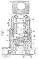
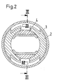
- the steering lock has a stepped cylindrical lock housing 1, in which is coaxially mounted a cylinder housing 2, which consists of an inner cylinder housing 2a and an outer cylinder housing 2b, which are inserted coaxially into one another.
- the inner cylinder housing 2a has radial recesses 2c, into which the plate-like tumblers 3 partially protrude when an incorrect key is inserted.
- the tumblers 3 are arranged in radially displaceable recesses in a cylinder core 4.
- the cylinder core 4 is rotatably mounted coaxially in the cylinder housing 2 and has a longitudinal channel for the key 6.
- the known functional principle of this locking cylinder is that if the wrong key is inserted, the tumblers 3 connect the cylinder housing to the cylinder core in a rotationally fixed manner, so that when the key 6 is turned, both the cylinder core 4 and the cylinder housing 2 are rotated.
- the cylinder housing overcomes a detent and the cylinder core and cylinder housing can be freely rotated using the wrong key or an inserted burglary tool.
- the cylinder core 4 is rotated by the key, however not the cylinder housing as it is held by the detent.
- the relative movement of the cylinder core relative to the cylinder housing produces a movement of a coupling element which connects the cylinder core to a further part (transmission part 7) which is arranged on the end of the cylinder core which is remote from the key insertion side. This results in a coupling of the cylinder core 4 with a transmission part 7.
- the cylinder core 4 is mounted coaxially in an inner cylinder housing 2a, which is coaxially surrounded by an outer cylinder housing 2b, so that the cylinder housing is made in two parts. This division into two has no meaning for the function but was made to facilitate manufacture and assembly.
- an axially parallel pin 8a is mounted as a coupling element which lies in an axially parallel bore 10 of the cylinder core 4 and is surrounded there by a spring 9 which acts on the pin towards the key insertion side.
- the inner end of the cylinder core 4 forms an annular collar 4a, which projects laterally and from which the pin 8a projects with a head 11 which lies in a recess 12 in the inner cylinder housing 2a.
- the recess 12 forms an inclined surface, so that when the cylinder core 4 rotates relative to the inner cylinder housing 2a, the head 11 runs up on the inclined surface and the end of the pin 8a opposite the head 11 comes out of the annular collar 4a as far as possible.
- the cylinder core 4 is coupled to the transmission part 7, so that not only the cylinder core 4 but also the transmission part 7 and the parts behind the transmission part 7, in particular the control cam 14, which rotates a locking bolt slide 16 with its control camshaft 15 when the key is turned transversely displaces, which either forms the locking bolt 17 itself or is connected to the locking bolt 17, which moves into a recess 18 in the longitudinal spindle 19 in order to block the steering, see FIG. 7.
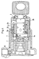
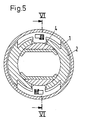
- a pivot part 8b can also be rotatably mounted as a coupling element off-center on the cylinder core 4 or on the annular collar 4a of the cylinder core.
- the axis of rotation of this swivel part 8b is approximately tangential to the outside of the cylinder core 4.
- the swivel part 8b has the shape of a circular segment and lies with an approximately radial side edge on an inner end face of the cylinder housing 2. If the cylinder core 4 is rotated relative to the cylinder housing 2 with the correct key, the edge 20 runs along a curve along the end face of the cylinder housing, the pivoting part 8b being rotated so that the opposite, approximately radial edge 21 of the pivoting part 8b into a recess in the transmission part 7 penetrates so that the cylinder core rotates the transmission part 7 in order to actuate the locking bolt 17 via intermediate parts.
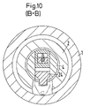
- the coupling element 8c consists of a slide 8c, in particular radially movable, on which a nose 22 protrudes laterally axially parallel, which runs along a curve 23 along the cylinder housing 2. If the cylinder core 4 is rotated with respect to the cylinder housing 2, the slide 8c which is mounted in the cylinder core 4 so as to be transversely displaceable is also rotated and the nose 22 runs along the curve 23 and is moved radially outward. In the outermost position, the outside of the nose 22 or an outer region of the slide 8c penetrates into a groove 23 of the control cam 14, so that the slide 8c uncouples the cylinder core 4 from the control cam 14. The further rotary movement of the cylinder core 4 thus leads to a corresponding rotation of the control cam 14 and in turn to an actuation of the locking bolt 17 as well as the electrical rotary switch into which the shaft 15 extends.
- FIGS. 7 to 12 still has a locking plate 24 which is mounted transversely in the control cam 14 and ensures that the control cam 14 is so securely attached to the cylinder core 4 that it does not break in the event of a violent break of the lock Rotary switch side can be removed.
- a lifting rod 25 which is mounted laterally on the cylinder housing within the lock housing, ensures that the control cam 14 is held in the retracted position in this locked position by the inner end of the lifting rod 25 against a stop of the control cam 14 is present.
- a in the cylinder core 4 radially near the key insertion side slider 26 rests with one end on the key and the other end on the lifting rod 25 and ensures that the lifting rod is only released when the key is removed.
- a lever 26 can also be mounted on the side of the cylinder housing, as shown in the exemplary embodiments in FIGS. 1 to 6.
- the lock has the following functions: Due to the slipping clutch, the locking cylinder 4 protruding from the housing remains radially free in the event of incorrect actuation or when actuated with an incorrect locking element 6, without causing a closing / switching operation. Only the correct key 6 causes the core 4 and the control cam 14 to be coupled by an eccentrically guided driver (coupling element 8a, 8b or 8c) and to enable the locking function.
- the slip clutch increases the security of the ignition steering lock, making it difficult to deliberately damage it with the wrong key or a break-open tool.
- the core 4 and the cylinder housing 2 remain a connected, form-fitting element through the tumbler / s 3, which element is radially freely movable in the steering lock housing 1.
- the form-fitting element is positioned axially in the cylinder housing 2 by a bolt 30.
- the bolt 30 slides in the circumferential recess of the steering lock housing 1.
- the lifting rod 25 maintains the original function, closing only after the key has been removed.
- the cylindrical core end slides freely in the stationary control cam 14.
- the lifting rod 25 is guided axially in the cylinder housing 2.
- the LATCH FUNCTION causes the lifting rod to be lifted.
- the locking cylinder when it is outside the locking position of the lifting rod and is operated by the correct key, is also moved into the locking position (zero position) of the lifting rod 25. Only then can the lifting rod snap into the steering lock housing 7. The cylinder pin 32 of the lifting rod thereby unlocks the core 4 and the cylinder housing 2. The normal closing can be initiated.
- the groove 33 in the core prevents the cylinder pin 32 of the lifting rod 25 from sliding. a deflection of the lifting rod and thus locks the cylinder housing 2 with the steering lock housing 1.
- the correct key 6 enables the core 4 to be rotated relative to the cylinder housing.
- a driver 8c is guided perpendicular to the central axis.
- the driver 8c is moved eccentrically in the groove which is in the flat surface at the end of the cylinder housing 2.
- the eccentrically moved driver 8c corresponds to a feather key that uses the control cam 14.
- the driver remains eccentrically guided in the groove at the same distance from the central axis.
- control cam In order to prevent tampering with the control cam 14 from the ignition starter switch, the control cam is axially secured by the securing plate 24. This prevents a thief from pulling and turning the control cam with a pair of pliers to unlock the steering lock. With key operation, the locking plate 24 is pulled in the towing of the driver and the control cam is released axially.
Landscapes
- Engineering & Computer Science (AREA)
- Mechanical Engineering (AREA)
- Lock And Its Accessories (AREA)
Applications Claiming Priority (2)
| Application Number | Priority Date | Filing Date | Title |
|---|---|---|---|
| DE4233029 | 1992-10-01 | ||
| DE4233029A DE4233029C2 (de) | 1992-10-01 | 1992-10-01 | Schließzylinder |
Publications (2)
| Publication Number | Publication Date |
|---|---|
| EP0590330A1 true EP0590330A1 (fr) | 1994-04-06 |
| EP0590330B1 EP0590330B1 (fr) | 1999-04-07 |
Family
ID=6469395
Family Applications (1)
| Application Number | Title | Priority Date | Filing Date |
|---|---|---|---|
| EP93113967A Expired - Lifetime EP0590330B1 (fr) | 1992-10-01 | 1993-09-01 | Cylindre de serrure |
Country Status (4)
| Country | Link |
|---|---|
| EP (1) | EP0590330B1 (fr) |
| BR (1) | BR9303976A (fr) |
| DE (2) | DE4233029C2 (fr) |
| ES (1) | ES2131085T3 (fr) |
Cited By (1)
| Publication number | Priority date | Publication date | Assignee | Title |
|---|---|---|---|---|
| WO2013014173A1 (fr) * | 2011-07-25 | 2013-01-31 | Valeo Securite Habitacle | Dispositif antivol pour colonne de direction et colonne de direction associée |
Families Citing this family (1)
| Publication number | Priority date | Publication date | Assignee | Title |
|---|---|---|---|---|
| DE10317449A1 (de) * | 2003-04-16 | 2004-11-04 | Aug. Winkhaus Gmbh & Co. Kg | Kupplungseinrichtung an Doppelschließzylinder und Doppelschließzylinder |
Citations (7)
| Publication number | Priority date | Publication date | Assignee | Title |
|---|---|---|---|---|
| US1582425A (en) * | 1924-08-25 | 1926-04-27 | Sewell Cushion Wheel Company | Wheel lock |
| US2049742A (en) * | 1933-04-22 | 1936-08-04 | Yale & Towne Mfg Co | Lock |
| US2086034A (en) * | 1935-08-09 | 1937-07-06 | Briggs & Stratton Corp | Lock |
| DE2605589A1 (de) * | 1976-02-12 | 1977-09-01 | Kolb Gmbh & Co Hans | Kraftfahrzeug-lenkschloss |
| DE2644000A1 (de) * | 1974-10-14 | 1977-09-15 | Sprecher & Schuh Ag | Zylinderschloss mit mehrfachschluesselabzug fuer einen drehschalter |
| EP0212468A1 (fr) * | 1985-08-08 | 1987-03-04 | Tomio Oota | Serrure à cylindre |
| EP0341132A1 (fr) * | 1988-05-04 | 1989-11-08 | Valeo Neiman | Verrou à rotor débrayable |
Family Cites Families (4)
| Publication number | Priority date | Publication date | Assignee | Title |
|---|---|---|---|---|
| JPS58112850A (ja) * | 1981-12-26 | 1983-07-05 | Kokusan Kinzoku Kogyo Co Ltd | 自動車用ステアリングロツク装置 |
| FR2558883B1 (fr) * | 1984-01-31 | 1987-02-27 | Dupart Jean | Serrure a bloc de surete rapporte, agencee pour empecher son ouverture frauduleuse |
| DE3509834A1 (de) * | 1985-03-19 | 1986-10-02 | Neiman GmbH, 5657 Haan | Lenkschloss |
| FR2583813B1 (fr) * | 1985-06-19 | 1991-08-30 | Neiman Sa | Verrou a rotor cylindrique commandant un doigt d'entrainement |
-
1992
- 1992-10-01 DE DE4233029A patent/DE4233029C2/de not_active Expired - Fee Related
-
1993
- 1993-09-01 DE DE59309497T patent/DE59309497D1/de not_active Expired - Fee Related
- 1993-09-01 EP EP93113967A patent/EP0590330B1/fr not_active Expired - Lifetime
- 1993-09-01 ES ES93113967T patent/ES2131085T3/es not_active Expired - Lifetime
- 1993-09-30 BR BR9303976A patent/BR9303976A/pt not_active IP Right Cessation
Patent Citations (7)
| Publication number | Priority date | Publication date | Assignee | Title |
|---|---|---|---|---|
| US1582425A (en) * | 1924-08-25 | 1926-04-27 | Sewell Cushion Wheel Company | Wheel lock |
| US2049742A (en) * | 1933-04-22 | 1936-08-04 | Yale & Towne Mfg Co | Lock |
| US2086034A (en) * | 1935-08-09 | 1937-07-06 | Briggs & Stratton Corp | Lock |
| DE2644000A1 (de) * | 1974-10-14 | 1977-09-15 | Sprecher & Schuh Ag | Zylinderschloss mit mehrfachschluesselabzug fuer einen drehschalter |
| DE2605589A1 (de) * | 1976-02-12 | 1977-09-01 | Kolb Gmbh & Co Hans | Kraftfahrzeug-lenkschloss |
| EP0212468A1 (fr) * | 1985-08-08 | 1987-03-04 | Tomio Oota | Serrure à cylindre |
| EP0341132A1 (fr) * | 1988-05-04 | 1989-11-08 | Valeo Neiman | Verrou à rotor débrayable |
Cited By (5)
| Publication number | Priority date | Publication date | Assignee | Title |
|---|---|---|---|---|
| WO2013014173A1 (fr) * | 2011-07-25 | 2013-01-31 | Valeo Securite Habitacle | Dispositif antivol pour colonne de direction et colonne de direction associée |
| FR2978403A1 (fr) * | 2011-07-25 | 2013-02-01 | Valeo Securite Habitacle | Dispositif antivol pour colonne de direction et colonne de direction associee |
| CN103917419A (zh) * | 2011-07-25 | 2014-07-09 | 法雷奥安全座舱公司 | 用于转向柱的防盗装置和相关联的转向柱 |
| RU2583423C2 (ru) * | 2011-07-25 | 2016-05-10 | Валео Секюрите Абитакль | Противоугонное устройство для рулевой колонки и соответствующая рулевая колонка |
| US9789852B2 (en) | 2011-07-25 | 2017-10-17 | Valeo Securite Habitacle | Anti-theft device for a steering column and associated steering column |
Also Published As
| Publication number | Publication date |
|---|---|
| EP0590330B1 (fr) | 1999-04-07 |
| DE4233029A1 (de) | 1994-04-07 |
| DE59309497D1 (de) | 1999-05-12 |
| DE4233029C2 (de) | 2001-10-04 |
| BR9303976A (pt) | 1994-04-05 |
| ES2131085T3 (es) | 1999-07-16 |
Similar Documents
| Publication | Publication Date | Title |
|---|---|---|
| DE69417530T2 (de) | Gegen Einbruch widerstandsfähiges Zylinderschloss | |
| EP0722029B1 (fr) | Serrure de portière à système de verrouillage central rotatoire | |
| EP0755476B1 (fr) | Serrure permettant notamment d'executer des fonctions de verrouillage sur des vehicules automobiles | |
| WO1982004459A1 (fr) | Barillet de serrure a verrouillage electromagnetique integre | |
| EP0819810B1 (fr) | Ferrure pour une serrure | |
| DE2711061A1 (de) | Durch einen schluessel unter einfluss eines diesem zugeordneten magnetischen feldes betaetigbares schloss | |
| WO1995026453A1 (fr) | Serrure equipee d'un barillet de fermeture, destinee en particulier aux vehicules automobiles | |
| DE4016779A1 (de) | Lenkschloss fuer kraftfahrzeuge | |
| DE2632908B2 (de) | Kraftfahrzeug-Lenkschloß | |
| EP1381744A2 (fr) | Cylindre de blocage | |
| DE4041134C1 (en) | Car lock cylinder with core guide - which carriers a radially displaceable follower, spring-loaded up to radial abutment on guide | |
| DE2617798A1 (de) | Schloss mit drehbarem zylinderkern | |
| DE4233029C2 (de) | Schließzylinder | |
| DE102018131779A1 (de) | Schließvorrichtung | |
| EP1671002B1 (fr) | Cylindre de fermeture de serrure, notamment pour vehicules | |
| WO2001042596A1 (fr) | Dispositif de fermeture destine a des fonctions de fermeture pouvant etre executees notamment sur des vehicules | |
| DE1555886C3 (de) | Diebstahlsicherung für Kraftfahrzeuge | |
| DE68909925T2 (de) | Schloss mit Kern mit Leerlaufmöglichkeit. | |
| DE2605589C3 (de) | Kraftfahrzeug-Lenkschloß | |
| DE4307339A1 (de) | Lenkschloß für Fahrzeuge | |
| EP4112856B1 (fr) | Serrure dotée d'un verrou pouvant tourner à l'aide d'un élément d'actionnement | |
| EP0768220B1 (fr) | Verrou de direction pour véhicule à moteur | |
| DE102019128176A1 (de) | Schaltvorrichtung und Parksperreinrichtung | |
| EP1193359B1 (fr) | Dispositif de fermeture | |
| DE102022114905A1 (de) | Schloss mit einem von einem Betätigungselement drehbaren Riegel |
Legal Events
| Date | Code | Title | Description |
|---|---|---|---|
| PUAI | Public reference made under article 153(3) epc to a published international application that has entered the european phase |
Free format text: ORIGINAL CODE: 0009012 |
|
| AK | Designated contracting states |
Kind code of ref document: A1 Designated state(s): DE ES FR GB IT |
|
| 17P | Request for examination filed |
Effective date: 19940329 |
|
| 17Q | First examination report despatched |
Effective date: 19950413 |
|
| GRAG | Despatch of communication of intention to grant |
Free format text: ORIGINAL CODE: EPIDOS AGRA |
|
| GRAG | Despatch of communication of intention to grant |
Free format text: ORIGINAL CODE: EPIDOS AGRA |
|
| GRAH | Despatch of communication of intention to grant a patent |
Free format text: ORIGINAL CODE: EPIDOS IGRA |
|
| GRAH | Despatch of communication of intention to grant a patent |
Free format text: ORIGINAL CODE: EPIDOS IGRA |
|
| GRAA | (expected) grant |
Free format text: ORIGINAL CODE: 0009210 |
|
| AK | Designated contracting states |
Kind code of ref document: B1 Designated state(s): DE ES FR GB IT |
|
| GBT | Gb: translation of ep patent filed (gb section 77(6)(a)/1977) |
Effective date: 19990421 |
|
| REF | Corresponds to: |
Ref document number: 59309497 Country of ref document: DE Date of ref document: 19990512 |
|
| REG | Reference to a national code |
Ref country code: ES Ref legal event code: FG2A Ref document number: 2131085 Country of ref document: ES Kind code of ref document: T3 |
|
| ET | Fr: translation filed | ||
| PLBE | No opposition filed within time limit |
Free format text: ORIGINAL CODE: 0009261 |
|
| 26N | No opposition filed | ||
| REG | Reference to a national code |
Ref country code: GB Ref legal event code: IF02 |
|
| PGFP | Annual fee paid to national office [announced via postgrant information from national office to epo] |
Ref country code: GB Payment date: 20040827 Year of fee payment: 12 |
|
| PGFP | Annual fee paid to national office [announced via postgrant information from national office to epo] |
Ref country code: DE Payment date: 20040908 Year of fee payment: 12 |
|
| PGFP | Annual fee paid to national office [announced via postgrant information from national office to epo] |
Ref country code: ES Payment date: 20040914 Year of fee payment: 12 |
|
| PGFP | Annual fee paid to national office [announced via postgrant information from national office to epo] |
Ref country code: FR Payment date: 20040930 Year of fee payment: 12 |
|
| PG25 | Lapsed in a contracting state [announced via postgrant information from national office to epo] |
Ref country code: IT Free format text: LAPSE BECAUSE OF NON-PAYMENT OF DUE FEES;WARNING: LAPSES OF ITALIAN PATENTS WITH EFFECTIVE DATE BEFORE 2007 MAY HAVE OCCURRED AT ANY TIME BEFORE 2007. THE CORRECT EFFECTIVE DATE MAY BE DIFFERENT FROM THE ONE RECORDED. Effective date: 20050901 Ref country code: GB Free format text: LAPSE BECAUSE OF NON-PAYMENT OF DUE FEES Effective date: 20050901 |
|
| PG25 | Lapsed in a contracting state [announced via postgrant information from national office to epo] |
Ref country code: ES Free format text: LAPSE BECAUSE OF NON-PAYMENT OF DUE FEES Effective date: 20050902 |
|
| PG25 | Lapsed in a contracting state [announced via postgrant information from national office to epo] |
Ref country code: DE Free format text: LAPSE BECAUSE OF NON-PAYMENT OF DUE FEES Effective date: 20060401 |
|
| GBPC | Gb: european patent ceased through non-payment of renewal fee |
Effective date: 20050901 |
|
| PG25 | Lapsed in a contracting state [announced via postgrant information from national office to epo] |
Ref country code: FR Free format text: LAPSE BECAUSE OF NON-PAYMENT OF DUE FEES Effective date: 20060531 |
|
| REG | Reference to a national code |
Ref country code: FR Ref legal event code: ST Effective date: 20060531 |
|
| REG | Reference to a national code |
Ref country code: ES Ref legal event code: FD2A Effective date: 20050902 |