EP0590362A1 - Steuernocken-Anordnung zur Steuerung der Pumpenkolben einer Einspritzpumpe einer 4-Takt-Brennkraftmaschine - Google Patents
Steuernocken-Anordnung zur Steuerung der Pumpenkolben einer Einspritzpumpe einer 4-Takt-Brennkraftmaschine Download PDFInfo
- Publication number
- EP0590362A1 EP0590362A1 EP93114386A EP93114386A EP0590362A1 EP 0590362 A1 EP0590362 A1 EP 0590362A1 EP 93114386 A EP93114386 A EP 93114386A EP 93114386 A EP93114386 A EP 93114386A EP 0590362 A1 EP0590362 A1 EP 0590362A1
- Authority
- EP
- European Patent Office
- Prior art keywords
- control cam
- pump
- crankshaft
- engine
- internal combustion
- Prior art date
- Legal status (The legal status is an assumption and is not a legal conclusion. Google has not performed a legal analysis and makes no representation as to the accuracy of the status listed.)
- Granted
Links
Images


Classifications
-
- F—MECHANICAL ENGINEERING; LIGHTING; HEATING; WEAPONS; BLASTING
- F02—COMBUSTION ENGINES; HOT-GAS OR COMBUSTION-PRODUCT ENGINE PLANTS
- F02M—SUPPLYING COMBUSTION ENGINES IN GENERAL WITH COMBUSTIBLE MIXTURES OR CONSTITUENTS THEREOF
- F02M39/00—Arrangements of fuel-injection apparatus with respect to engines; Pump drives adapted to such arrangements
- F02M39/02—Arrangements of fuel-injection apparatus to facilitate the driving of pumps; Arrangements of fuel-injection pumps; Pump drives
-
- F—MECHANICAL ENGINEERING; LIGHTING; HEATING; WEAPONS; BLASTING
- F02—COMBUSTION ENGINES; HOT-GAS OR COMBUSTION-PRODUCT ENGINE PLANTS
- F02M—SUPPLYING COMBUSTION ENGINES IN GENERAL WITH COMBUSTIBLE MIXTURES OR CONSTITUENTS THEREOF
- F02M59/00—Pumps specially adapted for fuel-injection and not provided for in groups F02M39/00 -F02M57/00, e.g. rotary cylinder-block type of pumps
- F02M59/02—Pumps specially adapted for fuel-injection and not provided for in groups F02M39/00 -F02M57/00, e.g. rotary cylinder-block type of pumps of reciprocating-piston or reciprocating-cylinder type
- F02M59/10—Pumps specially adapted for fuel-injection and not provided for in groups F02M39/00 -F02M57/00, e.g. rotary cylinder-block type of pumps of reciprocating-piston or reciprocating-cylinder type characterised by the piston-drive
- F02M59/102—Mechanical drive, e.g. tappets or cams
-
- F—MECHANICAL ENGINEERING; LIGHTING; HEATING; WEAPONS; BLASTING
- F02—COMBUSTION ENGINES; HOT-GAS OR COMBUSTION-PRODUCT ENGINE PLANTS
- F02B—INTERNAL-COMBUSTION PISTON ENGINES; COMBUSTION ENGINES IN GENERAL
- F02B75/00—Other engines
- F02B75/02—Engines characterised by their cycles, e.g. six-stroke
- F02B2075/022—Engines characterised by their cycles, e.g. six-stroke having less than six strokes per cycle
- F02B2075/027—Engines characterised by their cycles, e.g. six-stroke having less than six strokes per cycle four
-
- F—MECHANICAL ENGINEERING; LIGHTING; HEATING; WEAPONS; BLASTING
- F02—COMBUSTION ENGINES; HOT-GAS OR COMBUSTION-PRODUCT ENGINE PLANTS
- F02B—INTERNAL-COMBUSTION PISTON ENGINES; COMBUSTION ENGINES IN GENERAL
- F02B3/00—Engines characterised by air compression and subsequent fuel addition
- F02B3/06—Engines characterised by air compression and subsequent fuel addition with compression ignition
Definitions
- the invention relates to a control cam arrangement for controlling the pump pistons of an injection pump of a 4-stroke internal combustion engine, in particular a 4-stroke diesel engine.
- the drive shaft responsible for controlling the pump pistons always runs at half the engine speed.
- control cam (s) actuating the pump piston and the associated base circle (s) are provided on the crankshaft of the internal combustion engine and such an injection pump is used, the conveyance of which is controlled by solenoid valves.
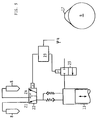
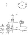
- FIGS. 1 and 2 for better comparison, the same or corresponding parts are drawn with the same reference numerals for the sake of a better comparison.
- the cylinder head with 1 As parts of the 4-stroke internal combustion engine, which is in particular a diesel engine, the cylinder head with 1, the engine housing with 2, the crankcase with 3, the crankshaft with 4, the cylinder with 5, and the pistons acting therein, connected to the crankshaft 4 via piston rods 6, are designated by 7. With 8 injection valves are designated, which inject the fuel directly into the combustion chambers 9 and are each connected to an injection pump 11 via a fuel pressure line 10.
- the injection pump 11 is used in the form of a plug-in pump which is installed in a shaft 12 of the laterally correspondingly enlarged motor housing and whose pump pistons can be actuated by control cams 13 which are provided on a camshaft 14 arranged below the plug-in pump 11 .
- This camshaft can be driven from the crankshaft 4 via its own control drive, which is indicated by the partial circles 15, 16, in a ratio of 1: 2, i.e. with every second crankshaft revolution, a certain amount of fuel is injected into a combustion chamber 9 via an injection valve 8 at a specific point in time.
- the camshaft 14 and the associated control drive 15, 16 of the known internal combustion engine can be omitted because the control cams 17 and the associated base circle (s) 20 are provided directly on the crankshaft 4 of the internal combustion engine .
- these control cams 17 on crankshaft 4 must be assigned an injection pump of the type whose delivery is controlled by solenoid valves.
- a pump 11 and a solenoid valve 18 are required per cylinder 5. 3, however, a pump 11 and two solenoid valves 22, 23 are required to control the injection into two cylinders 5.
- the situation in the case of FIG. 4 is even more favorable, since only one pump 11 and three solenoid valves 24, 25, 26 are required for controlling the injection into four cylinders 5.
- An electronic, computer-assisted regulating and control device 19 which has a microprocessor, data and program memory and an input and output periphery, which controls components internally, controls the solenoid valves 18 or 22, 23 or 24, 25, 26 a corresponding data bus system are linked together.
- the regulating and control device 19 is continuously supplied with the sensor-detected angle of rotation Kurbel of the crankshaft 4 as a control reference signal, on the basis of which the control of the existing solenoid valves is also regulated in the sense of variable control times by means of a program.
- a control cam 17 is required on the camshaft 4 per cylinder 5 for controlling an associated pump piston of the injection pump 11, but an injection per cylinder 5 takes place only every second crankshaft revolution.
- the second crankshaft revolution (360 - 720 ° Kw) is often also required for an injection, but for a different cylinder.
- an injection pump 11 with two solenoid valves 22, 23 is used for this purpose, the solenoid valve 22 being conveyed to a cylinder, e.g. Cylinder Z1, on delivery to another, e.g.
- Cylinder Z4 is switchable and therefore two engine cylinders can be supplied simultaneously with a cam 17 on the crankshaft side and a pump piston (as shown schematically in FIG. 3). While the solenoid valve 23 controls the delivery of the fuel, the solenoid valve 22 branches the delivered fuel alternately to two engine cylinders 5. This means that for the fuel injection, for example, a 4-cylinder internal combustion engine, an injection pump 11 with only two pump pistons, each with two solenoid valves 22 and two solenoid valves 23 are necessary.
- Fig. 4 shows such an example for a 4-cylinder in-line engine.
- the solenoid valve 26 controls the delivery of fuel
- the solenoid valve 25 distributes the delivery to a pair of cylinders
- the solenoid valve 24 distributes the delivery to the four cylinders alternately.
- the control cams 17 and the associated base circle (s) 20 can either be realized by appropriate shaping of crank cheek peripheral surfaces or on a control sleeve or a plurality of control disks, which are located within or is firmly attached to the crankshaft 4 outside.
- the control sleeve or the control disk (s) can be arranged outside the engine on a shaft section of the crankshaft 4 protruding there at the end, which allows smaller base circle diameters and also a fixed assignment of a normal injection pump equipped with the solenoid valves on the end of the engine.
- control cams 17 and the associated base circle (s) 20 are realized on crankshaft circumferential surfaces or are provided on control disks or a control sleeve attached to the crankshaft 4 within the engine, as shown in FIG. 1 can be seen - an insertion pump 11 for use, which is installed in an insertion shaft 21 opening into the interior of the crankcase 3.
Landscapes
- Engineering & Computer Science (AREA)
- Chemical & Material Sciences (AREA)
- Combustion & Propulsion (AREA)
- Mechanical Engineering (AREA)
- General Engineering & Computer Science (AREA)
- Fuel-Injection Apparatus (AREA)
Abstract
Description
- Die Erfindung betrifft eine Steuernocken-Anordnung zur Steuerung der Pumpenkolben einer Einspritzpumpe einer 4-Takt-Brennkraftmaschine, insbesondere 4-Takt-Dieselmotor.
- Für den Betrieb eines 4-Takt-Dieselmotors wird bekannterweise eine Einspritzanlage benötigt, die bei jeder zweiten Kurbelwellenumdrehung zu einem bestimmten Zeitpunkt eine bestimmte Kraftstoffmenge in einen Brennraum einspritzt. Bekannt sind hierzu folgende Konzepte:
- 1. Einspritzpumpen mit einer eigenen Nockenwelle oder Nockenscheibe (Reihen- und Verteilerpumpen),
- 2. Pumpendüsen oder Einsteckpumpen, deren Pumpenkolben von zusätzlich an einer Motornockenwelle angeordneten Einspritznocken getätigt werden, und
- 3. Pumpendüsen oder Einsteckpumpen, deren Pumpenkolben von einer nur Einspritznocken aufweisenden separaten Nockenwelle im Motor betätigt werden.
- Die für die Steuerung der Pumpenkolben zuständige Antriebswelle läuft dabei immer mit halber Motordrehzahl.
- Es ist daher Aufgabe der Erfindung, eine Steuernocken-Anordnung zur Steuerung der Pumpenkolben einer Einspritzpumpe einer 4-Takt-Brennkraftmaschine zu schaffen, die erheblich zur Herstellkostenreduzierung der Brennkraftmaschine beiträgt.
- Diese Aufgabe ist erfindungsgemäß dadurch gelöst, daß die den/die Pumpenkolben betätigenden Steuernocken und der/die zugehörige(n) Grundkreis(e) an der Kurbelwelle der Brennkraftmaschine gegeben sind und als Einspritzpumpe eine solche verwendet ist, deren Förderung durch Magnetventile gesteuert ist.
- Vorteilhafte Ausgestaltungen dieser Lösung sind in den Unteransprüchen angegeben.
- Aufgrund der erfindungsgemäßen Lösung ergeben sich folgende Vorteile:
- 1. Entfall eines gesonderten Einspritzpumpenantriebes.
- 2. Durch die größere Drehzahl und den größeren Nockengrundkreis lassen sich erheblich höhere Fördergeschwindigkeiten erreichen.
- 3. Die Drehschwingungs- und Geräuschanregung ist wesentlich geringer als bei bekannten Konzepten.
- 4. Die Nockenform ist wegen der großen Radien und damit geringen Hertz'schen Pressung über den vollen Kolbenhub nutzbar.
- 5. Es ergibt sich eine Herstellkostenreduzierung für die Brennkraftmaschine aufgrund des Entfalls eines gesonderten Einspritzpumpenantriebes.
- Nachstehend ist die erfindungsgemäße Lösung anhand der Zeichnung noch näher erläutert. In der Zeichnung zeigen:
- Fig. 1
- schematisch eine 4-Takt-Brennkraftmaschine mit einem ersten Ausführungsbeispiel der erfindungsgemäßen Lösung, mit Einsteckpumpe, deren Pumpenkolben von der Kurbelwelle aus betätigtwerden,
- Fig. 2
- zum Vergleich hierzu eine 4-Takt-Brennkraftmaschine bekannter Bauart, mit Einsteckpumpe, deren Pumpenkolben von einer eigens dafür im Motor vorgesehenen Nockenwelle betätigt werden,
- Fig. 3 und 4
- schematisch je eine weitere Ausführungsform der Erfindung für eine 4-zylindrige 4-Takt-Brennkraftmaschine.
- In Figuren 1 und 2 sind des besseren Vergleiches wegen gleiche bzw. einander entsprechende Teile mit gleichen Bezugszeichen angezogen.
- Als Teile der 4-Takt-Brennkraftmaschine, bei der es sich insbesondere um einen Dieselmotor handelt, sind in der Zeichnung der Zylinderkopf mit 1,das Motorgehäuse mit 2, das Kurbelgehäuse mit 3, die Kurbelwelle mit 4, die Zylinder mit 5, und die darin wirkenden, über Kolbenstangen 6 an der Kurbelwelle 4 angeschlossenen Kolben mit 7 bezeichnet. Mit 8 sind Einspritzventile bezeichnet, die den Kraftstoff direkt in die Brennräume 9 einspritzen und jeweils über eine Kraftstoffdruckleitung 10 mit einer Einspritzpumpe 11 verbunden sind.
- Im Vergleichsbeispiel gemäß Fig. 2 kommt die Einspritzpumpe 11 in Form einer Einsteckpumpe zur Anwendung, die in einen Schacht 12 des seitlich entsprechend erweiterten Motorgehäuses eingebaut ist und deren Pumpenkolben durch Steuernocken 13 betätigbar sind, die an einer unterhalb der Einsteckpumpe 11 angeordneten Nockenwelle 14 gegeben sind. Diese Nockenwelle ist von der Kurbelwelle 4 her über einen eigenen Steuertrieb, der durch die Teilkreise 15, 16 angedeutet ist, im Verhältnis 1 : 2 antreibbar, d.h. bei jeder zweiten Kurbelwellenumdrehung wird zu einem bestimmten Zeitpunkt eine bestimmte Kraftstoffmenge über ein Einspritzventil 8 in einen Brennraum 9 eingespritzt.
- Im Vergleich hierzu kann bei der erfindungsgemäßen Lösung die Nockenwelle 14 und der zugehörige Steuerungstrieb 15, 16 der bekannten Brennkraftmaschine deswegen entfallen, weil die Steuernocken 17 und der/die zugehörige(n) Grundkreis(e) 20 direkt an der Kurbelwelle 4 der Brennkraftmaschine gegeben sind. Da jedoch je Zylinder eine Einspritzung nur bei jeder zweiten Kurbelwellenumdrehung stattfinden darf, muß diesen an der Kurbelwelle 4 gegebenen Steuernocken 17 eine Einspritzpumpe solchen Typs zugeordnet sein, deren Förderung durch Magnetventile gesteuert wird.
- Im Fall gemäß Fig. 1 sind eine Pumpe 11 und ein Magnetventil 18 je Zylinder 5 erforderlich. Im Fall gemäß Fig. 3 sind dagegen sind eine Pumpe 11 und zwei Magnetventile 22, 23 zur Steuerung der Einspritzung in zwei Zylinder 5 notwendig. Noch günstiger sind die Verhältnisse im Fall gemäß Fig. 4, denn dort sind nur eine Pumpe 11 und drei Magnetventile 24, 25, 26 für die Steuerung der Einspritzung in vier Zylinder 5 erforderlich.
- Für die Steuerung der Magnetventile 18 bzw. 22, 23 bzw. 24, 25, 26 sorgt eine elektronische, rechnergestützt arbeitende Regel- und Steuereinrichtung 19, die einen Mikroprozessor, Daten- und Programmspeicher sowie eine Ein- und Ausgabeperipherie aufweist, welche Komponenten intern durch ein entsprechendes Datenbussystem miteinander verknüpft sind. Die Regel- und Steuereinrichtung 19 erhält fortlaufend den sensormäßig erfaßten Drehwinkel Φ der Kurbelwelle 4 als Steuerungsbezugssignal zugeführt, anhand dessen per Programm die Steuerung der vorhandenen Magnetventile auch im Sinne variabler Steuerzeiten geregelt wird.
- Im Fall gemäß Fig. 1 ist an der Nockenwelle 4 je Zylinder 5 ein Steuernocken 17 zur Steuerung eines zugehörigen Pumpenkolbens der Einspritzpumpe 11 notwendig, eine Einspritzung je Zylinder 5 erfolgt aber nur bei jeder zweiten Kurbelwellenumdrehung. Bei Mehrzylindermotoren, insbesondere 4-, 6- und 8-Zylindermotoren, wird jedoch häufig auch die zweite Kurbelwellenumdrehung (360 - 720° Kw) für eine Einspritzung benötigt, allerdings für einen anderen Zylinder. Bei der Ausführungsform gemäß Fig. 3 kommt hierfür eine Einspritzpumpe 11 mit zwei Magnetventilen 22, 23 zur Anwendung, wobei das Magnetventil 22 von Förderung zum einen Zylinder, z.B. Zylinder Z1, auf Förderung zu einem anderen, z.B. Zylinder Z4, umschaltbar ist und daher mit einer kurbelwellenseitigen Nocke 17 und einem Pumpenkolben (wie in Fig. 3 schematisch dargestellt) gleichzeitig zwei Motorzylinder versorgbar sind. Während das Magnetventil 23 die Förderung des Kraftstoffes steuert, verzweigt das Magnetventil 22 alternierend den geförderten Kraftstoff zu zwei Motorzylindern 5. Dieses bedeutet, daß für die Kraftstoffeinspritzung beispielsweise einer 4-Zylinder-Reihenbrennkraftmaschine eine Einspritzpumpe 11 mit nur zwei Pumpenkolben mit je zwei Magnetventilen 22 und je zwei Magnetventilen 23 notwendig ist.
- In Weiterbildung dieser Lösung können mit einem Pumpenkolben aber auch drei, vier oder sechs Zylinder mit Kraftstoff versorgt werden. Fig. 4 zeigt solches beispielhaft für einen 4-Zylinder-Reihenmotor. Hierzu sind zwei Nockenerhebungen je Kurbelwellenumdrehung notwendig, siehe die beiden Nocken 17 an der Nockenwelle 4. Durch diese Konfiguration wird eine Einspritzpumpe 11 mit nur einem Pumpenkolben für vier Zylinder 5 erforderlich sowie die drei Magnetventile 24, 25, 26. Das Magnetventil 26 steuert die Förderung des Kraftstoffes, das Magnetventil 25 verteilt die Förderung auf ein Zylinderpaar und das Magnetventil 24 verteilt die Förderung auf die vier Zylinder jeweils alternierend.
- Die Steuernocken 17 und der/die zugehörige(n) Grundkreis(e) 20 können entweder durch entsprechende Formgebung von Kurbelwangen-Umfangsflächen oder an einer Steuerhülse oder mehreren Steuerscheiben realisiert sein, die innerhalb oder außerhalb fest auf der Kurbelwelle 4 befestigt ist bzw. sind. Beispielsweise kann die Steuerhülse bzw. können die Steuerscheibe(n) außerhalb des Motors an einem dort stirnseitig herausragenden Wellenabschnitt der Kurbelwelle 4 angeordnet sein, was kleinere Grundkreis-Durchmesser und auch eine stirnseitig des Motors feste Zuordnung einer normalen, mit den Magnetventilen ausgestatteten Einspritzpumpe erlaubt. Für den Fall, daß die Steuernocken 17 und der/die Zugehörige(n) Grundkreis(e) 20 an Kurbelwangen-Umfangsflächen realisiert oder an innerhalb des Motors an der Kurbelwelle 4 befestigten Steuerscheiben bzw. einer Steuerhülse gegeben sind, kommt - wie aus Fig. 1 ersichtlich - eine Einsteckpumpe 11 zur Anwendung, die in einen, in den Innenraum des Kurbelgehäuses 3 ausmündenden Einsteckschacht 21 eingebaut ist.
Claims (7)
- Steuernocken-Anordnung zur Steuerung der Pumpenkolben einer Einspritzpumpe einer 4-Takt-Brennkraftmaschine, insbesondere Dieselmotor, dadurch gekennzeichnet, daß der/die Steuernocken (17) und der/die zugehörige(n) Grundkreis(e) (20) an der Kurbelwelle (4) der Brennkraftmaschine gegeben sind und als Einspritzpumpe (11) eine solche verwendet ist, deren Förderung durch Magnetventile (18 bzw. 22, 23 bzw. 24, 25, 26) gesteuert ist.
- Steuernocken-Anordnung nach Anspruch 1, dadurch gekennzeichnet, daß der/die Steuernocken (17) und der/die zugehörige(n) Grundkreis(e) (20) durch entsprechende Formgebung von Kurbelwangen-Umfangsflächen realisiert sind.
- Steuernocken-Anordnung nach Anspruch 1, dadurch gekennzeichnet, daß der/die Steuernocken (17) und der/die zugehörige(n) Grundkreis(e) (20) an einer oder mehreren fest auf der Kurbelwelle (4) innerhalb oder außerhalb des Motors befestigten Steuerscheibe(n) realisiert sind.
- Steuernocken-Anordnung nach Anspruch 1, dadurch gekennzeichnet, daß der/die Steuernocken (17) und der/die zugehörige(n) Grundkreis(e) (20) an einer fest auf der Kurbelwelle (4) innerhalb oder außerhalb des Motorgehäuses (3) befestigten Steuerhülse realisiert sind.
- Steuernocken-Anordnung nach einem der vorhergehenden Ansprüche, dadurch gekennzeichnet, daß der/die von den kurbelwellenseitig gegebenen Steuernocken (17) betätigbare(n) Pumpenkolben Teil(e) einer Einsteckpumpe (11) ist/sind, die in einen, in den Innenraum des Kurbelgehäuses (3) ausmündenden Einsteckschacht (21) eingebaut ist.
- Steuernocken-Anordnung nach einem der Ansprüche 3 und 4, dadurch gekennzeichnet, daß in dem Fall, wenn der/die Steuernocken (17) und der/die zugehörige(n) Grundkreis(e) (20) an der Kurbelwelle (4) an einem außerhalb des Motors gegebenen Kurbelwellenabschnitt angeordnet sind, die mit Magnetventilen (18 bzw. 22, 23 bzw. 24, 25, 26) ausgestattete Einspritzpumpe (11) dort stirnseitig am Motor befestigt ist.
- Steuernocken-Anordnung nach Anspruch 1, dadurch gekennzeichnet, daß zur Steuerung der Magnetventile (18 bzw. 22, 23 bzw. 24, 25, 26) der Einspritzpumpe (11) eine elektronische, rechnergestützt arbeitende Regel- und Steuereinrichtung (19) vorgesehen ist, die einen Mikroprozessor, Daten- und Programmspeicher, Ein- und Ausgabeperipherie - miteinander verknüpft über ein Datenbussystem - aufweist und als Arbeitsbasis fortlaufend den sensormäßig erfaßten Drehwinkel (Φ₄) der Kurbelwelle (4) zugeführt bekommt.
Applications Claiming Priority (2)
| Application Number | Priority Date | Filing Date | Title |
|---|---|---|---|
| AT1924/92 | 1992-09-29 | ||
| AT192492 | 1992-09-29 |
Publications (2)
| Publication Number | Publication Date |
|---|---|
| EP0590362A1 true EP0590362A1 (de) | 1994-04-06 |
| EP0590362B1 EP0590362B1 (de) | 1996-10-23 |
Family
ID=3523969
Family Applications (1)
| Application Number | Title | Priority Date | Filing Date |
|---|---|---|---|
| EP93114386A Expired - Lifetime EP0590362B1 (de) | 1992-09-29 | 1993-09-08 | Steuernocken-Anordnung zur Steuerung der Pumpenkolben einer Einspritzpumpe einer 4-Takt-Brennkraftmaschine |
Country Status (2)
| Country | Link |
|---|---|
| EP (1) | EP0590362B1 (de) |
| DE (1) | DE59304284D1 (de) |
Cited By (11)
| Publication number | Priority date | Publication date | Assignee | Title |
|---|---|---|---|---|
| DE19654286A1 (de) * | 1996-12-27 | 1998-07-02 | Dolmar Gmbh | Antriebsvorrichtung für eine Motorsense |
| DE19654290A1 (de) * | 1996-12-27 | 1998-07-02 | Dolmar Gmbh | Antriebsvorrichtung für einen Rasentrimmer |
| GB2338512A (en) * | 1998-06-15 | 1999-12-22 | Caterpillar Inc | Reciprocating-piston i.c. engine with integral piston pump |
| US6007305A (en) * | 1996-12-19 | 1999-12-28 | Caterpillar Inc. | Internal combustion engine with integral crankshaft driven pump |
| EP2342449A1 (de) * | 2008-10-16 | 2011-07-13 | Continental Automotive GmbH | Einspritzanlage für eine brennkraftmaschine |
| DE102010016356A1 (de) * | 2010-04-07 | 2011-10-13 | A. T. Süd GmbH | Verbrennungskraftmaschine mit Kraftstoffpumpe |
| EP2375030A3 (de) * | 2010-04-07 | 2012-02-15 | A. T. Süd GmbH | Verbrennungskraftmaschine mit Kraftstoffpumpe |
| EP2529102A2 (de) * | 2010-01-29 | 2012-12-05 | BRP-Powertrain GmbH & Co. KG | Kraftstoffversorgungssystem für einen verbrennungsmotor |
| WO2014044438A1 (de) * | 2012-09-18 | 2014-03-27 | Robert Bosch Gmbh | Brennkraftmaschine mit einem kurbelgehäuse |
| WO2016055247A1 (de) * | 2014-10-08 | 2016-04-14 | Continental Automotive Gmbh | ROLLE FÜR EINEN ROLLENSTÖßEL EINER KRAFTSTOFFHOCHDRUCKPUMPE, ROLLENSTÖßEL, KRAFTSTOFFHOCHDRUCKPUMPE UND BRENNKRAFTMASCHINE |
| GB2540584A (en) * | 2015-07-22 | 2017-01-25 | Gm Global Tech Operations Llc | Internal combustion engine comprising a fuel unit pump actuated by the crankshaft |
Families Citing this family (1)
| Publication number | Priority date | Publication date | Assignee | Title |
|---|---|---|---|---|
| CN101333935B (zh) * | 2007-06-26 | 2010-08-25 | 粘育珲 | 动力装置 |
Citations (5)
| Publication number | Priority date | Publication date | Assignee | Title |
|---|---|---|---|---|
| GB495246A (en) * | 1938-02-03 | 1938-11-09 | Johannes Olsson | Improvements in the valve gear of reciprocating engines |
| FR849794A (fr) * | 1938-02-03 | 1939-12-01 | Brandenburgische Motorenwerke | Moteur à combustion interne à quatre temps travaillant suivant le procédé à explosion avec charge et injection de combustible |
| JPS6079159A (ja) * | 1983-10-07 | 1985-05-04 | Mitsui Eng & Shipbuild Co Ltd | 燃料噴射式内燃機関 |
| JPS63201370A (ja) * | 1987-02-18 | 1988-08-19 | Mitsubishi Heavy Ind Ltd | 内燃機関用燃料供給装置 |
| EP0408915A1 (de) * | 1989-07-20 | 1991-01-23 | Robert Bosch Gmbh | Kraftstoffeinspritzpumpe für Brennkraftmaschinen |
Family Cites Families (1)
| Publication number | Priority date | Publication date | Assignee | Title |
|---|---|---|---|---|
| DE4019586A1 (de) * | 1990-06-20 | 1992-01-02 | Bosch Gmbh Robert | Kraftstoffeinspritzsystem fuer brennkraftmaschinen |
-
1993
- 1993-09-08 EP EP93114386A patent/EP0590362B1/de not_active Expired - Lifetime
- 1993-09-08 DE DE59304284T patent/DE59304284D1/de not_active Expired - Fee Related
Patent Citations (5)
| Publication number | Priority date | Publication date | Assignee | Title |
|---|---|---|---|---|
| GB495246A (en) * | 1938-02-03 | 1938-11-09 | Johannes Olsson | Improvements in the valve gear of reciprocating engines |
| FR849794A (fr) * | 1938-02-03 | 1939-12-01 | Brandenburgische Motorenwerke | Moteur à combustion interne à quatre temps travaillant suivant le procédé à explosion avec charge et injection de combustible |
| JPS6079159A (ja) * | 1983-10-07 | 1985-05-04 | Mitsui Eng & Shipbuild Co Ltd | 燃料噴射式内燃機関 |
| JPS63201370A (ja) * | 1987-02-18 | 1988-08-19 | Mitsubishi Heavy Ind Ltd | 内燃機関用燃料供給装置 |
| EP0408915A1 (de) * | 1989-07-20 | 1991-01-23 | Robert Bosch Gmbh | Kraftstoffeinspritzpumpe für Brennkraftmaschinen |
Non-Patent Citations (2)
| Title |
|---|
| PATENT ABSTRACTS OF JAPAN vol. 12, no. 484 (M - 776) 16 December 1988 (1988-12-16) * |
| PATENT ABSTRACTS OF JAPAN vol. 9, no. 220 (E - 341)<1943> 6 September 1985 (1985-09-06) * |
Cited By (13)
| Publication number | Priority date | Publication date | Assignee | Title |
|---|---|---|---|---|
| US6007305A (en) * | 1996-12-19 | 1999-12-28 | Caterpillar Inc. | Internal combustion engine with integral crankshaft driven pump |
| DE19654286A1 (de) * | 1996-12-27 | 1998-07-02 | Dolmar Gmbh | Antriebsvorrichtung für eine Motorsense |
| DE19654290A1 (de) * | 1996-12-27 | 1998-07-02 | Dolmar Gmbh | Antriebsvorrichtung für einen Rasentrimmer |
| US6196170B1 (en) | 1996-12-27 | 2001-03-06 | Dolmar Gmbh | Driving device for a lawn trimmer |
| GB2338512A (en) * | 1998-06-15 | 1999-12-22 | Caterpillar Inc | Reciprocating-piston i.c. engine with integral piston pump |
| EP2342449A1 (de) * | 2008-10-16 | 2011-07-13 | Continental Automotive GmbH | Einspritzanlage für eine brennkraftmaschine |
| EP2529102A2 (de) * | 2010-01-29 | 2012-12-05 | BRP-Powertrain GmbH & Co. KG | Kraftstoffversorgungssystem für einen verbrennungsmotor |
| EP2385237A2 (de) | 2010-04-07 | 2011-11-09 | A. T. Süd GmbH | Verbrennungskraftmaschine mit Kraftstoffpumpe |
| EP2375030A3 (de) * | 2010-04-07 | 2012-02-15 | A. T. Süd GmbH | Verbrennungskraftmaschine mit Kraftstoffpumpe |
| DE102010016356A1 (de) * | 2010-04-07 | 2011-10-13 | A. T. Süd GmbH | Verbrennungskraftmaschine mit Kraftstoffpumpe |
| WO2014044438A1 (de) * | 2012-09-18 | 2014-03-27 | Robert Bosch Gmbh | Brennkraftmaschine mit einem kurbelgehäuse |
| WO2016055247A1 (de) * | 2014-10-08 | 2016-04-14 | Continental Automotive Gmbh | ROLLE FÜR EINEN ROLLENSTÖßEL EINER KRAFTSTOFFHOCHDRUCKPUMPE, ROLLENSTÖßEL, KRAFTSTOFFHOCHDRUCKPUMPE UND BRENNKRAFTMASCHINE |
| GB2540584A (en) * | 2015-07-22 | 2017-01-25 | Gm Global Tech Operations Llc | Internal combustion engine comprising a fuel unit pump actuated by the crankshaft |
Also Published As
| Publication number | Publication date |
|---|---|
| DE59304284D1 (de) | 1996-11-28 |
| EP0590362B1 (de) | 1996-10-23 |
Similar Documents
| Publication | Publication Date | Title |
|---|---|---|
| DE1751736C2 (de) | Mehrzylindrige Kraftstoffeinspritzpumpe für Brennkraftmaschinen | |
| EP0590362B1 (de) | Steuernocken-Anordnung zur Steuerung der Pumpenkolben einer Einspritzpumpe einer 4-Takt-Brennkraftmaschine | |
| DE19654570A1 (de) | Kettentrieb mit Zwischenwelle | |
| DE19624240C2 (de) | Brennkraftmaschine | |
| DE1576310B2 (de) | Mengenregeleinrichtung einer kraftstoffeinspritzpumpe fuer kraftfahrzeugdieselmotoren | |
| EP0622534A1 (de) | Brennkraftmaschine mit zwei Zylinderreihen | |
| DE19535963B4 (de) | System zur Abnahme von Leistung aus einer Kurbelwelle | |
| DE69917599T2 (de) | Nockenwellenkettentrieb für eine Brennkraftmaschine mit zwei obenliegenden Nockenwellen | |
| DE3540811C2 (de) | ||
| EP0624717B1 (de) | Brennkraftmaschine mit einer Nockenwellen-Antriebsverstelleinheit | |
| DE3204841A1 (de) | Hubkolben-brennkraftmaschine mit einer vorrichtung zur winkelverstellung der nockenwellen relativ zueinander | |
| EP0011611B1 (de) | Brennstoffeinspritzanlage für Einspritzbrennkraftmaschinen | |
| DE4017239A1 (de) | Nockenwelle | |
| DE3035244C2 (de) | Ventilgesteuerte Hubkolben-Brennkraftmaschine | |
| DE3500616A1 (de) | Brennstoff-einspritzpumpe fuer eine brennkraftmaschine | |
| DE10051977A1 (de) | Vorrichtung für einen Antrieb einer Hochdruckpumpe eines Kraftstoffeinspritzsystems | |
| DE19857555A1 (de) | Direkteinspritzende fremdgezündete Brennkraftmaschine | |
| DE10135127B4 (de) | Einrichtung zum Verändern des Verdichtungsverhältnisses von Kolbenmaschinen, insbesondere Hubkolbenbrennkraftmaschinen | |
| DE3832897A1 (de) | Verbrennungsmotor | |
| EP0027792A1 (de) | Einspritzpumpe für Einspritzbrennkraftmaschinen, insbesondere Dieselmotoren | |
| DE4037272A1 (de) | Hubkolben-brennkraftmaschine mit zwei zylinderreihen | |
| EP0615063B1 (de) | Kraftstoffeinspritzpumpe | |
| DE102017207399B4 (de) | Verfahren zum Betreiben einer Brennkraftmaschine und Brennkraftmaschine | |
| DE19832383A1 (de) | Ventilgesteuerter Mehrreihenmotor | |
| DE1576310C3 (de) | Mengenregeleinrichtung einer Kraftstoffeinspritzpumpe für Kraftfahrzeugdieselmotoren |
Legal Events
| Date | Code | Title | Description |
|---|---|---|---|
| PUAI | Public reference made under article 153(3) epc to a published international application that has entered the european phase |
Free format text: ORIGINAL CODE: 0009012 |
|
| 17P | Request for examination filed |
Effective date: 19931214 |
|
| AK | Designated contracting states |
Kind code of ref document: A1 Designated state(s): CH DE FR GB IT LI NL SE |
|
| 17Q | First examination report despatched |
Effective date: 19950330 |
|
| GRAG | Despatch of communication of intention to grant |
Free format text: ORIGINAL CODE: EPIDOS AGRA |
|
| GRAH | Despatch of communication of intention to grant a patent |
Free format text: ORIGINAL CODE: EPIDOS IGRA |
|
| ITF | It: translation for a ep patent filed | ||
| GRAH | Despatch of communication of intention to grant a patent |
Free format text: ORIGINAL CODE: EPIDOS IGRA |
|
| GRAA | (expected) grant |
Free format text: ORIGINAL CODE: 0009210 |
|
| AK | Designated contracting states |
Kind code of ref document: B1 Designated state(s): CH DE FR GB IT LI NL SE |
|
| REF | Corresponds to: |
Ref document number: 59304284 Country of ref document: DE Date of ref document: 19961128 |
|
| ET | Fr: translation filed | ||
| GBT | Gb: translation of ep patent filed (gb section 77(6)(a)/1977) |
Effective date: 19961206 |
|
| PLBE | No opposition filed within time limit |
Free format text: ORIGINAL CODE: 0009261 |
|
| PG25 | Lapsed in a contracting state [announced via postgrant information from national office to epo] |
Ref country code: LI Free format text: LAPSE BECAUSE OF NON-PAYMENT OF DUE FEES Effective date: 19970930 Ref country code: CH Free format text: LAPSE BECAUSE OF NON-PAYMENT OF DUE FEES Effective date: 19970930 |
|
| 26N | No opposition filed | ||
| REG | Reference to a national code |
Ref country code: CH Ref legal event code: PL |
|
| PGFP | Annual fee paid to national office [announced via postgrant information from national office to epo] |
Ref country code: GB Payment date: 19980814 Year of fee payment: 6 |
|
| PGFP | Annual fee paid to national office [announced via postgrant information from national office to epo] |
Ref country code: DE Payment date: 19980821 Year of fee payment: 6 Ref country code: FR Payment date: 19980821 Year of fee payment: 6 |
|
| PGFP | Annual fee paid to national office [announced via postgrant information from national office to epo] |
Ref country code: SE Payment date: 19980824 Year of fee payment: 6 |
|
| PGFP | Annual fee paid to national office [announced via postgrant information from national office to epo] |
Ref country code: NL Payment date: 19980827 Year of fee payment: 6 |
|
| PG25 | Lapsed in a contracting state [announced via postgrant information from national office to epo] |
Ref country code: GB Free format text: LAPSE BECAUSE OF NON-PAYMENT OF DUE FEES Effective date: 19990908 |
|
| PG25 | Lapsed in a contracting state [announced via postgrant information from national office to epo] |
Ref country code: SE Free format text: THE PATENT HAS BEEN ANNULLED BY A DECISION OF A NATIONAL AUTHORITY Effective date: 19990929 |
|
| PG25 | Lapsed in a contracting state [announced via postgrant information from national office to epo] |
Ref country code: NL Free format text: LAPSE BECAUSE OF NON-PAYMENT OF DUE FEES Effective date: 20000401 |
|
| GBPC | Gb: european patent ceased through non-payment of renewal fee |
Effective date: 19990908 |
|
| EUG | Se: european patent has lapsed |
Ref document number: 93114386.1 |
|
| PG25 | Lapsed in a contracting state [announced via postgrant information from national office to epo] |
Ref country code: FR Free format text: LAPSE BECAUSE OF NON-PAYMENT OF DUE FEES Effective date: 20000531 |
|
| NLV4 | Nl: lapsed or anulled due to non-payment of the annual fee |
Effective date: 20000401 |
|
| PG25 | Lapsed in a contracting state [announced via postgrant information from national office to epo] |
Ref country code: DE Free format text: LAPSE BECAUSE OF NON-PAYMENT OF DUE FEES Effective date: 20000701 |
|
| REG | Reference to a national code |
Ref country code: FR Ref legal event code: ST |
|
| PG25 | Lapsed in a contracting state [announced via postgrant information from national office to epo] |
Ref country code: IT Free format text: LAPSE BECAUSE OF NON-PAYMENT OF DUE FEES;WARNING: LAPSES OF ITALIAN PATENTS WITH EFFECTIVE DATE BEFORE 2007 MAY HAVE OCCURRED AT ANY TIME BEFORE 2007. THE CORRECT EFFECTIVE DATE MAY BE DIFFERENT FROM THE ONE RECORDED. Effective date: 20050908 |