EP0590437A1 - Appareil pour remplir des sacs de poudre, de granulés, notamment de sable - Google Patents
Appareil pour remplir des sacs de poudre, de granulés, notamment de sable Download PDFInfo
- Publication number
- EP0590437A1 EP0590437A1 EP93114979A EP93114979A EP0590437A1 EP 0590437 A1 EP0590437 A1 EP 0590437A1 EP 93114979 A EP93114979 A EP 93114979A EP 93114979 A EP93114979 A EP 93114979A EP 0590437 A1 EP0590437 A1 EP 0590437A1
- Authority
- EP
- European Patent Office
- Prior art keywords
- filler neck
- filling
- screw conveyor
- feed container
- sack
- Prior art date
- Legal status (The legal status is an assumption and is not a legal conclusion. Google has not performed a legal analysis and makes no representation as to the accuracy of the status listed.)
- Granted
Links
Images

Classifications
-
- B—PERFORMING OPERATIONS; TRANSPORTING
- B65—CONVEYING; PACKING; STORING; HANDLING THIN OR FILAMENTARY MATERIAL
- B65B—MACHINES, APPARATUS OR DEVICES FOR, OR METHODS OF, PACKAGING ARTICLES OR MATERIALS; UNPACKING
- B65B1/00—Packaging fluent solid material, e.g. powders, granular or loose fibrous material, loose masses of small articles, in individual containers or receptacles, e.g. bags, sacks, boxes, cartons, cans, or jars
- B65B1/04—Methods of, or means for, filling the material into the containers or receptacles
- B65B1/10—Methods of, or means for, filling the material into the containers or receptacles by rotary feeders
- B65B1/12—Methods of, or means for, filling the material into the containers or receptacles by rotary feeders of screw type
Definitions
- the invention relates to a device for filling sacks with a powdery, granular or granular filling material, in particular sand, with an in particular funnel-shaped feed container for the filling material, with a horizontal and electric motor-operated screw conveyor arranged in the bottom region of the feeding container and with a cantilevered and vertically protruding screw Angled filler neck of the feed container, in which the screw feeder opens and onto which the sack to be filled can be pushed, a switch being arranged in the push-on area of the filler neck for the respective sack to be filled, which can be actuated when the sack is pushed open and thereby triggers the filling process .
- a special field of application of the filling device according to the invention is the filling of sandbags.
- sandbags are used, for example, to build dams during floods.
- the filling device according to the invention is also suitable for other filling materials, namely powdery, granular or granular filling materials.
- US Pat. No. 3,867,970 discloses a device for mixing two materials, in particular cement and sand, and then filling them into corresponding filling containers of the type specified at the outset.
- feed containers are provided for the materials to be mixed, which are by means of a piston / cylinder unit pivotable flap are completed.
- the two feed containers open into a screw conveyor in the area of the bottom. This in turn opens into a filler neck that is angled vertically downwards and onto which the sack to be filled can be pushed.
- This filler neck has a bag clamping device in the slide-on area for the sack to be filled, which is in operative connection with a switch, this switch in turn in operative connection with an electromagnetic valve for the piston / cylinder unit.
- the screw conveyor is switched to continuous operation.
- the switch is actuated by the bag clamping device and by this the electromagnetic valve, which swivels open the flap by means of the piston / cylinder unit, so that the materials in the feed containers get into the screw conveyor and are mixed together there.
- the materials are simultaneously transported to the filler neck, from where they fall into the sack. After the sack has been removed, the flap is closed again and the filling process is ended.
- the object of the invention is to create an easy-to-handle filling device, in particular for sandbags, with which a high filling capacity is also possible.
- the invention proposes that the switch put the electric motor for the screw conveyor into operation and stop the electric motor again when the bag is removed.
- a filling device is created in particular for sandbags, which is easy to handle on the one hand and which works with a high filling capacity on the other hand.
- This is achieved according to the invention in that the opening of the sack is pushed from below onto the filler neck projecting vertically downwards.
- the switch that starts the electric motor for the screw conveyor is automatically activated. This switch can be operated by the upper edge of the bag and / or by the operator's hand.
- the filling process is started immediately. When the sack is then filled with the specified amount, it is pulled down from the filler neck.
- the switch returns to its inoperative position and thereby stops the motor for the screw conveyor, so that the supply of further filling material is interrupted.
- a further development of the filling device proposes that a first, cylindrical and horizontally projecting filler neck section is provided, into which the end of the screw conveyor protrudes, and that a second, also cylindrical filler neck section extends from the lateral surface of this first filler neck section.
- the filling material conveyed by means of the screw conveyor falls after passing through the first filling nozzle section into the second filling nozzle section down into the sack to be filled.
- screw conveyor has the same diameter over its entire length. This ensures that the filling material is conveyed into the filler neck without complications, without, for example, the filling material being compressed, which tends to become blocked.
- a further development of the filling device according to the invention proposes that a grate is provided below the filler neck for placing the sack to be filled in each case. This has the advantage that the operator does not have to hold the sack continuously during the entire filling process, but is relieved of the weight.
- the grate can preferably be folded up when not in use, so that the filling device can be easily transported from one place to another.
- a further development of the support grid suggests that it can be adjusted in height, for example by means of a plug-in mechanism, and thus can be adapted to different bag heights.
- a further preferred development of the filling device proposes that a trigger element which can be actuated by the hand of the operator is arranged on the filler neck and is operatively connected to the switch.
- a trigger element which can be actuated by the hand of the operator is arranged on the filler neck and is operatively connected to the switch.
- a further development of this suggests that two trigger elements are arranged on the filler neck, each of which is operatively connected to a switch, the two trigger elements being operable by one hand of the operator, and the electric motor for the screw conveyor can only be put into operation if both release elements can be operated simultaneously with both hands.
- the basic idea of this development using two trigger elements is that the operator must use both hands to start the electric motor and thus the screw conveyor when the bag is pushed onto the filler neck.
- Each of the two tripping elements thus actuates an electrical switch on its own, these two electrical switches being connected in series (AND circuit). Since the screw conveyor can thus only be operated with both hands, the operator is prevented from reaching into the filler neck from below and possibly injuring himself in the process. This increases security.
- the trigger element is preferably a trigger lever which can be pivoted about a horizontal axis. This is a technically simple way to operate the switch or the two switches.
- the trigger lever which is pivotably articulated about a horizontal axis, is pivoted upwards when the sack is pushed onto the filler neck, so that the switch is actuated and the screw conveyor is started. If the sack is removed from the filler neck after filling, the release lever returns to its starting position and interrupts the switch again. This pivoting back of the trigger lever can take place due to gravity, but also by the switch when it is spring-loaded and presses down on the trigger lever.
- this design of the release lever has the advantage that the filler neck is surrounded almost around its entire circumference by an actuation stop in the form of the horseshoe-shaped release lever for actuating the switch, so that when the sack to be filled is pushed open, it is in any case the switch is operated.
- a further development of the feed container suggests that it has a vibration device. Moist sands can also be conveyed in this way, since the vibrating device ensures that the sand settles in the bottom area of the feed container, thus ensuring that the screw conveyor is always replenished.
- a further development of the filling device proposes that the feed container be covered by a sieve-like grid.
- This prevents stones from entering the feed container, for example with sand, which could lead to a malfunction when the feed container is filled.
- this sieve-like grille can be folded up so that the inside of the feed container is freely accessible.
- the fold-up grille is operatively connected to a switch in such a way that the electric motor is switched off in any case when the grid is folded up, in order to prevent the risk of toppling over.
- the grid is firmly connected to the feed container without it can be easily removed.
- the sieve-like grille is screwed to the feed container.
- a further preferred development of the feed container suggests that an extension attachment can optionally be placed thereon.
- This add-on container which can be placed on the feed container serves to increase the volume, for example for mechanical filling by means of a shovel loader or excavator. If the feed container is provided with such an extension attachment, then the sieve-like grid is no longer arranged on the actual feed container, but on the extension attachment. So that the vibration energy is optimally transmitted to the extension attachment when using a vibration device, it must be firmly connected to the feed container, for example screwed to the feed container.
- the filling device according to the invention it is proposed that it be designed laterally in such a way that several of these filling devices can be aligned side by side and define a closed feed surface for the filling material.
- the individual filling devices can thus be put together in modules to form a larger unit.
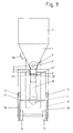
- the filling device has a funnel-shaped feed container 1 with a V-shaped cross section.
- An extension attachment 1 ' is placed on this feed container 1 and firmly connected to the feed container 1, for example by screwing.
- a screw conveyor 2 extends along the apex line, which is rotatably supported with its shaft 3 in the feed container 1 on the end face.
- an electric motor 4 is provided which drives the shaft 3 of the screw conveyor 2 via a belt 5.
- the screw conveyor 2 protrudes into a filler neck 6, which is arranged on the end of the feed container 1 in a projecting manner on the end thereof.
- the filler neck 6 consists of a first filler neck section 6 ′ which is arranged on the feed container 1 in a projecting manner.
- the shaft 3 of the screw conveyor 2 is rotatably mounted in a final end wall 7 of this first filler neck section 6 '.
- a second, likewise cylindrical, filler neck section 6 ′′ extends vertically downward from the lateral surface 8 of the first filler neck section 6 ′ and is open at the bottom.
- the filler neck 6 is thus angularly formed by the two filler neck sections 6 ', 6' '.
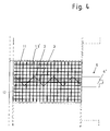
- the top of the extension attachment 1 ' is covered by a sieve-shaped grating 11 which can be pivoted upwards and is in operative connection with a switch 12. Instead of the pivoting of the grid 11, this can also be fixedly attached to the extension attachment 1 'or - if the extension attachment 1' is missing - to the feed container 1.
- the feed container 1 with all of its described additional devices is mounted on a frame 13.
- This has rollers 14 at one end.
- the frame 13 has handles 15 that can be folded up.
- the frame 13 has height-adjustable support legs 16 in the region of the handles 15, which allow adaptation to uneven floors.
- the operating height of the sandbag filling device can be changed by the height-adjustable support legs 16.
- the frame 13 below the filler neck 6 has a grate 17 which can be folded up for the filling device when it is not in use.
- the grate 17 is adjustable in height, so that an easy adaptation to different sack heights is possible.
- the filling device works as follows: First of all, the filling device can be easily moved by hand to the place of use by folding the handles 15 upward, so that the operator can lift the filling device and move it on the rollers 14. At the place of use, to increase the stability, the support legs 16 are extended if necessary and the grate 17 is folded down and its height is adjusted depending on the size of the bags to be filled. The grid 11 is also in the lower position. The filling material, in particular sand, is then fed from the top of the feed container 1 with its extension attachment 1 'through the grid 11, the grid 11 holding back large stones which do not fall through the mesh of the grid 11. The feed container 1 or the extension attachment 1 'can be loaded with the filling material up to the upper edge.
- the sack 18 to be filled is then pushed from below onto the second filler neck section 6 ′′ and lies on the grate 17.
- the two release levers 10, 10 ′ are pivoted upward by the two hands of the operator such that the two switches 9, 9 ′ are actuated. Only when both switches 9, 9 'are actuated is the electric motor 4 and thus the screw conveyor 2 set in motion, so that the filling material is transported within the feed container 1 to the filling nozzle 6.
- the filling material falls down into the sack 18 through the second filling nozzle section 6 ′′ which points vertically downwards, so that the latter gradually fills up.
- the operator slides the sack 18 down from the second filling nozzle section 6 ′′, so that the release levers 10, 10 ′ also (due to gravity and / or due to the spring loading of the switches 9, 9 ′ ) Swing down again and do not operate the switches 9, 9 'anymore, so that the electric motor 4 is switched off and no further conveyance of the filling material takes place. Since both hands are required to actuate the electric motor 4, the operator is prevented from getting into the second filler neck section 6 ′′ from below with one hand. This eliminates the risk of injury.
- the grille 11 is operatively connected to a switch 12 in such a way that when the grille 11 is folded up, the electric motor 4 and thus the drive of the screw conveyor 2 is definitely interrupted in order to reduce the risk of accidents, for example when rotating Screw conveyor 2 someone would get into the feed container 1 or into the extension attachment 1 '.
- the feed container 1 has a vibrating device 19 on the side. By shaking this vibrating device, the sand continuously slips in the feed container 1, so that a feed jam cannot occur.
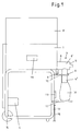
- Fig. 4 is indicated by dashed lines that several filling devices can be strung together, which are flush with each other for this purpose laterally.
- the filling devices can be assembled into a larger unit, which has the advantage that this unit can be loaded with the filling material by means of a single bucket load of an excavator.
Landscapes
- Engineering & Computer Science (AREA)
- Mechanical Engineering (AREA)
- Basic Packing Technique (AREA)
Applications Claiming Priority (2)
| Application Number | Priority Date | Filing Date | Title |
|---|---|---|---|
| DE4232398A DE4232398C2 (de) | 1992-09-26 | 1992-09-26 | Vorrichtung zum Befüllen von Säcken mit einem pulverförmigen, körnigen oder granulatförmigen Füllgut, insbesondere Sand |
| DE4232398 | 1992-09-26 |
Publications (2)
| Publication Number | Publication Date |
|---|---|
| EP0590437A1 true EP0590437A1 (fr) | 1994-04-06 |
| EP0590437B1 EP0590437B1 (fr) | 1996-01-31 |
Family
ID=6468979
Family Applications (1)
| Application Number | Title | Priority Date | Filing Date |
|---|---|---|---|
| EP93114979A Expired - Lifetime EP0590437B1 (fr) | 1992-09-26 | 1993-09-17 | Appareil pour remplir des sacs de poudre, de granulés, notamment de sable |
Country Status (3)
| Country | Link |
|---|---|
| EP (1) | EP0590437B1 (fr) |
| AT (1) | ATE133624T1 (fr) |
| DE (2) | DE4232398C2 (fr) |
Families Citing this family (4)
| Publication number | Priority date | Publication date | Assignee | Title |
|---|---|---|---|---|
| DE4427102A1 (de) * | 1994-07-30 | 1996-02-01 | Kupczik Guenter | Verfahren und Vorrichtung zum Befüllen mit Schüttgut und Schließen von Säcken |
| DE19644038A1 (de) * | 1996-10-31 | 1998-05-20 | Alfred Lachner | Sandsackfüllgerät |
| DE10305559A1 (de) * | 2003-02-10 | 2004-08-26 | Albert Horn | Sandsackabfüllvorrichtung |
| DE202004003480U1 (de) | 2004-03-03 | 2004-04-29 | Saquick Gmbh | Befüllvorrichtung, insbesondere für Sandsäcke |
Citations (4)
| Publication number | Priority date | Publication date | Assignee | Title |
|---|---|---|---|---|
| DE1486047A1 (de) * | 1965-01-08 | 1969-02-13 | Michael Siegburg | Vorrichtung zum Abfuellen von Getreide od.dgl. koernigen Guetern in Saecke |
| US3867970A (en) * | 1973-12-14 | 1975-02-25 | Sr James E Winchester | Mixing and bagging machine for dry mixes |
| DE2740178A1 (de) * | 1976-10-05 | 1978-04-06 | Sig Schweiz Industrieges | Einrichtung zum dosieren von schuettbaren guetern |
| DE3441409A1 (de) * | 1984-11-13 | 1986-05-22 | Elba-Werk Maschinen-Gesellschaft Mbh & Co, 7505 Ettlingen | Verfahren zum betreiben einer austragsvorrichtung |
Family Cites Families (2)
| Publication number | Priority date | Publication date | Assignee | Title |
|---|---|---|---|---|
| DE927012C (de) * | 1942-01-23 | 1955-04-28 | Mario Tamini | Verfahren und Vorrichtung zur gleichzeitigen Fuellung mehrerer Behaelter fuer Zement und anderes loses Gut |
| DE1230711B (de) * | 1961-11-20 | 1966-12-15 | Hesser Ag Maschf | Vorrichtung zum Fuellen von Verpackungsbehaeltern mit abgemessenen Mengen eines fliessfaehigen Schuettgutes |
-
1992
- 1992-09-26 DE DE4232398A patent/DE4232398C2/de not_active Expired - Fee Related
-
1993
- 1993-09-17 DE DE59301545T patent/DE59301545D1/de not_active Expired - Fee Related
- 1993-09-17 EP EP93114979A patent/EP0590437B1/fr not_active Expired - Lifetime
- 1993-09-17 AT AT93114979T patent/ATE133624T1/de not_active IP Right Cessation
Patent Citations (4)
| Publication number | Priority date | Publication date | Assignee | Title |
|---|---|---|---|---|
| DE1486047A1 (de) * | 1965-01-08 | 1969-02-13 | Michael Siegburg | Vorrichtung zum Abfuellen von Getreide od.dgl. koernigen Guetern in Saecke |
| US3867970A (en) * | 1973-12-14 | 1975-02-25 | Sr James E Winchester | Mixing and bagging machine for dry mixes |
| DE2740178A1 (de) * | 1976-10-05 | 1978-04-06 | Sig Schweiz Industrieges | Einrichtung zum dosieren von schuettbaren guetern |
| DE3441409A1 (de) * | 1984-11-13 | 1986-05-22 | Elba-Werk Maschinen-Gesellschaft Mbh & Co, 7505 Ettlingen | Verfahren zum betreiben einer austragsvorrichtung |
Also Published As
| Publication number | Publication date |
|---|---|
| DE59301545D1 (de) | 1996-03-14 |
| EP0590437B1 (fr) | 1996-01-31 |
| DE4232398A1 (de) | 1994-03-31 |
| ATE133624T1 (de) | 1996-02-15 |
| DE4232398C2 (de) | 1995-04-27 |
Similar Documents
| Publication | Publication Date | Title |
|---|---|---|
| DE1556516C3 (de) | Vorrichtung zum kontinuierlichen oder diskontinuierlichen Beladen des Ladebehälters eines Müllfahrzeuges | |
| DE4234518C2 (de) | Materialmahlvorrichtung mit einer Materialmahltrommel und Scherstäben | |
| DE69301148T2 (de) | Vorrichtung zum verpacken von produkten in beutel | |
| EP0590437B1 (fr) | Appareil pour remplir des sacs de poudre, de granulés, notamment de sable | |
| DE3914459A1 (de) | Vorrichtung zum entleeren von mit schuettgut gefuellten saecken | |
| DE2037447A1 (de) | Vorrichtung zur schnellen Entleerung großer Kornbehälter in Mähdreschern Arim Clayson N V, Zeäelgem (Belgien) | |
| CH564467A5 (en) | Equipment for filling and compressing garbage - has arrangement for alternately opening feeder and compressing garbage | |
| DE3305383C2 (de) | Vorsieb zum Trennen von Mischabfällen und Verfahren zum Betrieb des Vorsiebs | |
| DE1267615B (de) | Vorrichtung zum Aufschlitzen und Entleeren von Saecken | |
| DE4014462A1 (de) | Vorrichtung zum auflockern von schuettgut | |
| DE9006661U1 (de) | Vorrichtung zum Eintragen und bzw. oder zum Austragen von Schüttgut | |
| DE2527959A1 (de) | Muellpressanlage | |
| DE2841309A1 (de) | Dosierwaage fuer futtermittel o.dgl. | |
| DE1910951C (de) | Vorrichtung zum Aufnehmen und Einsacken von Schüttgut | |
| DE1261445B (de) | Einrichtung zum selbsttaetigen UEberfuehren von Zigaretten oder anderen stabfoermigen Gegenstaenden von einer Fertigungsmaschine zu einer diese Gegenstaende weiterverarbeitenden Maschine | |
| DE29511710U1 (de) | Sammel- und Mischvorrichtung für Silage | |
| EP2228304B1 (fr) | Dispositif destiné à remplir des sacs | |
| DE1781271C (de) | Vorrichtung zur Aufbereitung und Weiterleitung von kornigem, festem Material aus stationären Lagerbehaltern, Trichtern oder Silos | |
| DE1792092C3 (de) | Fördergerät zur Abgabe von Schüttgut, insbesondere kompostiertem Müll aus einem Behälter | |
| DE29715829U1 (de) | Vorrichtung zum Befüllen von Säcken mit einem pulverförmigen, körnigen oder granulatförmigen Füllgut insbesondere Sand | |
| EP0313757B2 (fr) | Dispositif d'emmagasinage et de transport de matériaux en vrac | |
| DE409668C (de) | Sackfuellmaschine | |
| DE1037950B (de) | Vorrichtung zum Fuellen von Saecken, insbesondere von Ventilsaecken, mit koernigem oder pulverigem Gut | |
| DE1226479B (de) | Sackfuellmaschine mit oder ohne Wiege-vorrichtung, insbesondere fuer Ventilsaecke | |
| DE1607115C (de) | Futtervorrichtung |
Legal Events
| Date | Code | Title | Description |
|---|---|---|---|
| PUAI | Public reference made under article 153(3) epc to a published international application that has entered the european phase |
Free format text: ORIGINAL CODE: 0009012 |
|
| AK | Designated contracting states |
Kind code of ref document: A1 Designated state(s): AT BE CH DE DK ES FR GB IE IT LI NL PT SE |
|
| 17P | Request for examination filed |
Effective date: 19940316 |
|
| 17Q | First examination report despatched |
Effective date: 19950315 |
|
| GRAA | (expected) grant |
Free format text: ORIGINAL CODE: 0009210 |
|
| AK | Designated contracting states |
Kind code of ref document: B1 Designated state(s): AT BE CH DE DK ES FR GB IE IT LI NL PT SE |
|
| PG25 | Lapsed in a contracting state [announced via postgrant information from national office to epo] |
Ref country code: ES Free format text: THE PATENT HAS BEEN ANNULLED BY A DECISION OF A NATIONAL AUTHORITY Effective date: 19960131 Ref country code: DK Effective date: 19960131 |
|
| REF | Corresponds to: |
Ref document number: 133624 Country of ref document: AT Date of ref document: 19960215 Kind code of ref document: T |
|
| REG | Reference to a national code |
Ref country code: IE Ref legal event code: FG4D Free format text: 67103 |
|
| REF | Corresponds to: |
Ref document number: 59301545 Country of ref document: DE Date of ref document: 19960314 |
|
| ITF | It: translation for a ep patent filed | ||
| REG | Reference to a national code |
Ref country code: CH Ref legal event code: NV Representative=s name: PATENTANWAELTE GEORG ROEMPLER UND ALDO ROEMPLER |
|
| PG25 | Lapsed in a contracting state [announced via postgrant information from national office to epo] |
Ref country code: SE Effective date: 19960430 Ref country code: PT Effective date: 19960430 |
|
| GBT | Gb: translation of ep patent filed (gb section 77(6)(a)/1977) |
Effective date: 19960423 |
|
| ET | Fr: translation filed | ||
| PG25 | Lapsed in a contracting state [announced via postgrant information from national office to epo] |
Ref country code: IE Free format text: LAPSE BECAUSE OF NON-PAYMENT OF DUE FEES Effective date: 19960815 |
|
| REG | Reference to a national code |
Ref country code: IE Ref legal event code: FD4D Ref document number: 67103 Country of ref document: IE |
|
| PLBE | No opposition filed within time limit |
Free format text: ORIGINAL CODE: 0009261 |
|
| 26N | No opposition filed | ||
| REG | Reference to a national code |
Ref country code: GB Ref legal event code: IF02 |
|
| PGFP | Annual fee paid to national office [announced via postgrant information from national office to epo] |
Ref country code: BE Payment date: 20030704 Year of fee payment: 11 |
|
| PGFP | Annual fee paid to national office [announced via postgrant information from national office to epo] |
Ref country code: GB Payment date: 20030808 Year of fee payment: 11 |
|
| PGFP | Annual fee paid to national office [announced via postgrant information from national office to epo] |
Ref country code: AT Payment date: 20030912 Year of fee payment: 11 |
|
| PGFP | Annual fee paid to national office [announced via postgrant information from national office to epo] |
Ref country code: FR Payment date: 20030929 Year of fee payment: 11 |
|
| PGFP | Annual fee paid to national office [announced via postgrant information from national office to epo] |
Ref country code: NL Payment date: 20030930 Year of fee payment: 11 |
|
| PGFP | Annual fee paid to national office [announced via postgrant information from national office to epo] |
Ref country code: CH Payment date: 20031217 Year of fee payment: 11 |
|
| PGFP | Annual fee paid to national office [announced via postgrant information from national office to epo] |
Ref country code: DE Payment date: 20040825 Year of fee payment: 12 |
|
| PG25 | Lapsed in a contracting state [announced via postgrant information from national office to epo] |
Ref country code: GB Free format text: LAPSE BECAUSE OF NON-PAYMENT OF DUE FEES Effective date: 20040917 Ref country code: AT Free format text: LAPSE BECAUSE OF NON-PAYMENT OF DUE FEES Effective date: 20040917 |
|
| PG25 | Lapsed in a contracting state [announced via postgrant information from national office to epo] |
Ref country code: LI Free format text: LAPSE BECAUSE OF NON-PAYMENT OF DUE FEES Effective date: 20040930 Ref country code: CH Free format text: LAPSE BECAUSE OF NON-PAYMENT OF DUE FEES Effective date: 20040930 Ref country code: BE Free format text: LAPSE BECAUSE OF NON-PAYMENT OF DUE FEES Effective date: 20040930 |
|
| BERE | Be: lapsed |
Owner name: *HERRMANN OTTO Effective date: 20040930 |
|
| PG25 | Lapsed in a contracting state [announced via postgrant information from national office to epo] |
Ref country code: NL Free format text: LAPSE BECAUSE OF NON-PAYMENT OF DUE FEES Effective date: 20050401 |
|
| GBPC | Gb: european patent ceased through non-payment of renewal fee |
Effective date: 20040917 |
|
| REG | Reference to a national code |
Ref country code: CH Ref legal event code: PL |
|
| PG25 | Lapsed in a contracting state [announced via postgrant information from national office to epo] |
Ref country code: FR Free format text: LAPSE BECAUSE OF NON-PAYMENT OF DUE FEES Effective date: 20050531 |
|
| NLV4 | Nl: lapsed or anulled due to non-payment of the annual fee |
Effective date: 20050401 |
|
| REG | Reference to a national code |
Ref country code: FR Ref legal event code: ST |
|
| PG25 | Lapsed in a contracting state [announced via postgrant information from national office to epo] |
Ref country code: IT Free format text: LAPSE BECAUSE OF NON-PAYMENT OF DUE FEES;WARNING: LAPSES OF ITALIAN PATENTS WITH EFFECTIVE DATE BEFORE 2007 MAY HAVE OCCURRED AT ANY TIME BEFORE 2007. THE CORRECT EFFECTIVE DATE MAY BE DIFFERENT FROM THE ONE RECORDED. Effective date: 20050917 |
|
| PG25 | Lapsed in a contracting state [announced via postgrant information from national office to epo] |
Ref country code: DE Free format text: LAPSE BECAUSE OF NON-PAYMENT OF DUE FEES Effective date: 20060401 |
|
| BERE | Be: lapsed |
Owner name: *HERRMANN OTTO Effective date: 20040930 |