EP0590609B1 - Elektrisches Gerät, sein Herstellungsverfahren und seine Gehäusestruktur - Google Patents
Elektrisches Gerät, sein Herstellungsverfahren und seine Gehäusestruktur Download PDFInfo
- Publication number
- EP0590609B1 EP0590609B1 EP93115648A EP93115648A EP0590609B1 EP 0590609 B1 EP0590609 B1 EP 0590609B1 EP 93115648 A EP93115648 A EP 93115648A EP 93115648 A EP93115648 A EP 93115648A EP 0590609 B1 EP0590609 B1 EP 0590609B1
- Authority
- EP
- European Patent Office
- Prior art keywords
- upper case
- lower case
- logic package
- electric appliance
- case
- Prior art date
- Legal status (The legal status is an assumption and is not a legal conclusion. Google has not performed a legal analysis and makes no representation as to the accuracy of the status listed.)
- Expired - Lifetime
Links
Images







Classifications
-
- H—ELECTRICITY
- H04—ELECTRIC COMMUNICATION TECHNIQUE
- H04N—PICTORIAL COMMUNICATION, e.g. TELEVISION
- H04N1/00—Scanning, transmission or reproduction of documents or the like, e.g. facsimile transmission; Details thereof
- H04N1/00519—Constructional details not otherwise provided for, e.g. housings, covers
-
- H—ELECTRICITY
- H05—ELECTRIC TECHNIQUES NOT OTHERWISE PROVIDED FOR
- H05K—PRINTED CIRCUITS; CASINGS OR CONSTRUCTIONAL DETAILS OF ELECTRIC APPARATUS; MANUFACTURE OF ASSEMBLAGES OF ELECTRICAL COMPONENTS
- H05K7/00—Constructional details common to different types of electric apparatus
- H05K7/14—Mounting supporting structure in casing or on frame or rack
- H05K7/1417—Mounting supporting structure in casing or on frame or rack having securing means for mounting boards, plates or wiring boards
Definitions
- the present invention relates to a method of assembling an electric appliance, an electric appliance, and a housing structure of an electric appliance, such as telephones and facsimiles for carrying out information communication through telephone lines .
- Such a method of assembling an electric appliance and such an electric appliance one disclosed in the US-A- 5 144 533.
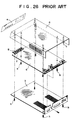
- the housing of the appliance is made of conductor material such as metal plate as shown in FIG 26.
- a logic package (d) is placed in an upper case (a) having a plurality of bosses (c) and a lower case (b) of a L shape and secured there, an indication panel (e) is attached to a front portion of the upper case (a), and a push button (g) is installed on an electric key (f) mounted on the logic package (d)
- the upper case (a) is as described above made of metal plate or sheet, so that a number of manufacturing steps are necessary and workability of the appliance assembling is low since the lower case (b) is secured to the upper case (a) through a number of bosses (c) and screws (h).
- the push button switch portion is structured as shown in the official gazette of Utility Model Hei 1-142125 by attaching the push button unit to the housing side and then placing a logic package having electric keys mounted thereon in the housing.
- the push button unit is attached to the housing side, and then the logic package provided with electric keys mounted thereon is contained in the housing in order to structure the push button switch portion, so that it is impossible to confirm or know whether the push button switch portion is completely structured or not unitl the electric appliance is assembled resulting in poor workability of assembly.
- the electric appliance of the present invention is defined in claim 5.
- the housing structure of an electric appliance of the present invention is defined in claim 14.
- the present invention to provide a housing structure of the electric appliance, which housing don't use screw to assemble making assembling and disassembling workability of the structure improved.
- It is the fourth purpose of the present invention is to provide a housing structure of improved assembling and disassembling workability, wherein a side edge portion of the logic package is inserted and pushed into grooves of the logic package holding portion, so that it is easy to assemble the logic package onto the upper case, L shape protrusions of the hook are hooked on the front logic package holding portion and engagement hole portion of the lower case side engagement portion in order to assemble the upper and the lower cases.
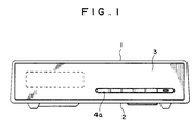
- FIG 1 is a front view of the electric appliance concerning an embodiment of the present invention.
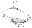
- FIG 2 is a perspective view of the embodiment above.
- FIG 3 is a plane view of the electric appliance.
- FIG 4 is a right side elevation of the electric appliance.
- FIG 5 is a rear view of the electric appliance.
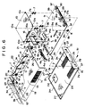
- FIG 6 is an exploded perspective view of the electric appliance.
- FIG 7 is a perspective view of the upper case of the appliance.
- FIG 8 is a perspective view of the lower case of the appliance.
- FIG 9 is a perspective view of the logic package.
- FIG 10 is a perspective view of the push button unit.
- FIG 11 is a detailed sectional view taken along line A-A in FIG 10.
- FIG 12 is a perspective depicting rear portion engagement condition of the electric appliance.
- FIG 13 is a section taken along line B-B in FIG 12.
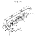
- FIG 14 is a perspective showing a front portion assembled of the electric appliance.
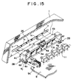
- FIG 15 is an exploded perspective view of the front portion.
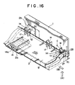
- FIG 16 is a perspective showing engagement condition of the upper case and lower case.
- FIG 17 is a section taken along line C-C shown in FIG 16.
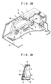
- FIG 18 is a sperspective showing a securing condition of liquid crystal indicator.
- FIG 19 is a section taken along line D-D shown in FIG 18.
- FIG 20 is a perspective showing installation of the logic package.
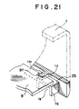
- FIG 21 is a section taken along line E-E in FIG 20.
- FIG 22 is an exploded perspective of the electric appliance of another embodiment according to the present invention.
- FIG 23 is an exploded perspective of the electric appliance of still another embodiment.
- FIG 24 is a perspective of the rear portion of the electric appliance.
- FIG 25 is a perspective of the insulator bushing.
- FIG 26 is an exploded perspective of the conventional electric appliance.
- An electric appliance is structured with a plastic-made upper case 1, a metal-made lower case, indication panel 3, push button unit 4, and logic packages 9 and 10.
- the upper case 1 has an upper face portion 1A, the left and the right side face portions 1B, 1C and a front face portion 1D, failing to have a rear face portion.
- the front face portion 1D is a slanted face inclined downward.
- the left side portion 1B has heat radiation holes 1a and the left and the right side face portions 1B and 1C have logic package holding portions 20, 21, and 22, respectively so formed at front, rear, and center positions of the inner face portions of the side face portions as to protrude from the upper case 1.
- the front and central logic package holding portions 20 and 22 have the same structure. They are structured or combined by combining both the upper and the lower U shape protrusions 1e and 1f back to back leaving a guide groove 1z between them, and leaving an insertion groove lg between the lower U shape protrusion 1f and inner face portions of the left and the right side face portions 1B and 1C.
- the rear side logic package holding portion 21 is assembled as shown in FIGS 7, 16, and 17 by combining the upper and the lower U shape protrusions 1e and 1f back to back and leaving the guide groove 1z between them and the insertion groove 1g between the lower U shape protrusion 1f and the inner face portions of the left and the right side face portions 1B and 1C, then protruding a rear portion of the lower U shape protrusion 1f rearward from the upper U shape protrusion 1e forming a ptotruded or stepped portion of an engagement portion 23 for the upper case side engagement portion, and forming an engagement protrusion 1m as shown in FIG 21 at the front portion of the guide groove 1z so as to engage with the notch 9f of the logic package 9.
- the inner face portions of the left and the right side face portions 1B and 1C have front and rear longitudinal ribs 1h and these longitudinal ribs 1h have lower ribs 1y leaving gaps 1i.
- a front face portion 1D of the upper case 1 has a liquid crystal indicator containing portion 24 securely containing liquid crystal indicators (LCD)5 and a push button unit installation portion 25 on which the push button unit 4 is mounted.
- LCD liquid crystal indicators
- the liquid crystal indicator container or containing portion 24 has a rectangular opening 1t, a stepped portion 1d formed around the circumference of the rectangular opening 1t, and protrusion 1u and 1c placed above and below the opening 1t sandwiching liquid crystal indicators 5.
- the push button unit installation portion 25 has oval openings 1s accommodating the push buttons 4a.
- the oval opening 1s has a plurality of protrusions 1v formed on the upper and the lower face portions at a regular interval and holes 1r formed above and below the oval openings 1s in order to install the push button unit 4.
- the engagement portion 26 On the central portion of rear interior of the upper face portion 1A of the upper case 1, there is an engagement portion 26 of the upper case with which an end portion 2k of the rear face portion 2B of the lower case 2 engages.
- the engagement portion 26 is formed integrally with the lower case 1 and has a slanted face 1x and a groove 1w.
- the lower case 2 is integrally made of conductor such as metal plate in order to shield static electricity and noise from entering the electric appliance.
- the lower case 2 has a bottom portion 2A and rear portion 2B.
- the bottom portion 2A has a recess 2d for preventing contacting with ROM 14 mounted on the logic package 9 and heat radiating hole 2n.
- ribs 2e on both the sides of the bottom face portion 2A and these ribs 2e engage with the gaps 1g and 1j of the upper case 1.
- the hook 27 formed on the front portion of the rib 2e is made of L shape protrusion 2b having a notch 2c.
- the rib 2e has a flat portion 2j at its rear end and the cut-off portion of the rear end of the rib 2e functions as stopper 2q.
- the bottom face portion 2A has a rib 2m at its front edge portion.
- the rear portion 2B of the lower case 2 has a U shape notch 2h, bis hole 2g, plural openings 2r, and a notch 2f facing the stopper 2q formed at the rear end of the rib 2e and functioning an engagement hole of the lower case 2.
- the indication panel 3 has an oval hole 3b accommodating the push button 4a of the push button unit 4 and a transparent portion 3a for the liquid crystal indicator 5. As a result, the indicator 5 can be seen from the outside.
- the push button unit 4 has a rectangular case main body 4A and protrusions 4b positioned at four corners of the front face portion of the case main body 4A so as to engage with the holes 1r of the upper case 1.
- One side of front face of the case main body 4A has accommodation portion 41 for accommodating the front end portion 12a of light emission diode (LED)12 and the accommodation portion 41 has a hole 4m.
- a plurality of push buttons 4a are arranged in left and right direction on the front side of the case main body 4A. These push buttons 4a are attached to the case main body 4A through resilient connection pieces 4C.
- a stopper 4k is fixed respectively to the lower side of the push button 4a.
- Rear face of the push button 4a has a raised portion or stand 4d contacting with a front end 11a of the electric key 11. Pillars 4e are placed in the case main body 4A so as to position at rear of the gaps between the push buttons 4a.
- Engagement portions 28 are formed on the left and the right ends of the lower portion of the case main body 4A. These engagement portions 28, respectively have grooves 4g for accommodating front ends of the logic package 9 and a cantilever engagement piece 4h. A front end portion of the engagement piece 4h has a protrusion 4j engageable with the hole 9c of the logic package 9 and the protrusion 4j has a slanted face 4n.
- the logic package 9 is structured by a print substrate.
- a connector 15 having part of a terminal 15a connected to an earth is mounted on the logic package 9.
- a bottom face of the print substrate has a connector 14a and ROM 14.
- a face portion of the print substrate has a hole 9a on which a spacer 8 is installed and a hole 9b on which a spacer 7 is installed.
- a front edge portion of the print substrate has a plurality of electric keys 11, light emission diode (LED)12 provided with an indicator 12a, a hole 9c engaging with the push button unit 4, a hole 9e on which a holder 6 is installed, and a connector 13 for connecting the liquid crystal indicator (LCD)5.
- LED light emission diode
- a rear edge portion of the print substrate has connectors 29, 30 constructing interfaces, a package holder 17 having a cable holder 18a mounted thereon to secure the power cable 18, and a power switch 19.
- the package holder 17 has a screw hole 17a formed therein.
- Front end portions at both sides of the print substrate has a chamferred portion 9d and the rear portion of the print substrate has a notched portion 9f.
- the logic package 10 is of a print substrate and upper side portion of the logic package 10 has a connector 16 provided a terminal 16 mounted on part of the connector 16 and connected with an earth.
- Four corners of the print substrate have four holes 10a and the spacer 7 has a protrusion 7a and a reaf spring 7b.
- the liquid crystal indicator (LCD)5 has a connection cable 5a.
- an indication panel 3 is sticked surely on a front outside of the upper case 1.
- the logic packages 9 and 10 are secured by inserting the protrusions 7a, on the upper end and the lower end of the spacer 7 which is sandwiched between these packages 9 and 10 in order to make a gap between them preventing electronic parts mounted thereon from interferring to each other, into holes 9b and 10a of each logic packages 9 and 10 with aid of functioning of the reaf spring 7b.
- insertion of the protrusions 7a of the spacer 7 sandwiched between the logic packages 9 and 10 into the holes 9b and 10a makes positioning or position determination of the connectors 15 and 16 of respective logic packages 9, 10 while fitting of these connectors easy resulting in improved assemblage workability.
- the protrusion 8a of the spacer 8 is inserted upward through the hole 9a of the logic package 9 and the logic package 9 is secured by function of the reaf spring 8b.
- connection cable 5a connected to the liquid crystal indicator (LCD) is secured to a connector 13 mounted on the logic package 9.
- Protrusions 6a of the holders 6 are inserted into the holes 9e of the logic package.
- the push button unit 4 is mounted on the front end of the logic package 9 and structures the push button switch together with the electric key 11. That is, the front end of the logic package 9 is inserted into the resilient engagement piece 4h of the push button unit 4 and the bottom face of the case main body 4A, and a protrusion 4j formed on front end of the engagement piece 4h engages with the hole 9c of the logic package 9, as a result the push button unit 4 is secured to the logic package 9 and front end 11a of the electric key 11 mounted on the logic package 9 contacts with the raised portion 4d of the push button 4 obtaining or completing the push button switch.
- the indicator 12a of the light emission diode (LED) mounted on the logic package 9 is accommodated in the hole 4m of the push button unit 4.
- the slanted face 4m of protrusion 4j of the push button unit 4 makes insertion of the logic package 9 easy and the groove 4g functions a role of stopper while insertion movement of the logic package 9. Additionally, the resilient connection piece 4c of the push button unit 4 makes operation of the push button 4c smooth.
- the liquid crystal indicator (LCD)5, holder 6, the logic package 10 fixed through the spacers 7, and the spacers 8 are mounted on the logic package 9, the left and the right side edge portions of the logic package 9 are inserted into the guide groove 1z of the rear side logic packages holding portions 21 placed at the left and the right side portions of the upper case 1, the logic package 9 moves forward from rear of the upper case 1, the left and the right side edge portions of the logic package 9 are sequentially inserted into the guide grooves 1z of the center and the front logic package holding portions 20, 21, 22, the protrusion 1m of the rear side logic package holding portion 22 engages with the notch 9f formed at the rear portion of the logic package 9 in order to fix the logic package 9 to the upper case 1.
- the liquid crystal indicator (LCD)5, holder 6, the logic package 10 fixed through the spacers 7, and the spacers 8 are mounted on the logic package 9, the left and the right side edge portions of the logic package 9 are inserted into the guide groove 1z of the rear side logic packages holding portions 21 placed at the left and the right
- the chamferred portion 9d formed on the front portion of the logic package 9 and roundness 1n of the entrace portion of the guide groove 1z of the logic package holding portions 20, 21, 22 make insertion workability of the logic package 9 improved.
- upper portion and both sides of the liquid crystal indicator (LCD)5 fit in the stepped portion 1d formed at the front portion of the upper case.
- the upper portion of the LCD5 engages with the protrusion 1u of the upper case 1 and the lower portion of the LCD5 is mounted on the protrusion 1c.
- the holder 6 having its lower portion mounted on the logic package 9 restricts rearward movement of the LCD5 and the resilient fixing portion 6b of the holder 6 absorbs shock of the LCD5.
- the push button 4a of the push button unit 4 and the accommodation portion 41 accommodating the LED 12 are accommodated in the oval hole 1s of the upper case 1, and the protrusion 4b of the push button unit 4 engages with the hole 1r of the upper case 1, as a result the push button unit 4 is secured to the upper case. It is noted that the protrusion 1r of the upper case 1 prevents the push buttons 4a of the push button unit 4 from mutually contacting with each other.
- the pillars 4e of the push button unit 4 prevents the interior of the electric appliance from being seen through a gap or space between the push buttons 4a while the front side of the appliance is seen. Also, as shown in FIGS 11 and 15, the engagement portions 4k of the push buttons 4a come contact with the lower edge of the oval hole 1s of the upper case 1 in order to prevent the front ends of the plural push buttons 4a from being uneven.
- the upper case 1 is turned over making its upper face 1A directed downward, then L shape protrusion 2b of the lower case 2 is inserted under the front logic package holding portion 20 of the upper case 1 and secured there, the lower case 2 turns toward the upper case 1 around a fulcrum of the front logic package holding portion 20 so as to overlap the lower case 2 upon the upper case 1, and the left and the right ribs 2e of the lower case 2 engage with the gaps 1g and 1j of the upper case 1.
- the lower case 2 is pushed frontward, and end portion 2k of the rear face 2B of the lower case 2 slides along the slanted face 1x of the engagement portion 26 near the rear and center portion of the upper case 1 in order to make the end portion 2k engaged with the groove 1w.
- the lower case 2 is pushed upwardly along an arrow A direction as shown by broken lines in FIGS 16 and 17, then slides in an arrow B direction to its position on the upper case 1. Consequently, an engagement portion 23 at a rear end of the rear and lower U shape protrusions 1f of the upper case 1 is inserted between the flat portion 2j and the notch 2f of the lower case 2.
- the logic package holding portion 20 and L shape protrusion 2b are engaged with each other at the front portion of the cases and the engagement portion 23 engages with the rear notch 2f.
- the upper case 1 and the lower case 2 are horizontally secured, an engagement at the rear center portion of the cases, or an engagement of the end portion 2k of the rear face portion 2B of the lower case 2 and the engagement portion 26 of the upper case 1 are carried out.
- the slanted face 1x of the upper case 1 makes insertion of the end portion 2k of the lower case 2 easy and workability of engagement of the groove 1w of the upper case 1 and the end portion 2k of the lower case 2 becomes easy since about the groove 1w of the upper case 1 deforms as shown by dotted lines.
- the lower case 2 moves upwardly in the direction A to its installation position on the upper case 1 and slides in the direction B, so that the engagement portion 23 of the rear end portion of the rear lower U shape protrusion 1f of the upper case 1 engages with between notch 2f and flat portion 2j of the lower case 2.
- the lower case 2 slides along the arrow C direction and the lower case 2 stops when the end portion 21 of the rib 2e of the lower case 2 contacts with an inside of the rib 1q of U shape protrusion 1f of the upper case 1.
- the lower case 2 and ROM 14 mounted on the connector 14a on the bottom face of the logic package 9 from contacting to each other while the lower case 2 is installed and disassembled.
- the spacer 8 mounted on the bottom face of the logic package 9 prevents the lower case 2 from contacting to the logic package 9 when the electric appliance is upwardly pushed.
- FIG 1 to FIG 5 show the electric appliance assembled.
- the bis 31 intends to electrically conduct the lower case 2 to the earth of the logic package 9 through the package holder 17 and the bis 31 is not so important to the assemblage of the housing of the electric appliance according to the present invention. Using this bis 31 makes the upper and the lower cases 1 and 2 and the logic package 9 strongly binded.
- ROM 14 is mounted on the connector 14a and on the bottom face of the logic package 9, it is easy to exchange ROM 14 only by disassembling the lower case 2.
- the purpose of the recess 2d of the lower case 2 is to lessen the height of the electric appliance of the present invention by placing the bottom face of the lower case 2 and a rubber seat 32.
- FIG 22 shows another embodiment of the electric appliance according to the present invention.
- a screw seat 33 is provided on the inner face portion of the upper face portion 1A of the upper case 1
- a screw hole 34 is formed on the lower case 2
- the upper and the lower cases 1 and 2 are assembled as mentioned above, and the bis 35 is threaded into the screw seat 33 through the screw hole 34 in order to make the fixing of the lower case 2 and upper case 1 sure.
- FIG 23 shows still another embodiment of the present invention.
- the rear edge portion of the print substrate of the logic package 9 has connectors 29, 30 structuring interfaces, package holder 17 having a power cable 18 secured by a cable holder 18a and mounted thereon, a power switch 19, and earth terminal 36.
- the rear edge portion of the print substrate has a power switch 19, earth terminal 36, connector 29, connector 30, respectively arranged in this order from the left side to the right side toward the front face of the print substrate.
- the package holder 17 is placed in front of the earth terminal 36.
- the earth terminal 36 has only the function of earth connection and screw hole 36a for the function.
- the power cable 18 has an insulator bushing 37 functioning to protect the power cable 18 from the notch 2h of the rear face portion 2B of the lower case 2.
- the insulator bush 37 has a central hole 37b through which the cable 18 passes and a circumferential groove 37a in which an edge portion of notch 2h is inserted.
- the rear portion of the logic package 9 has a connector 29 structuring interface and the power switch 19, and the package holder 17 having the power cable 18 mounted thereon is removed leaving a vacant space.
- Earth terminal 36 having only the earth connection function is mounted on the space
- rear face portion of the lower case 2 has a notch 2n
- the insulator bushing 37 through which the power cable 18 passes is removably fixed to the notch 2h, so that it is possible to mount more interfaces on the logic package 9 miniaturizing the electric appliance and simplifying the assemblage and disassemblage of the appliance.
- the assembling method of an electric appliance comprising an upper case having a plurality of logic package holding portions arranged on the inner side of the left and the right side face portions in front and rear direction at a regular interval and the upper case side engagement portion, a lower case having hooks formed at the left and the right front portions and the lower case side engagement portion, a push button unit, a logic package and grooves for inserting the logic package, is characterized by the steps of installing the push button unit on the logic package, inserting the logic package into the upper case using as a guide the grooves formed at the logic package holding portion and holding the package there, hooking the hook portions of the lower case on the most front logic package holding portion in order to revolve the lower case toward the upper case side and overlap the lower case upon, upper case, pushing-in the lower case in order to make the lower case side engagement portion engaged with the upper side engagement portion, thus no screw is used comparing to the conventional one resulting in simplicity of the assemblage of the electric appliance and improvement of the workability of assemblage.
- an electric appliance comprising an upper case, a lower case, a logic package and grooves for inserting the logic package
- the plastic upper case has a plurality of logic package holding portions arranged on the interior of the left and the right side face portions in the front and rear direction at a regular interval and the upper case side engagement portion
- the conductive lower case is provided with the lower case side engagement portions and hooks arranged on the left and the right front portions, said hooks being hooked on the most front logic package holding portion in order to turn lower case toward the upper case side and to overlap it on the upper case and to push the lower case resulting in an engagement of the lower case side engagement portion with the upper case side engagement portion
- the logic package is inserted in the upper case using a guide of the logic package holding portion and secured there
- a push button unit is removably installed on the logic package, so that it is possible to easily disassemble to upper case, lower case, and the logic package and to sort them according to the kind of material simplifying waste treatment of the electric appliance.
- a housing structure of the electric appliance comprising an upper case and a lower case is characterized in that the upper case is provided with a plurality of logic package holding portions arranged on the interior of the left and the right side face portions in the front and rear direction at a regular interval and the upper case side engagement portion, the lower case is provided with the lower case side engagement portions and hooks arranged on the left and the right front portions, said hooks being hooked on the most front logic package holding portion in order to turn the lower case toward the upper case side and to overlap lower case on the upper case and to push the lower case resulting in an arrangement of the lower case side engagement portion with the upper case side engagement portion, so that it is possible to carry out assemblage and disassembling operation of the housing of the electric appliance and improve assemblage and disassemblage workability.
- the logic package holding portion formed on the interior faces of the left and the right side portions has a horizontal groove through which the side edge portion of the logic package is inserted, the upper case side engagement portion at least protrudes rearward toward the under side portion of the rear logic package holding portion, the lower case side engagement portion is provided on a L shape or curved portion format at a rear face portion of the lower case, said upper case side engagement portion is an engagement hole adapted to engage with the engagement portion when the lower case is matched with upper case, and hooks are L shape protrusions having notches to be hooked on the front logic package holding portion, so that when the side edge portion of the logic package is forcibly inserted in the groove of the logic package holding portion, it is easy to assemble the logic package to the upper case, L shape protrusions of the hooks are hooked on the front logic package holding portion, and engagement hole of the lower case side engagement portion engages with the engagement portion of the upper case side engagement portion in order to carry out assemblage of the upper and the lower cases and
- the liquid crystal indicator fits into the stepped portion of the opening, the upper portion of the liquid crystal indicator engages with the upper protrusion, the lower portion of the liquid crystal indicator engages with the lower protrusion in order to prevent up and down direction and right and left direction movement of the indicator, a pressing member mounted on the logic package presses the rear face of the liquid crystal indicator in order to hold the indicator preventing its rearward movement.
- no screw is used simplifying a fixing of the liquid crystal indicator and improving its assemblage workability.
- the fixing structure of the liquid crystal indicator has a resilient holding member pressing the rear face of the liquid crystal indicator, so that no screws is used, the liquid crystal indicator can be easily held and shock applied to the liquid crystal indicator when the electric appliance is handled can be absorbed.
- the case has a push button switch installation portion provided with a push button switch portion
- the logic package having a plurality of electric keys arranged its front edge portion has engagement portions
- the push button unit has a plurality of push buttons arranged on the front face portion of the case main body in right and left direction, these push buttons are attached to the case main body through resilient push button connection pieces
- the case main body has engagement portions adapted to engage with the logic package engagement holes
- the engagment portion engage with the engagement holes of the logic package
- the push button unit is installed on the front edge portion of the logic package in order to contact the front ends of the electric keys to the back of the push button structuring the push button switch portion and pushing-in of the logic package makes the push button switch portion installed in the push button switch installation portion of the case.
- the push button switch portion is structured by engaging the engaging portion with the engagement holes of the logic package, installing the push button unit on the front edge portion of the logic package, making the front ends of the electric keys contacted with the back face of the push button, then pushing-in the logic package so as to install the push button switch portion the push button switch installation portion of the case.
- the electric appliance has a plastic upper case provided with a plurality of logic package holding portions arranged on the inner side of the left and the right side face portions in front and rear direction at a regular interval, as well as upper case side engagement portions, a conductive lower case having lower case side engagement portions and the left and the right front hooks, said hooks being adapted to hook on the most front logic package holding portion and the lower case being turned to upper case side and overlapped on the upper case and pushed into the upper case in order to make the lower case side engagement portion engaged with the upper case side engagement portion, the logic package adapted to insert and be held in the upper case using the logic package holding portion as a guide for insertion, and a connector and power switch structuring interfaces which are placed at rear of the logic package.
- the package holder securing and mounting power cable is removed leaving a space in which earth terminal having only earth connection function, rear face portion of the lower case has a notch, and an insulator bushing through which power cable passes is removably attached to the notch, as a result, no screw is used in the housing structure comparing to the conventional housing employing fastening screws resulting in easy assemblage of electric appliance and improved workability of assemblage, while it is possible to mount more interfaces on the logic package, to miniaturize the electric appliance, and simplify its assemblage and disassemblage.
Landscapes
- Engineering & Computer Science (AREA)
- Microelectronics & Electronic Packaging (AREA)
- Multimedia (AREA)
- Signal Processing (AREA)
- Casings For Electric Apparatus (AREA)
- Switch Cases, Indication, And Locking (AREA)
Claims (16)
- Verfahren zum Zusammenbauen eines elektrischen Gerätes mit einem oberen Gehäuse (1), das mit einer Vielzahl von Halteteilen (20, 21, 22) für Logikbaugruppen, die an den Innenseiten der linken und rechten Seitenflächenteile (1B, 1C) in Richtung nach vorne und nach hinten des oberen Gehäuses (1) in einem regelmäßigen Abstand vorgesehen sind, und mit Seiteneingriffseinrichtungen (26) des oberen Gehäuses versehen ist, mit einem unteren Gehäuse (2), das mit Haken (27), die an vorderen Teilen der rechten und der linken Seite des unteren Gehäuses ausgebildet sind, und einem Seiteneingriffsteil (2k) des unteren Gehäuses versehen ist, mit einer logischen Baugruppe (9) und Rillen (1z) zum Einsetzen der logischen Baugruppe (9), welches Verfahren die Schritte umfaßt:Einsetzen der logischen Baugruppe (9) in die Rillen (1z), die an den Halteteilen (20, 21, 22) für die logischen Baugruppen des oberen Gehäuses (1) ausgebildet sind,Einhaken der Haken (27) des unteren Gehäuses (2) am vordersten Halteteil (20) für die logischen Baugruppen derart, daß das untere Gehäuse (2) bezüglich des oberen Gehäuses (1) verschiebbar und drehbar angeordnet ist,Anordnen des unteren Gehäuses (2) derart, daß es das obere Gehäuse (1) überlappt, indem das untere Gehäuse (2) um die Haken (27) gedreht wird, undDrücken des unteren Gehäuses (2) nach vorne und gegen das obere Gehäuse (1), um den Seiteneingriffsteil (2k) des unteren Gehäuses mit dem Seiteneingriffsteil (26) des oberen Gehäuses in Eingriff zu bringen, so daß das obere Gehäuse (1) am unteren Gehäuse (2) fest angebracht ist.
- Verfahren zum Zusammenbauen eines elektrischen Gerätes nach Anspruch 1, dadurch gekennzeichnet, daß
das elektrische Gerät weiterhin eine Druckknopfbaueinheit (4) umfaßt und daß das Verfahren weiterhin den Schritt der Anbringung der Druckknopfbaueinheit (4) an der logischen Baugruppe (9) umfaßt. - Verfahren zum Zusammenbauen eines elektrischen Gerätes nach Anspruch 1 oder 2, dadurch gekennzeichnet, daß
das elektrische Gerät weiterhin eine Flüssigkristallanzeige (5) umfaßt und daß das Verfahren weiterhin den Schritt der Anbringung der Flüssigkristallanzeige (5) am oberen Gehäuse (1) umfaßt. - Verfahren zum Zusammenbauen eines elektrischen Gerätes nach Anspruch 1, 2 oder 3, dadurch gekennzeichnet, daß
das elektrische Gerät weiterhin eine Anschluß- und Netzschalterstrukturierungsschnittstelle (19, 36, 29, 30) und einen Baugruppenhalter (17) umfaßt und daß das Verfahren weiterhin den Schritt der Anbringung der Anschluß- und Netzschalterstrukturierungsschnittstelle (19, 36, 29, 30) und des Baugruppenhalters (17) an der logischen Baugruppe (9) umfaßt. - Elektrische Gerät mit einem oberen Gehäuse (1), einem unteren Gehäuse (2), einer logischen Baugruppe (9) und Rillen (1z) zum Einsetzen der logischen Baugruppe (9), wobeidas obere Gehäuse (1) mit einem Seiteneingriffsteil (26) des oberen Gehäuses und mit einer Vielzahl von Halteteilen (20, 21, 22) für logische Baugruppen versehen ist, die an der Innenseite der linken und rechten Flächenteile (1B, 1C) in Richtung nach vorne und nach hinten des oberen Gehäuses (1) in einem regelmäßigen Abstand vorgesehen und mit den Rillen (1z) versehen sind, unddas untere Gehäuse (2) einen Seiteneingriffsteil (2k) des unteren Gehäuses und linke und rechte Haken (27) aufweist, welche Haken (27) so ausgebildet sind, daß sie am vordersten Halteteil für die logischen Baugruppen eingehakt werden können, um das untere Gehäuse (2) so anzuordnen, daß es das obere Gehäuse (1) überlappt, so daß ein Drücken des unteren Gehäuses (2) nach vorne und gegen das obere Gehäuse (1) zu einer Ineingriffnahme des Seiteneingriffsteils (2k) des unteren Gehäuses mit dem Seiteneingriffsteil (26) des oberen Gehäuses führt, wobeidie Seitenkantenteile der logischen Baugruppe (9) in die Rillen (1z) eingesetzt werden können, um diese im oberen Gehäuse (1) zu halten.
- Elektrisches Gerät nach Anspruch 5, dadurch gekennzeichnet, daß
der Seiteneingriffsteil (26) des oberen Gehäuses sich an einem mittleren und rückseitigen Innenteil des oberen Gehäuses (1) befindet und der Seiteneingriffsteil (2k) des unteren Gehäuses ein Randteil (2k) einer rückseitigen Fläche (2B) des unteren Gehäuses (2) ist, so daß der Randteil (2k) mit dem Seiteneingriffsteil (26) des oberen Gehäuses in Eingriff kommt, wenn das untere Gehäuse (2) in das obere Gehäuse (1) gepaßt wird. - Elektrisches Gerät nach Anspruch 5 oder 6, dadurch gekennzeichnet, daß
die Haken (27) L-förmige Vorsprünge (2b) mit Nuten (2c) sind, die an den vordersten Halteteilen (20) für logische Baugruppen eingehakt werden können. - Elektrisches Gerät nach Anspruch 5, 6 oder 7, gekennzeichnet durch eine Druckknopfbaueinheit (4), die abnehmbar an der logischen Baugruppe (9) angebracht ist,wobei die Druckknopfbaugruppe (4) einen Hauptgehäusekörper (4A) aufweist, in dem eine Vielzahl von Druckknöpfen (4a) in Richtung nach links und nach rechts des Hauptgehäusekörpers (4A) angeordnet ist und der mit einem Eingriffsteil (28) versehen ist,das obere Gehäuse (1) weiterhin mit einem Anbringungsteil (25) für die Druckknopfeinheit an einem Vorderflächenteil (1D) des oberen Gehäuses (1) versehen ist, um diese Druckknöpfe (4a), die in der Druckknopfbaueinheit (4) angeordnet sind, anzubringen, unddie logische Baugruppe (9) weiterhin mit einer Vielzahl von elektrischen Tasten (11), die den jeweiligen Druckknöpfen (4a) entsprechen, und einem Eingriffslochteil (9c) versehen ist, der mit dem Eingriffsteil (28) der Druckknopfbaueinheit (4) in Eingriff kommen kann, um die Druckknopfbaueinheit (4) am vorderen Randbereich der logischen Baugruppe (9) anzubringen und die vorderen Enden (11a) dieser elektrischen Tasten (11) mit den Rückflächen (4d) dieser Druckknöpfe (4a) in Kontakt zu bringen.
- Elektrisches Gerät nach Anspruch 8, dadurch gekennzeichnet, daß
der Hauptgehäusekörper (4A) der Druckknopfbaueinheit (4) mehrere Stützen (4e) aufweist, um an der Rückseite der Zwischenräume zwischen diesen Druckknöpfen (4a) angeordnet zu werden. - Elektrisches Gerät nach Anspruch 8, dadurch gekennzeichnet, daßder Anbringungsteil (25) für die Druckknopfbaueinheit mehrere ovale Löcher (1s), die die Druckknöpfe (4a) aufnehmen, und mehrere Löcher (1r) aufweist, die über und unter den ovalen Löchern (1s) angeordnet sind,die Druckknopfbaueinheit (4) Vorsprünge (4b) aufweist, die mit Löchern (1r) des oberen Gehäuses (1) am Vorderflächenteil der Druckknopfeinheit (4) in Eingriff kommen, und der Eingriffsteil (28) eine Rille (4g), die den vorderen Endabschnitt der logischen Baugruppe (9) aufnimmt, und ein Armeingriffsteil (4h) aufweist, wobei das Armeingriffsteil (4a) einen Vorsprung (4j) aufweist, der mit einer abgeschrägten Fläche (4n) mit dem Eingriffslochteil (9c) der logischen Baugruppe (9) in Eingriff steht.
- Elektrisches Gerät nach Anspruch 8, dadurch gekennzeichnet, daßder Anbringungsteil (25) für die Druckknopfbaugruppe mit mehreren ovalen Löchern (1s), die die Druckknöpfe (4a) aufnehmen, mit einer Vielzahl von Vorsprüngen (1v), die an den oberen und den unteren Flächenteilen der ovalen Löcher (1s) in regelmäßigen Abständen ausgebildet sind, und mit Löchern (1r) strukturiert ist, die über und unter den ovalen Löchern (1s) angeordnet sind, unddie Druckknopfbaugruppe (4) so ausgebildet ist, daß die Druckknöpfe (4a) an den Vorderflächenteilen des Hauptgehäusekörpers (4) in Richtung nach rechts und nach links angeordnet sind, die Druckknöpfe (4a) am Hauptgehäuseteil (4A) über elastische Druckknopfverbindungsteile (4c) angebracht sind, Anschläge (4k) an den Druckknöpfen (4a) ausgebildet sind, die mit den Randteilen der ovalen Löcher (1s) in Kontakt kommen können, wenn die Druckknopfbaueinheit (4) am oberen Gehäuse (1) angebracht ist, und ein Eingriffsteil (28) am Hauptgehäuseteil (4A) so ausgebildet ist, daß er mit dem Eingriffslochteil (9c) der logischen Baugruppe (9) in Kontakt steht.
- Elektrisches Gerät nach Anspruch 5, 6 oder 7, welches weiterhin eine Flüssigkristallanzeige (5) umfaßt, die abnehmbar am oberen Gehäuse (1) angebracht ist, dadurch gekennzeichnet, daßdas obere Gehäuse (1) weiterhin mit einem Aufnahmeteil (24) für die Flüssigkristallanzeige versehen ist, der die Flüssigkristallanzeige (5) aufnimmt, wobei der Aufnahmeteil (24) für die Flüssigkristallanzeige einen Öffnungsteil (1t), einen abgestuften Teil (1d), der um den Umfang des Öffnungsteils (1t) herum ausgebildet ist und in den der Rahmen der Flüssigkristallanzeige (5) paßt, einen oberen Vorsprung (1u), der über dem Öffnungsteil (1t) angeordnet ist und mit dem oberen Teil der Flüssigkristallanzeige (5) in Eingriff steht, und einen unteren Vorsprung (1c) aufweist, der unter der oberen Öffnung (1t) angeordnet ist und mit dem unteren Teil der Flüssigkristallanzeige (5) in Eingriff steht, unddie logische Baugruppe (9) weiterhin mit einem Halteelement versehen ist, durch das der Rückflächenteil der Flüssigkristallanzeige (5) unter Druck gesetzt und gehalten ist.
- Elektrisches Gerät nach Anspruch 5, 6 oder 7, dadurch gekennzeichnet, daßdie logische Baugruppe (9) mit einer Anschluß- und Netzschalterstrukturierungsschnittstelle (19, 29, 30, 36) versehen ist,ein Baugruppenhalter (27) mit einem Versorgungskabel (18), das daran angebracht und befestigt ist, abgenommen werden kann, so daß ein Raum bleibt, in dem ein Masseanschluß mit nur Masseanschlußfunktion angeordnet ist,der Rückflächenteil des unteren Gehäuses (2) eine Nut (2a) aufweist undeine Isolatorbuchse (37), durch die das Versorgungskabel (18) führt, abnehmbar an der Nut (2a) angebracht ist.
- Gehäuseaufbau eines elektrischen Gerätes mit einem oberen Gehäuse (1) und einem unteren Gehäuse (2), wobeidas obere Gehäuse (1) mit einem Seiteneingriffsteil (26) des oberen Gehäuses und mehreren Halteteilen (20, 21, 22) für logische Baugruppen versehen ist, die an der Innenseite der linken und rechten Flächenteile (1B, 1C) in Richtung nach vorne und nach hinten des oberen Gehäuses (1) in regelmäßigen Abständen angebracht sind, unddas untere Gehäuse (2) einen Seiteneingriffsteil (2k) des unteren Gehäuses und rechte und linke Haken (27) aufweist, welche Haken (27) an dem vordersten Halteteil (20) für die logischen Baugruppen einhaken können, um das untere Gehäuse (2) so anzuordnen, daß es das obere Gehäuse (1) derart überlappt, daß ein Drücken des unteren Gehäuses (2) nach vorne und gegen das obere Gehäuse (1) zu einer Ineingriffnahme des Seiteneingriffsteils (2k) des unteren Gehäuses mit dem Seiteneingriffsteil (26) des oberen Gehäuses führt.
- Gehäusekonstruktion des elektrischen Gerätes nach Anspruch 14, dadurch gekennzeichnet, daß
der Seiteneingriffsteil (26) des oberen Gehäuses am mittleren und hinteren Innenteil des oberen Gehäuses (1) angeordnet ist und der Seiteneingriffsteil (2k) des unteren Gehäuses ein Randteil (2k) einer Rückfläche (2B) des unteren Gehäuses (2) ist, derart, daß der Randteil (2k) mit dem Seiteneingriffsteil (26) des oberen Gehäuses in Eingriff kommt, wenn das untere Gehäuse (2) an das obere Gehäuse (1) gepaßt wird. - Gehäusekonstruktion des elektrischen Gerätes nach Anspruch 14 oder 15, dadurch gekennzeichnet, daß
die Haken (27) L-förmige Vorsprünge (2b) sind, die Nuten (2c) aufweisen, die mit den vordersten Halteteilen (20) für die logischen Baugruppen verhakt werden können.
Applications Claiming Priority (8)
| Application Number | Priority Date | Filing Date | Title |
|---|---|---|---|
| JP28109592A JP3198665B2 (ja) | 1992-09-28 | 1992-09-28 | 電気機器装置の押ボタンスイッチ構造 |
| JP4281094A JP2890372B2 (ja) | 1992-09-28 | 1992-09-28 | 電気機器装置の組立方法と電気機器装置とその筐体構造 |
| JP28109692A JP2941133B2 (ja) | 1992-09-28 | 1992-09-28 | 電気機器装置における液晶表示器の固定構造 |
| JP281096/92 | 1992-09-28 | ||
| JP281095/92 | 1992-09-28 | ||
| JP281094/92 | 1992-09-28 | ||
| JP138922/93 | 1993-05-18 | ||
| JP13892293A JP2873264B2 (ja) | 1993-05-18 | 1993-05-18 | 電気機器装置 |
Publications (2)
| Publication Number | Publication Date |
|---|---|
| EP0590609A1 EP0590609A1 (de) | 1994-04-06 |
| EP0590609B1 true EP0590609B1 (de) | 1998-05-27 |
Family
ID=27472182
Family Applications (1)
| Application Number | Title | Priority Date | Filing Date |
|---|---|---|---|
| EP93115648A Expired - Lifetime EP0590609B1 (de) | 1992-09-28 | 1993-09-28 | Elektrisches Gerät, sein Herstellungsverfahren und seine Gehäusestruktur |
Country Status (3)
| Country | Link |
|---|---|
| US (5) | US5461543A (de) |
| EP (1) | EP0590609B1 (de) |
| DE (1) | DE69318791T2 (de) |
Families Citing this family (15)
| Publication number | Priority date | Publication date | Assignee | Title |
|---|---|---|---|---|
| EP0689341B1 (de) * | 1994-05-24 | 2000-07-26 | Pfu Limited | Bildabtaster mit Systemerweiterungsfunktion |
| US6181404B1 (en) * | 1998-02-27 | 2001-01-30 | 3Com Corporation | Apparatus and method for mounting a liquid crystal display (LCD) assembly onto a printed circuit board |
| USD413572S (en) | 1998-03-09 | 1999-09-07 | Schneider Automation Inc. | Terminal block |
| US6080946A (en) * | 1999-08-23 | 2000-06-27 | D-Link Corporation | Dip switch with enhanced anti-EMI performance |
| US6445429B1 (en) * | 1999-11-02 | 2002-09-03 | Telefonaktiebolaget L M Ericsson (Publ) | Method for assembling a liquid crystal display panel in a mobile telephone |
| US7418838B2 (en) * | 2002-04-17 | 2008-09-02 | Lg Electronics Inc. | Washer |
| KR100680194B1 (ko) * | 2002-11-29 | 2007-02-08 | 엘지전자 주식회사 | 세탁기의 컨트롤 패널 마운팅 구조 |
| DE10336089B4 (de) * | 2003-08-06 | 2008-06-05 | Iq Automation Gmbh | Montageeinheit für ein Display |
| DE102005009798A1 (de) * | 2005-03-03 | 2006-09-07 | Siemens Ag | Elektrisches Gerät |
| CN2874751Y (zh) * | 2006-01-13 | 2007-02-28 | 鸿富锦精密工业(深圳)有限公司 | 面板按键结构 |
| US7706145B2 (en) * | 2006-04-10 | 2010-04-27 | Super Micro Computer, Inc. | Assembly device for a computer case and outer cover |
| CN102483202B (zh) | 2010-05-06 | 2013-03-27 | 松下电器产业株式会社 | 灯及照明装置 |
| EP2568786A1 (de) * | 2010-06-10 | 2013-03-13 | Thomson Licensing | Vorrichtung zum Befestigen einer Leiterplatte |
| US8611077B2 (en) * | 2010-08-27 | 2013-12-17 | Apple Inc. | Electronic devices with component mounting structures |
| CN104122691B (zh) * | 2013-04-25 | 2017-03-01 | 冠捷投资有限公司 | 无螺丝的显示装置 |
Family Cites Families (17)
| Publication number | Priority date | Publication date | Assignee | Title |
|---|---|---|---|---|
| FR2198239B1 (de) * | 1972-09-07 | 1975-03-07 | Telic | |
| JPS5818299Y2 (ja) * | 1978-04-28 | 1983-04-13 | 富士通株式会社 | プリント基板ユニット内蔵型電子機器 |
| US4355483A (en) * | 1981-01-05 | 1982-10-26 | The Quaker Oats Company | Switch mechanism |
| US4422728A (en) * | 1981-01-30 | 1983-12-27 | Sangamo Weston, Inc. | Liquid crystal mounting and connection scheme |
| US4672510A (en) * | 1984-10-19 | 1987-06-09 | Burr-Brown Corporation | Package for an expandable remote interface unit |
| JPH0337264Y2 (de) * | 1985-01-17 | 1991-08-07 | ||
| DE3685598T2 (de) * | 1985-03-20 | 1993-01-21 | Casio Computer Co Ltd | Kompaktes batteriegespeistes elektronisches geraet. |
| JPS61168685U (de) * | 1985-04-08 | 1986-10-20 | ||
| JPH056697Y2 (de) * | 1987-10-08 | 1993-02-19 | ||
| JPH01142125U (de) * | 1988-03-25 | 1989-09-28 | ||
| DE8903217U1 (de) * | 1989-03-15 | 1990-07-12 | Philips Patentverwaltung Gmbh, 2000 Hamburg | Leiterplattengehäuse |
| JP2875327B2 (ja) * | 1990-03-02 | 1999-03-31 | 株式会社日立製作所 | 液晶表示装置 |
| US5157723A (en) * | 1991-02-21 | 1992-10-20 | Northern Telecom Limited | Mounts for articles |
| US5146390A (en) * | 1991-03-08 | 1992-09-08 | John Fluke Mfg. Co., Inc. | Lcd support bracket |
| US5172805A (en) * | 1991-05-23 | 1992-12-22 | Northern Telecom Limited | Pushbutton and carrying member combination for operating an electronic switching device |
| US5144533A (en) * | 1991-06-27 | 1992-09-01 | Motorola, Inc. | Self-locking housing assembly |
| US5455743A (en) * | 1993-02-19 | 1995-10-03 | Sony Corporation | Switch panel for electronic device |
-
1993
- 1993-09-28 EP EP93115648A patent/EP0590609B1/de not_active Expired - Lifetime
- 1993-09-28 DE DE69318791T patent/DE69318791T2/de not_active Expired - Fee Related
- 1993-09-28 US US08/127,568 patent/US5461543A/en not_active Expired - Fee Related
-
1995
- 1995-06-07 US US08/477,615 patent/US5594625A/en not_active Expired - Fee Related
- 1995-06-07 US US08/479,640 patent/US5602722A/en not_active Expired - Fee Related
-
1996
- 1996-08-28 US US08/697,555 patent/US5838402A/en not_active Expired - Fee Related
-
1997
- 1997-12-10 US US08/988,473 patent/US5905551A/en not_active Expired - Fee Related
Also Published As
| Publication number | Publication date |
|---|---|
| US5461543A (en) | 1995-10-24 |
| DE69318791T2 (de) | 1999-02-18 |
| EP0590609A1 (de) | 1994-04-06 |
| US5602722A (en) | 1997-02-11 |
| DE69318791D1 (de) | 1998-07-02 |
| US5838402A (en) | 1998-11-17 |
| US5594625A (en) | 1997-01-14 |
| US5905551A (en) | 1999-05-18 |
Similar Documents
| Publication | Publication Date | Title |
|---|---|---|
| US5461543A (en) | Electric appliance, its assembling method, and its housing structure | |
| EP1372021B1 (de) | Bildanzeigegerät | |
| JP3320259B2 (ja) | ケースのシール構造 | |
| EP2026423B1 (de) | Struktur aus abgeschirmten Steckverbindern | |
| US20040247311A1 (en) | Mounting structure for compact camera module | |
| US20060177960A1 (en) | Control module assembly | |
| US6275390B1 (en) | Shield for electronic components on a circuit board | |
| JPH11162423A (ja) | パック電池 | |
| US5581446A (en) | Housing structure of electric appliance and disassembling method thereof | |
| JP2890372B2 (ja) | 電気機器装置の組立方法と電気機器装置とその筐体構造 | |
| JP3131141B2 (ja) | 極板保持構造 | |
| JP2873264B2 (ja) | 電気機器装置 | |
| JP3198665B2 (ja) | 電気機器装置の押ボタンスイッチ構造 | |
| JP2941133B2 (ja) | 電気機器装置における液晶表示器の固定構造 | |
| JPH07183684A (ja) | 電気機器のシールド板構造 | |
| CN214189916U (zh) | 一种码表、装设有该码表的电动自行车及滑板车 | |
| JPS6334220Y2 (de) | ||
| CN219247016U (zh) | 一种网络面板 | |
| CN214216026U (zh) | 可拆卸的码表、电动自行车及滑板车 | |
| CN222483676U (zh) | 天线装置 | |
| CN214296274U (zh) | 码表的壳体结构、电动自行车及滑板车 | |
| CN211959941U (zh) | Pcba屏蔽罩与外壳的散热结构 | |
| CN210404799U (zh) | 一种车载充电器 | |
| JPH11111249A (ja) | 電池パック用ケース | |
| JP3681197B2 (ja) | 電気機器装置の筐体構造 |
Legal Events
| Date | Code | Title | Description |
|---|---|---|---|
| PUAI | Public reference made under article 153(3) epc to a published international application that has entered the european phase |
Free format text: ORIGINAL CODE: 0009012 |
|
| AK | Designated contracting states |
Kind code of ref document: A1 Designated state(s): DE FR GB |
|
| 17P | Request for examination filed |
Effective date: 19940511 |
|
| 17Q | First examination report despatched |
Effective date: 19950801 |
|
| GRAG | Despatch of communication of intention to grant |
Free format text: ORIGINAL CODE: EPIDOS AGRA |
|
| GRAG | Despatch of communication of intention to grant |
Free format text: ORIGINAL CODE: EPIDOS AGRA |
|
| GRAH | Despatch of communication of intention to grant a patent |
Free format text: ORIGINAL CODE: EPIDOS IGRA |
|
| GRAH | Despatch of communication of intention to grant a patent |
Free format text: ORIGINAL CODE: EPIDOS IGRA |
|
| GRAH | Despatch of communication of intention to grant a patent |
Free format text: ORIGINAL CODE: EPIDOS IGRA |
|
| GRAA | (expected) grant |
Free format text: ORIGINAL CODE: 0009210 |
|
| AK | Designated contracting states |
Kind code of ref document: B1 Designated state(s): DE FR GB |
|
| REF | Corresponds to: |
Ref document number: 69318791 Country of ref document: DE Date of ref document: 19980702 |
|
| ET | Fr: translation filed | ||
| PLBE | No opposition filed within time limit |
Free format text: ORIGINAL CODE: 0009261 |
|
| STAA | Information on the status of an ep patent application or granted ep patent |
Free format text: STATUS: NO OPPOSITION FILED WITHIN TIME LIMIT |
|
| 26N | No opposition filed | ||
| REG | Reference to a national code |
Ref country code: GB Ref legal event code: IF02 |
|
| PGFP | Annual fee paid to national office [announced via postgrant information from national office to epo] |
Ref country code: GB Payment date: 20020823 Year of fee payment: 10 |
|
| PGFP | Annual fee paid to national office [announced via postgrant information from national office to epo] |
Ref country code: FR Payment date: 20020927 Year of fee payment: 10 |
|
| PGFP | Annual fee paid to national office [announced via postgrant information from national office to epo] |
Ref country code: DE Payment date: 20020930 Year of fee payment: 10 |
|
| PG25 | Lapsed in a contracting state [announced via postgrant information from national office to epo] |
Ref country code: GB Free format text: LAPSE BECAUSE OF NON-PAYMENT OF DUE FEES Effective date: 20030928 |
|
| PG25 | Lapsed in a contracting state [announced via postgrant information from national office to epo] |
Ref country code: DE Free format text: LAPSE BECAUSE OF NON-PAYMENT OF DUE FEES Effective date: 20040401 |
|
| GBPC | Gb: european patent ceased through non-payment of renewal fee |
Effective date: 20030928 |
|
| PG25 | Lapsed in a contracting state [announced via postgrant information from national office to epo] |
Ref country code: FR Free format text: LAPSE BECAUSE OF NON-PAYMENT OF DUE FEES Effective date: 20040528 |
|
| REG | Reference to a national code |
Ref country code: FR Ref legal event code: ST |