EP0590624A1 - Dispositif de positionnement d'une scie verticale à panneaux - Google Patents
Dispositif de positionnement d'une scie verticale à panneaux Download PDFInfo
- Publication number
- EP0590624A1 EP0590624A1 EP93115677A EP93115677A EP0590624A1 EP 0590624 A1 EP0590624 A1 EP 0590624A1 EP 93115677 A EP93115677 A EP 93115677A EP 93115677 A EP93115677 A EP 93115677A EP 0590624 A1 EP0590624 A1 EP 0590624A1
- Authority
- EP
- European Patent Office
- Prior art keywords
- support
- adjusting device
- angle adjusting
- angle
- strut
- Prior art date
- Legal status (The legal status is an assumption and is not a legal conclusion. Google has not performed a legal analysis and makes no representation as to the accuracy of the status listed.)
- Granted
Links
Images


Classifications
-
- B—PERFORMING OPERATIONS; TRANSPORTING
- B23—MACHINE TOOLS; METAL-WORKING NOT OTHERWISE PROVIDED FOR
- B23Q—DETAILS, COMPONENTS, OR ACCESSORIES FOR MACHINE TOOLS, e.g. ARRANGEMENTS FOR COPYING OR CONTROLLING; MACHINE TOOLS IN GENERAL CHARACTERISED BY THE CONSTRUCTION OF PARTICULAR DETAILS OR COMPONENTS; COMBINATIONS OR ASSOCIATIONS OF METAL-WORKING MACHINES, NOT DIRECTED TO A PARTICULAR RESULT
- B23Q1/00—Members which are comprised in the general build-up of a form of machine, particularly relatively large fixed members
- B23Q1/25—Movable or adjustable work or tool supports
- B23Q1/44—Movable or adjustable work or tool supports using particular mechanisms
- B23Q1/50—Movable or adjustable work or tool supports using particular mechanisms with rotating pairs only, the rotating pairs being the first two elements of the mechanism
- B23Q1/52—Movable or adjustable work or tool supports using particular mechanisms with rotating pairs only, the rotating pairs being the first two elements of the mechanism a single rotating pair
- B23Q1/525—Movable or adjustable work or tool supports using particular mechanisms with rotating pairs only, the rotating pairs being the first two elements of the mechanism a single rotating pair which is parallel to the working surface
-
- B—PERFORMING OPERATIONS; TRANSPORTING
- B27—WORKING OR PRESERVING WOOD OR SIMILAR MATERIAL; NAILING OR STAPLING MACHINES IN GENERAL
- B27B—SAWS FOR WOOD OR SIMILAR MATERIAL; COMPONENTS OR ACCESSORIES THEREFOR
- B27B27/00—Guide fences or stops for timber in saw mills or sawing machines; Measuring equipment thereon
- B27B27/06—Guide fences or stops for timber in saw mills or sawing machines; Measuring equipment thereon arranged angularly with respect to the plane of the saw blade, e.g. for mitring
-
- B—PERFORMING OPERATIONS; TRANSPORTING
- B27—WORKING OR PRESERVING WOOD OR SIMILAR MATERIAL; NAILING OR STAPLING MACHINES IN GENERAL
- B27B—SAWS FOR WOOD OR SIMILAR MATERIAL; COMPONENTS OR ACCESSORIES THEREFOR
- B27B27/00—Guide fences or stops for timber in saw mills or sawing machines; Measuring equipment thereon
- B27B27/10—Devices for moving or adjusting the guide fences or stops
Definitions
- the invention relates to an angle adjustment device for a panel saw for the oblique arrangement of the sawing material.
- the material to be sawn must be stored at an angle so that the horizontal or vertical sawing path takes the desired oblique-angled direction in the material to be sawn.
- essentially wedge-shaped devices are used, which are inserted between the bearing surface of the saw and the material to be sawn and on which the saw then rests in an inclined position.
- Known devices of this type generally consist of two beams which are connected at one end via a hinge and can be pivoted relative to one another.
- the resulting V-shaped arrangement is placed with one of its legs on the support surface of the panel saw machine.
- the second leg thus forms an oblique surface for receiving the sawdust.
- a cross strut normally has to be attached between the two beams due to the large torques that occur.
- Such devices have several disadvantages. Since they can only be swung open on one side can often disrupt the workflow, for example. In particular, it may be necessary to adapt the loading direction and the cutting sequence to the geometry of the device.
- the bracing which is necessary to fix the angle, is very complex.
- the struts should not protrude beyond the beams if possible. These conditions can hardly be met at the same time, especially with small opening angles of the beams. Therefore, the existing solutions are very complex, difficult to use and expensive.
- the opening angle between the two bars should also be as easy to measure as possible. In the present solutions, this is only possible cost-effectively via relatively imprecise or otherwise via correspondingly expensive angle sensors on the hinge or via an indirect, non-linear measurement of the strut position and length.
- the essentially symmetrical structure reduces the applied torsional forces and also offers more space for a joint arrangement.
- the device can thus be made more stable, simple and user-friendly with better precision.
- Another advantage of the device according to the invention is that it can be used in all existing, in particular vertical panel saws without significant modification.
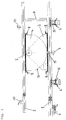
- FIG. 1 shows a first view of the device according to the invention in a horizontal position.
- the two supports which are preferably formed by aluminum profile rails 1 and 2 and are connected in a rocker-like manner by means of two joint parts 3 (bracket) and 4 (rocker) in an axis of rotation 5, are easily visible.
- the first, lower rail 1 forms a first, lower support and rests on the sawing machine, of which only the support rollers 6 for the sawing material are shown schematically.
- the second, pivotable upper rail 2 can be tilted to the first rail around the joint 5.
- the upper edge of this second rail defines an upper, second support on which the sawdust rests when the device is in operation.
- an adjustable and displaceable strut-like locking device 7 is provided.
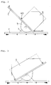
- FIGS. 2-5 show some schematic operating positions of the device with the sawing material 9 attached. It can be seen that the articulated parts 3 and 4 can be moved relative to both rails 1 and 2. This makes it possible to use very long rails without overlapping them at large seesaw angles. This means that angles up to +/- 45 ° can be easily adjusted.
- the rails are fastened to the respective joint parts 3 and 4 with quick-release fasteners 8 or screws for simple displacement. So that this shift can take place continuously, the rails are preferably each made of an aluminum profile with a continuous longitudinal groove in which the closures 8 engage.
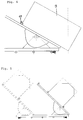
- Clamping elements 10 are provided for fixing the material to be sawn on the upper rail 2. These are, for example, metal blocks that are fastened in the rail 2 with screws or quick-release fasteners. If additional fastening of the sawdust is necessary, e.g. also a clamping element can be used, as shown in Figure 6. This element is also locked in the rail with a suitable lock (see e.g. Figure 8). By means of an eccentric 12, however, a plate 13 can additionally be pressed against the sawing material with the actuation of the lever, and this can thus be locked.
- a clamping element 11 can be used which, for example by means of two clamp-like jaws, laterally surrounds and holds the material to be sawn. This makes it possible to arrange the material to be sawn 9 in such a way that it projects beyond the lower end of the upper rail 2. This makes it possible to make a cut in the area of the corresponding lower corner of the sawing material, as is indicated schematically by a dash-dotted line.
- the opening angle of the device can be locked in the area of the joint parts 3 and 4, as will be described below. But you can also use a strut-like locking 7 between the rails, as shown schematically in Figure 1 and in Figure 7 in detail.
- this detent is formed from two toothed racks 14 and 15, the first toothed rack 14 being fastened to the lower rail 1 and the second toothed rack 15 to the upper rail 2.
- fastening arrangements 16, 17 are used for fastening to the rails, which are articulated with the respective rack 14 and. 15 are connected.
- one or two sleeves 18, 19 with two openings 20, 21 are used, through which the racks are guided.
- One (20) of the openings is elongated and allows the corresponding rack to move transversely to the direction of the bar.
- spring members 22, 23, one of which is mounted in each rack the two racks are pushed away from each other so that their teeth come apart. So that the rods can be freely moved against each other.
- Clamping screws (not shown) can be used in the sleeves 18, 19 at positions 24 and 25 to lock the rods. By inserting these clamping screws, the two rods are pressed against each other and interlocked.
- the two racks can be loosened and shifted from each other, whereby the total length of the locking device 7 can be regulated.
- the angle of the locking device relative to the rails 1 and 2 can also be adjusted by at least one of the locking arrangements 16, 17 is released and moved along the rails.
- a fine drive 26 is also provided, with which the lower part of the rod 14 can be moved.
- the setting angle can thus be regulated in the range of +/- 1 ° with a resolution of 0.01 °.
- the setting angle is advantageously measured in the area of the two joint parts 3 and 4.
- FIG. 8 shows a possible embodiment of the joint parts 3 and 4, on which the most important elements of the angle measurement can be seen.
- a scale 27 can be provided in one of the joint parts 4, which is attached to the other joint part 3, e.g. in an opening 28 is read.
- the accuracy of this angle measurement is not particularly high and the reading is tedious.
- the angle measurement is traced back to a length measurement.
- the movement of the outer edge 30 of the upper joint part 4 is monitored by means of a measuring device 29 on the lower joint part 3.
- the outer edge 30 follows an arc with a center in the axis of rotation 5 at least in a region of the joint part 4.
- the length measurement on this circular arc can be done in various ways, such as optically or electromechanically.
- the measurement takes place in a contactless magnetic way.
- Such measuring devices are known to the person skilled in the art from length measurement and have the advantage that they are insensitive to contamination and mechanical influences.
- a magnetic tape is attached to the outer edge 30, which has, for example, periodically alternating polarized domains.
- the measuring sensor 29 detects this information and gives it to an evaluation circuit further, which calculates and displays the corresponding setting angle.
- the corresponding evaluation circuit and the display 33 can e.g. be integrated in the lower joint part 3.
- the supply line is e.g. over a deflection roller, which is slidably mounted in the lower rail.
- An elastic band is attached to the pulley, which ensures that the supply line always remains taut.
- the accuracy of the angle measurement is essentially given by the radius of the outer edge 30 and the length resolution of the measuring device.
- an angular resolution better than 0.01 ° can be achieved.
- FIG. 8 further shows that adjustment bores 31 can also be provided in the joint plate 4. These can be used with a pin protruding through a corresponding hole in the lower joint plate 3 for fixing the upper joint plate 4 at discrete angles. Predetermined angles can thus be set quickly. A calibration position for the angle measuring device can also be adjustable in this way.
- Clamps 32 are used which surround the support rollers 6 of the saw (see Figure 1).
- the two rails 1 and 2 are displaceable with respect to the axis of rotation. So it is conceivable to firmly connect the lower rail 1 to the lower joint part 3.
- the rail 1 can also be chosen shorter or even omitted, so that it does not touch the top rail 2. In this case, it is particularly important that the device is well connected to the bench saw.
- the axis of rotation can also be arranged higher or lower.
- the strut-like locking device 7 can be attached to the two rails 1 and 2.
- a space is left between the joint parts 3 and 4, in which a worm gear is arranged.
- This consists of a ring gear 34 which is formed on the upper joint part 4; and a worm 35.
- the worm can be turned by means of a rotary handle 36 and is mounted in a block 37 on the lower joint part.
- your bearing is 38 designed so that it can be pushed away from the ring gear 34, whereby the upper joint part 4 is freely rotatable.
- a pressure spring 39 and a locking screw 40 are provided in the bearing 38.
- Such a lock allows a linear control of the setting angle with high precision.
- the device according to the invention in all cases offers a professional tool for working with vertical panel saws.
Landscapes
- Life Sciences & Earth Sciences (AREA)
- Engineering & Computer Science (AREA)
- Mechanical Engineering (AREA)
- Wood Science & Technology (AREA)
- Forests & Forestry (AREA)
- Sawing (AREA)
Applications Claiming Priority (2)
| Application Number | Priority Date | Filing Date | Title |
|---|---|---|---|
| CH3049/92 | 1992-09-30 | ||
| CH304992A CH686418A5 (de) | 1992-09-30 | 1992-09-30 | Winkeleinstellvorrichtung fuer eine Plattensoge. |
Publications (2)
| Publication Number | Publication Date |
|---|---|
| EP0590624A1 true EP0590624A1 (fr) | 1994-04-06 |
| EP0590624B1 EP0590624B1 (fr) | 1996-07-17 |
Family
ID=4247468
Family Applications (1)
| Application Number | Title | Priority Date | Filing Date |
|---|---|---|---|
| EP93115677A Revoked EP0590624B1 (fr) | 1992-09-30 | 1993-09-29 | Dispositif de positionnement d'une scie verticale à panneaux |
Country Status (4)
| Country | Link |
|---|---|
| EP (1) | EP0590624B1 (fr) |
| AT (1) | ATE140418T1 (fr) |
| CH (1) | CH686418A5 (fr) |
| DE (1) | DE59303246D1 (fr) |
Citations (7)
| Publication number | Priority date | Publication date | Assignee | Title |
|---|---|---|---|---|
| US2871768A (en) * | 1955-07-05 | 1959-02-03 | Jr Charles Henry Froberg | Adjustable angle plates |
| DE2365373A1 (de) * | 1973-11-23 | 1975-05-28 | Franz Arnold | Winkeleinstellvorrichtung, insbesondere fuer maschiennschraubstaecke |
| US4249446A (en) * | 1979-03-15 | 1981-02-10 | Tallerico Peter Jr | Coping tracing machine |
| US4911048A (en) * | 1988-05-19 | 1990-03-27 | Osborne Alonzo G | Sawmill gauge |
| DE3917146A1 (de) * | 1989-05-26 | 1990-11-29 | Hirsch Wilhelm | Anschlagvorrichtung |
| DE9017126U1 (de) * | 1990-12-19 | 1991-03-07 | Zymelka, Bernd, 3050 Wunstorf | Schneidwinkel-Einstellvorrichung |
| EP0564412A1 (fr) * | 1992-04-02 | 1993-10-06 | René Imboden | Scie à panneaux |
-
1992
- 1992-09-30 CH CH304992A patent/CH686418A5/de not_active IP Right Cessation
-
1993
- 1993-09-29 DE DE59303246T patent/DE59303246D1/de not_active Expired - Fee Related
- 1993-09-29 EP EP93115677A patent/EP0590624B1/fr not_active Revoked
- 1993-09-29 AT AT93115677T patent/ATE140418T1/de not_active IP Right Cessation
Patent Citations (7)
| Publication number | Priority date | Publication date | Assignee | Title |
|---|---|---|---|---|
| US2871768A (en) * | 1955-07-05 | 1959-02-03 | Jr Charles Henry Froberg | Adjustable angle plates |
| DE2365373A1 (de) * | 1973-11-23 | 1975-05-28 | Franz Arnold | Winkeleinstellvorrichtung, insbesondere fuer maschiennschraubstaecke |
| US4249446A (en) * | 1979-03-15 | 1981-02-10 | Tallerico Peter Jr | Coping tracing machine |
| US4911048A (en) * | 1988-05-19 | 1990-03-27 | Osborne Alonzo G | Sawmill gauge |
| DE3917146A1 (de) * | 1989-05-26 | 1990-11-29 | Hirsch Wilhelm | Anschlagvorrichtung |
| DE9017126U1 (de) * | 1990-12-19 | 1991-03-07 | Zymelka, Bernd, 3050 Wunstorf | Schneidwinkel-Einstellvorrichung |
| EP0564412A1 (fr) * | 1992-04-02 | 1993-10-06 | René Imboden | Scie à panneaux |
Also Published As
| Publication number | Publication date |
|---|---|
| ATE140418T1 (de) | 1996-08-15 |
| CH686418A5 (de) | 1996-03-29 |
| DE59303246D1 (de) | 1996-08-22 |
| EP0590624B1 (fr) | 1996-07-17 |
Similar Documents
| Publication | Publication Date | Title |
|---|---|---|
| DE2734343C2 (de) | Werkbank mit Spanneinrichtung | |
| DE4027316A1 (de) | Vorrichtung zum einstellen der position eines saegeblattes | |
| DE4407937C2 (de) | Manueller Fliesenschneider | |
| EP0651690A1 (fr) | Boite a onglets a double face pour machines-outils, notamment des scies circulaires de mise au format. | |
| EP0523010A1 (fr) | Machine de coupe pour pièces | |
| EP1886752A1 (fr) | Scie à onglet radial dotée d'un plateau tournant | |
| EP0654333A1 (fr) | Machine à travailler des pièces à usiner en bois, plastique ou similaires | |
| AT399120B (de) | Einrichtung zum schneiden von fliesen und/oder platten | |
| DE4209778A1 (de) | Schneidwerkzeug | |
| EP0590624B1 (fr) | Dispositif de positionnement d'une scie verticale à panneaux | |
| DE4409540A1 (de) | Stationär betriebene Auslegerkreissäge | |
| DE20023378U1 (de) | Format-Säge | |
| DE19753887B4 (de) | Holzbearbeitungsmaschine | |
| EP0899536B1 (fr) | Appareil de mesure de coordonnées ou machine d'usinage | |
| EP1053846A2 (fr) | Scie à dispositif de verrouillage rapide de la tête de sciage et du chariot de sciage | |
| EP0598218A1 (fr) | Support d'outil pour supporter et guider longitudinalement des outils, notamment des forets pour la pierre ou des scies | |
| DE3841480C2 (fr) | ||
| EP0118077B1 (fr) | Butée à onglets | |
| DE2756627C3 (de) | Spannvorrichtung | |
| DE4329372A1 (de) | Spanneinrichtung zum Halten von Werkstücken | |
| DE4016012C2 (fr) | ||
| DE102019119484B4 (de) | Laser-Positionierungssystem zur Anordnung an Lochtischen | |
| DE29805205U1 (de) | Anschlag für Tischkreissäge | |
| DE102009025110A1 (de) | Kippvorrichtung mit einstellbarem Kippwinkel | |
| DE8505686U1 (de) | Schneideinrichtung für Kettensägen |
Legal Events
| Date | Code | Title | Description |
|---|---|---|---|
| PUAI | Public reference made under article 153(3) epc to a published international application that has entered the european phase |
Free format text: ORIGINAL CODE: 0009012 |
|
| AK | Designated contracting states |
Kind code of ref document: A1 Designated state(s): AT DE FR IT NL |
|
| RIN1 | Information on inventor provided before grant (corrected) |
Inventor name: ITEN, PAUL D., DR. ING. ETH |
|
| K1C1 | Correction of patent application (title page) published |
Effective date: 19940406 |
|
| 17P | Request for examination filed |
Effective date: 19940926 |
|
| 17Q | First examination report despatched |
Effective date: 19950906 |
|
| GRAH | Despatch of communication of intention to grant a patent |
Free format text: ORIGINAL CODE: EPIDOS IGRA |
|
| GRAH | Despatch of communication of intention to grant a patent |
Free format text: ORIGINAL CODE: EPIDOS IGRA |
|
| GRAA | (expected) grant |
Free format text: ORIGINAL CODE: 0009210 |
|
| AK | Designated contracting states |
Kind code of ref document: B1 Designated state(s): AT DE FR IT NL |
|
| PG25 | Lapsed in a contracting state [announced via postgrant information from national office to epo] |
Ref country code: NL Free format text: LAPSE BECAUSE OF FAILURE TO SUBMIT A TRANSLATION OF THE DESCRIPTION OR TO PAY THE FEE WITHIN THE PRESCRIBED TIME-LIMIT Effective date: 19960717 Ref country code: IT Free format text: LAPSE BECAUSE OF FAILURE TO SUBMIT A TRANSLATION OF THE DESCRIPTION OR TO PAY THE FEE WITHIN THE PRE;WARNING: LAPSES OF ITALIAN PATENTS WITH EFFECTIVE DATE BEFORE 2007 MAY HAVE OCCURRED AT ANY TIME BEFORE 2007. THE CORRECT EFFECTIVE DATE MAY BE DIFFERENT FROM THE ONE RECORDED.SCRIBED TIME-LIMIT Effective date: 19960717 Ref country code: FR Effective date: 19960717 |
|
| REF | Corresponds to: |
Ref document number: 140418 Country of ref document: AT Date of ref document: 19960815 Kind code of ref document: T |
|
| REF | Corresponds to: |
Ref document number: 59303246 Country of ref document: DE Date of ref document: 19960822 |
|
| PG25 | Lapsed in a contracting state [announced via postgrant information from national office to epo] |
Ref country code: AT Effective date: 19960929 |
|
| NLV1 | Nl: lapsed or annulled due to failure to fulfill the requirements of art. 29p and 29m of the patents act | ||
| EN | Fr: translation not filed | ||
| PLBQ | Unpublished change to opponent data |
Free format text: ORIGINAL CODE: EPIDOS OPPO |
|
| PLBI | Opposition filed |
Free format text: ORIGINAL CODE: 0009260 |
|
| PLBF | Reply of patent proprietor to notice(s) of opposition |
Free format text: ORIGINAL CODE: EPIDOS OBSO |
|
| PG25 | Lapsed in a contracting state [announced via postgrant information from national office to epo] |
Ref country code: DE Effective date: 19970603 |
|
| 26 | Opposition filed |
Opponent name: STRIEBIG AG Effective date: 19970414 |
|
| RDAH | Patent revoked |
Free format text: ORIGINAL CODE: EPIDOS REVO |
|
| PLBF | Reply of patent proprietor to notice(s) of opposition |
Free format text: ORIGINAL CODE: EPIDOS OBSO |
|
| RDAG | Patent revoked |
Free format text: ORIGINAL CODE: 0009271 |
|
| STAA | Information on the status of an ep patent application or granted ep patent |
Free format text: STATUS: PATENT REVOKED |
|
| 27W | Patent revoked |
Effective date: 19971020 |