EP0590640B1 - Method and machine for grinding a workpiece - Google Patents
Method and machine for grinding a workpiece Download PDFInfo
- Publication number
- EP0590640B1 EP0590640B1 EP93115726A EP93115726A EP0590640B1 EP 0590640 B1 EP0590640 B1 EP 0590640B1 EP 93115726 A EP93115726 A EP 93115726A EP 93115726 A EP93115726 A EP 93115726A EP 0590640 B1 EP0590640 B1 EP 0590640B1
- Authority
- EP
- European Patent Office
- Prior art keywords
- workpiece
- grinding
- rotational axis
- diameter
- wheel
- Prior art date
- Legal status (The legal status is an assumption and is not a legal conclusion. Google has not performed a legal analysis and makes no representation as to the accuracy of the status listed.)
- Expired - Lifetime
Links
- 238000000034 method Methods 0.000 title claims description 16
- 230000003746 surface roughness Effects 0.000 description 7
- 230000008569 process Effects 0.000 description 4
- 230000003247 decreasing effect Effects 0.000 description 3
- 238000003754 machining Methods 0.000 description 2
- 230000007246 mechanism Effects 0.000 description 2
- 230000002093 peripheral effect Effects 0.000 description 2
- 238000005299 abrasion Methods 0.000 description 1
- 230000001154 acute effect Effects 0.000 description 1
- 230000008859 change Effects 0.000 description 1
- 238000010586 diagram Methods 0.000 description 1
- 230000006872 improvement Effects 0.000 description 1
Images



Classifications
-
- B—PERFORMING OPERATIONS; TRANSPORTING
- B24—GRINDING; POLISHING
- B24B—MACHINES, DEVICES, OR PROCESSES FOR GRINDING OR POLISHING; DRESSING OR CONDITIONING OF ABRADING SURFACES; FEEDING OF GRINDING, POLISHING, OR LAPPING AGENTS
- B24B53/00—Devices or means for dressing or conditioning abrasive surfaces
- B24B53/04—Devices or means for dressing or conditioning abrasive surfaces of cylindrical or conical surfaces on abrasive tools or wheels
-
- B—PERFORMING OPERATIONS; TRANSPORTING
- B24—GRINDING; POLISHING
- B24B—MACHINES, DEVICES, OR PROCESSES FOR GRINDING OR POLISHING; DRESSING OR CONDITIONING OF ABRADING SURFACES; FEEDING OF GRINDING, POLISHING, OR LAPPING AGENTS
- B24B1/00—Processes of grinding or polishing; Use of auxiliary equipment in connection with such processes
-
- B—PERFORMING OPERATIONS; TRANSPORTING
- B24—GRINDING; POLISHING
- B24B—MACHINES, DEVICES, OR PROCESSES FOR GRINDING OR POLISHING; DRESSING OR CONDITIONING OF ABRADING SURFACES; FEEDING OF GRINDING, POLISHING, OR LAPPING AGENTS
- B24B5/00—Machines or devices designed for grinding surfaces of revolution on work, including those which also grind adjacent plane surfaces; Accessories therefor
- B24B5/02—Machines or devices designed for grinding surfaces of revolution on work, including those which also grind adjacent plane surfaces; Accessories therefor involving centres or chucks for holding work
- B24B5/04—Machines or devices designed for grinding surfaces of revolution on work, including those which also grind adjacent plane surfaces; Accessories therefor involving centres or chucks for holding work for grinding cylindrical surfaces externally
Definitions
- the present invention relates to a method and a machine for grinding a cylindrical surface of a workpiece with a grinding wheel.
- a grinding wheel In a conventional grinding machine for traverse feed grinding, a grinding wheel has a straight grinding surface and a tapered grinding surface successive thereto.
- the straight grinding surface is parallel to the rotational axis of a workpiece to be ground, while the tapered grinding surface forms a predetermined angle with the rotational axis of the workpiece.
- the grinding wheel When a cylindrical surface of the workpiece is ground with this grinding wheel, the grinding wheel is advanced at the position corresponding to one end of the workpiece so as to be fed into the workpiece. Then, the workpiece is traversed in a direction of its rotational axis.
- the tapered grinding surface carries out a rough grinding and subsequently, the straight grinding surface carries out a fine grinding.
- the width A of the tapered grinding surface which acts on the workpiece W is narrow, as shown in FIG. 1(a). Under this condition, excessive load acts on each grain of the tapered grinding surface, whereby abrasion of the grinding wheel G and grinding resistance become large. Conversely, in case where the angle is too small, the width A is wide, as illustrated in FIG. 1(b).
- Each grain on the tapered grinding surface is subjected to a slight load which causes the grinding wheel G to slide or slip on the cylindrical surface of the workpiece W. Since these phenomenons influence roundness and straightness of the ground workpiece W, it is difficult to attain desired roundness and straightness.
- the straight grinding surface of the grinding wheel G works to smooth the cylindrical surface of the workpiece W. If the length of the straight grinding surface is too short, it is difficult to attain a desired surface roughness.
- the grinding wheel or the grinding surfaces can be trued when grinding the workpiece to obtain a high grinding rate. By doing so, the grinding surfaces are kept in an optimum state during the entire grinding operation.
- the object underlying the invention is to provide a method and a machine capable of improving the surface roughness of a workpiece. According to the invention, this object is achieved by means of the features of claims 1 and 6.
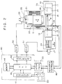
- FIG. 2 there is shown a numerically controlled grinding machine embodying the concept of the present invention.
- This machine has a bed 10 on which a table 11 is placed.
- a headstock 12 supporting a spindle 13 and a tailstock 15 are mounted on the table 11.
- the table 11 is connected to a servomotor 17 via a feed screw mechanism 24 so as to be moved in a Z-axis direction that is parallel to the rotational axis Os of the spindle 13.
- a workpiece W is rotatably held between a center 14 of the spindle 13 and a center 16 of the tailstock 15.
- Disposed on the bed 10 is a measuring device 19 for measuring the diameter of the workpiece W.
- a grinding wheel head 20 is mounted at the top rear of the bed 10 in such a way that the wheel head 17 is movable in an X-axis direction that is perpendicular to the Z-axis direction
- the wheel head 20 is connected to a servomotor 23 via a feed screw mechanism 25 so as to be moved by the servomotor 23.
- a grinding wheel G is supported on the wheel head 20 and is driven by a motor 21.
- the table 11 is further provided with a truing tool or truer 18 for truing a grinding surface of the grinding wheel G.
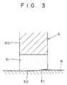
- the grinding wheel G is composed of a circular wheel core 60 and a grinding layer 61 bonded on the circumference of the wheel core 60, as viewed in FIG. 3. In the grinding layer 61, numerous CBN grains are bonded to one another using vitrified bond.
- the grinding wheel G has a straight grinding surface 30 and a tapered grinding surface 31 successive thereto.
- the straight grinding surface 30 extends parallel to the rotational axis of the workpiece W, while the tapered grinding surface 31 extends inclined with respect to the rotational axis of the workpiece W, at an acute angle.
- the numeral 40 denotes a numerical controller which is composed of a central processing unit 45 (referred to as "CPU” hereinafter), a memory 44 and interfaces 41, 42, 43.
- CPU central processing unit
- An operator's panel 80 is connected to the CPU 45 through the interface 41 to input machining program data, machining condition data and so on.
- Drive circuits 50 and 51 are also connected to the CPU through the interface 42 to drive the servomotors 23 and 17, respectively.
- the measuring device 19 is connected to the CPU 45 through the interface 43 and a sequence controller 46.
- the memory 44 there are formed plural data memory areas such as a machining program memory area and a machining condition data memory area.
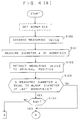
- FIGs. 4(a) and (b) are the routine of a grinding program for controlling a grinding operation.
- the measuring device 19 is advanced toward the workpiece W, at step S100.
- step S101 follows to measure the diameter d of the workpiece W by the measuring device 19.
- Step S102 is then executed wherein the measuring device 19 is retracted to the original position. It is judged at next step S103 whether or not the measured diameter d is equal to the blank diameter of the workpiece ground in the last grinding operation. If the judgement is "YES”, the process proceeds to step S104. If the judgement is "NO”, the process proceeds to step S105 described later.
- step S104 it is judged at step S104 whether or not the parameter n representing the number of the workpieces which have been ground after the last truing operation is equal to or larger than value N.
- This value N indicates the number of the ground workpieces which would be reached when the length of the straight grinding surface 30 in the direction of the rotational axis Os of the workpiece W becomes shorter than 2 millimeters.
- the value N may be determined empirically or experimentally. If the parameter n indicates equal to or larger than the value N, the process proceeds to step S105. If the parameter n is smaller than the value N, the process proceeds to step S108 described later.
- the angle ⁇ to be formed between the rotational axis Os of the workpiece W and the tapered grinding surface 31 is selected by reference to the diameter d of the workpiece W measured at step S101.
- the angles ⁇ of the tapered grinding surface 31 corresponding to the diameters d of the workpiece W are stored in a data table of the memory 44, as shown in FIG. 6. It is noted that the angle ⁇ is decreased with increase of the diameter d.
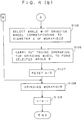
- the grinding wheel G is trued by the truer 18 so that the straight grinding surface 30 have a length equal to or larger than 5 millimeters in the direction of the rotational axis of the workpiece W and that tapered grinding surface 31 forms the selected angle ⁇ with the rotational axis Os of the workpiece W. Then, the parameter n is reset to zero at step S107.
- the workpiece W is ground by the grinding wheel G.
- the table 11 is moved to that position where the left end of the workpiece W faces the grinding wheel G.
- the grinding wheel G and the workpiece W are rotated and the wheel head 20 is advanced toward the workpiece W by a predetermined amount.
- the table 11 is traversed toward the left as viewed in FIG. 2 in a direction of the rotational axis of the workpiece W.
- the tapered grinding surface 31 carries out a rough grinding on the outer surface of the workpiece W, at the same time of which the straight grinding surface 30 following the tapered one 31 carries out a fine grinding on the roughly ground outer surface.
- the table 11 is stopped when the grinding wheel G has passed the right end of the workpiece W.
- the wheel head 20 is then retracted to its original position.
- the grinding operation for the cylindrical surface of the workpiece W is thus completed.
- the parameter n is increased by one.
- step S106 The truing operation at step S106 is executed in accordance with those steps illustrated in detail in FIG. 5. Firstly, at step S200, the table 11 is moved in Z-axis direction until the the truer 18 is positioned at the left of the left end of the grinding wheel G, as shown in FIG. 7. At step S201, the feed amount A of the wheel head 20 is calculated and the wheel head 20 is advanced toward the workpiece W by the calculated amount of A.
- step S202 the table 11 is moved to right by a distance 21 which is equal to or longer than 5 millimeters.
- the servomotors 23 and 17 are simultaneously controlled, whereby the wheel head 20 is advanced by distance of X as the table 11 is moved to right by distance of Z2.
- Step S204 is next reached to move back the wheel head 20 by the distance of (A+X) to return the same its original position.
- step S205 the table 11 is moved to the left by the distance of (Z1+Z2) to be returned its original position.
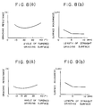
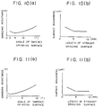
- FIGs. 8(a), 9(a), 10(a) and 11(a) there are shown the relationship between inclined angles ⁇ of the tapered grinding surfaces 31 and the grinding resistance.
- the diameter and width of the grinding wheel G are 400 millimeters and 10 millimeters, respectively
- the length of the straight grinding surface 30 in the direction of the rotational axis of the workpiece W is 5 millimeters
- the peripheral speed of the grinding wheel G is 160m/s.
- the grinding resistance is minimized at the angle of 20°, as illustrated in FIG. 8(a).
- the roundness of the workpiece W can be improved when the angle ⁇ between the tapered grinding surface 31 and the rotational axis of the workpiece W is chosen to be 20°.
- the grinding resistance is minimized at the angle of 15°, as illustrated in FIG. 9(a).
- the grinding resistance is minimized at the angle of 5°, as illustrated in FIG. 10(a).
- the grinding resistance is minimized at the angle of 1°, as illustrated in FIG. 11(a). Therefore, if the diameter of the workpiece exists in the range between 5 millimeters and 100 millimeters, the inclined angle of the tapered grinding surface 31 is selected to be decreased with the increases of the diameter of the workpiece between 1° and 20°.
- FIGs. 8(b), 9(b), 10(b) and 11(b) show the relationship between the lengths of the straight grinding surfaces 30 in the direction of the rotational axis of the workpiece W and the surface roughness of the ground workpiece W.
- the diameter and width of the grinding wheel G are 400 millimeters and 10 millimeters, respectively, and the peripheral speed of the grinding wheel G is 160m/s.
- the diameters of the workpieces W used in cases shown in FIGs. 8(b), 9(b), 10(b) and 11(b) correspond to those used in cases shown in FIGs. 8(a), 9(a), 10(a) and 11(a).
- the surface roughness of the workpiece W can be improved when the length of the straight grinding surface 30 is equal to or longer than 5 millimeters.
- the operator may change the grinding wheel to another one in which the tapered grinding surface has such a selected angle.
- the desired angle ⁇ of the tapered grinding surface 31 is selected based upon the diameter of the workpiece.
- the grinding resistance can be decreased and the roundness of the workpiece can be improved.
- the surface roughness of the workpiece can be improved by setting the length of the straight grinding surface 30 in the direction of the rotational axis of the workpiece to a suitable value, regardless of the diameter of the workpiece.
- the traverse feed of the workpiece relative to the grinding wheel may be repeated several times if the grinding allowance of a workpiece is considerably large. Further, subsequently to the first or final traverse feed with a grinding infeed depth, one additional traverse feed may be carried out with the grinding infeed depth being not given, for improvement in the surface roughness.
- a measuring device is used to measure the diameter of a workpiece prior to the actual grinding thereof, the present invention is not limited to using such measuring device.
- the diameter of a workpiece to be machined may otherwise be obtained from a numerical control data being stored in the numerical controller, so that the angle to be formed between the tapered grinding surface and the rotational axis of the workpiece can be selected by reference to the stored diameter of the workpiece.
- steps S100-S102 may be replaced by a single or more steps of retrieving the diameter of a workpiece to be ground next, from the memory 44 which has stored numerical control data for the workpiece, and the workpiece diameter used at step S103 may be that retrieved at such single or more steps. Further, the retrieved diameter may be the blank diameter or a target or finished diameter of the workpiece.
Landscapes
- Engineering & Computer Science (AREA)
- Mechanical Engineering (AREA)
- Grinding Of Cylindrical And Plane Surfaces (AREA)
Description
- The present invention relates to a method and a machine for grinding a cylindrical surface of a workpiece with a grinding wheel.
- In a conventional grinding machine for traverse feed grinding, a grinding wheel has a straight grinding surface and a tapered grinding surface successive thereto. The straight grinding surface is parallel to the rotational axis of a workpiece to be ground, while the tapered grinding surface forms a predetermined angle with the rotational axis of the workpiece. When a cylindrical surface of the workpiece is ground with this grinding wheel, the grinding wheel is advanced at the position corresponding to one end of the workpiece so as to be fed into the workpiece. Then, the workpiece is traversed in a direction of its rotational axis. During this operation, the tapered grinding surface carries out a rough grinding and subsequently, the straight grinding surface carries out a fine grinding.
- Since the grinding machine having such a grinding wheel can complete the grinding operation for the cylindrical surface of the workpiece through only one traverse feed, the time required for the grinding operation can be shortened. However, there are involved some problems regarding the above-mentioned grinding wheel.
- In case where the angle which the tapered grinding surface and the rotational axis of the workpiece W make is too large, the width A of the tapered grinding surface which acts on the workpiece W is narrow, as shown in FIG. 1(a). Under this condition, excessive load acts on each grain of the tapered grinding surface, whereby abrasion of the grinding wheel G and grinding resistance become large. Conversely, in case where the angle is too small, the width A is wide, as illustrated in FIG. 1(b). Each grain on the tapered grinding surface is subjected to a slight load which causes the grinding wheel G to slide or slip on the cylindrical surface of the workpiece W. Since these phenomenons influence roundness and straightness of the ground workpiece W, it is difficult to attain desired roundness and straightness.
- Further, the straight grinding surface of the grinding wheel G works to smooth the cylindrical surface of the workpiece W. If the length of the straight grinding surface is too short, it is difficult to attain a desired surface roughness.
- From the document US-A-5 048 235 a grinding method is described in case of which a cylindrical surface is ground in one grinding operation by means of two grinding surfaces having a specific angle with respect to each other. During grinding, the workpiece is first roughly ground by the first grinding surface which is inclined with respect to the rotational axis of the workpiece, and is then precision-ground by the subsequent second grinding surface arranged in parallel to the rotational axis of the workpiece. By this method, the object underlying this document is solved to enable changing the effective grinding rate of the organic bonded grinding wheel during the grinding of a workpiece where a vastly different wheel performance is required in different parts of the grind cycle. By this way, rough and finish grinding can be done in one cycle.
- According to the method described in this document, the grinding wheel or the grinding surfaces can be trued when grinding the workpiece to obtain a high grinding rate. By doing so, the grinding surfaces are kept in an optimum state during the entire grinding operation.
- The object underlying the invention is to provide a method and a machine capable of improving the surface roughness of a workpiece. According to the invention, this object is achieved by means of the features of
claims 1 and 6. - Various features and many of the attendant advantages of the present invention will be readily appreciated as the same becomes better understood by reference to the following detailed description of the preferred embodiment when considered in connection with the accompanying drawings, in which:
- FIGs. 1 (a) and (b) are explanatory views showing situations wherein a grinding wheel is grinding a workpiece in the prior art;
- FIG. 2 is a plan view of a grinding machine according to the present invention, also illustrating a block diagram of an electric control system therefor;
- FIG. 3 is an enlarged fragmentary sectional view of a grinding wheel used in the present invention;
- FIGs. 4(a) and (b) are flowcharts illustrating a grinding program executed by a CPU shown in FIG. 2;
- FIG. 5 is a flowchart illustrating in detail a truing step shown in FIG. 4(b);
- FIG. 6 is a data table indicating the angles of a tapered grinding surface which are to be selected in dependance upon changes in diameter of the workpiece;
- FIG. 7 is an explanatory view showing the movement of the truing tool relative to the grinding wheel in a truing operation;
- FIGs. 8 (a), 9(a), 10(a) and 11(a) are graphs showing the relationship between the angles of the tapered grinding surface formed with the rotational axis of the workpiece and grinding resistances;
- FIGs. 8(b), 9(b), 10(b) and 11(b) are graphs showing the relationship between the lengths of a straight grinding surface and the surface roughness of the ground workpiece;
- Referring now to the drawings and particularly to FIG. 2 thereof, there is shown a numerically controlled grinding machine embodying the concept of the present invention. This machine has a
bed 10 on which a table 11 is placed. Aheadstock 12 supporting aspindle 13 and atailstock 15 are mounted on the table 11. The table 11 is connected to aservomotor 17 via afeed screw mechanism 24 so as to be moved in a Z-axis direction that is parallel to the rotational axis Os of thespindle 13. A workpiece W is rotatably held between acenter 14 of thespindle 13 and acenter 16 of thetailstock 15. Disposed on thebed 10 is ameasuring device 19 for measuring the diameter of the workpiece W. - A
grinding wheel head 20 is mounted at the top rear of thebed 10 in such a way that thewheel head 17 is movable in an X-axis direction that is perpendicular to the Z-axis direction Thewheel head 20 is connected to aservomotor 23 via afeed screw mechanism 25 so as to be moved by theservomotor 23. A grinding wheel G is supported on thewheel head 20 and is driven by amotor 21. The table 11 is further provided with a truing tool or truer 18 for truing a grinding surface of the grinding wheel G. - The grinding wheel G is composed of a
circular wheel core 60 and agrinding layer 61 bonded on the circumference of thewheel core 60, as viewed in FIG. 3. In thegrinding layer 61, numerous CBN grains are bonded to one another using vitrified bond. The grinding wheel G has a straight grindingsurface 30 and atapered grinding surface 31 successive thereto. Thestraight grinding surface 30 extends parallel to the rotational axis of the workpiece W, while thetapered grinding surface 31 extends inclined with respect to the rotational axis of the workpiece W, at an acute angle. - Turning back to FIG. 2, the
numeral 40 denotes a numerical controller which is composed of a central processing unit 45 (referred to as "CPU" hereinafter), amemory 44 andinterfaces panel 80 is connected to theCPU 45 through theinterface 41 to input machining program data, machining condition data and so on.Drive circuits interface 42 to drive theservomotors measuring device 19 is connected to theCPU 45 through theinterface 43 and asequence controller 46. - In the
memory 44, there are formed plural data memory areas such as a machining program memory area and a machining condition data memory area. - The operation of the grinding machine in grinding the workpiece according to the present invention will now be described with reference to to the flowcharts shown in FIGs. 4(a), (b) and 5.
- FIGs. 4(a) and (b) are the routine of a grinding program for controlling a grinding operation. When a workpiece W is set between the
headstock 12 and thetailstock 15, and when the operator pushes one of buttons (a grinding start button) on the operator'spanel 80, themeasuring device 19 is advanced toward the workpiece W, at step S100. Next step S101 follows to measure the diameter d of the workpiece W by themeasuring device 19. Step S102 is then executed wherein themeasuring device 19 is retracted to the original position. It is judged at next step S103 whether or not the measured diameter d is equal to the blank diameter of the workpiece ground in the last grinding operation. If the judgement is "YES", the process proceeds to step S104. If the judgement is "NO", the process proceeds to step S105 described later. - Subsequently, it is judged at step S104 whether or not the parameter n representing the number of the workpieces which have been ground after the last truing operation is equal to or larger than value N. This value N indicates the number of the ground workpieces which would be reached when the length of the
straight grinding surface 30 in the direction of the rotational axis Os of the workpiece W becomes shorter than 2 millimeters. The value N may be determined empirically or experimentally. If the parameter n indicates equal to or larger than the value N, the process proceeds to step S105. If the parameter n is smaller than the value N, the process proceeds to step S108 described later. - At step S105, the angle θ to be formed between the rotational axis Os of the workpiece W and the tapered grinding
surface 31 is selected by reference to the diameter d of the workpiece W measured at step S101. The angles θ of the tapered grindingsurface 31 corresponding to the diameters d of the workpiece W are stored in a data table of thememory 44, as shown in FIG. 6. It is noted that the angle θ is decreased with increase of the diameter d. At next step S106, the grinding wheel G is trued by the truer 18 so that the straight grindingsurface 30 have a length equal to or larger than 5 millimeters in the direction of the rotational axis of the workpiece W and that tapered grindingsurface 31 forms the selected angle θ with the rotational axis Os of the workpiece W. Then, the parameter n is reset to zero at step S107. - At next step S108, the workpiece W is ground by the grinding wheel G. At first, the table 11 is moved to that position where the left end of the workpiece W faces the grinding wheel G. The grinding wheel G and the workpiece W are rotated and the
wheel head 20 is advanced toward the workpiece W by a predetermined amount. After that, the table 11 is traversed toward the left as viewed in FIG. 2 in a direction of the rotational axis of the workpiece W. During this operation, the tapered grindingsurface 31 carries out a rough grinding on the outer surface of the workpiece W, at the same time of which the straight grindingsurface 30 following the tapered one 31 carries out a fine grinding on the roughly ground outer surface. The table 11 is stopped when the grinding wheel G has passed the right end of the workpiece W. Thewheel head 20 is then retracted to its original position. The grinding operation for the cylindrical surface of the workpiece W is thus completed. Thereafter, at step S109, the parameter n is increased by one. - The truing operation at step S106 is executed in accordance with those steps illustrated in detail in FIG. 5. Firstly, at step S200, the table 11 is moved in Z-axis direction until the the truer 18 is positioned at the left of the left end of the grinding wheel G, as shown in FIG. 7. At step S201, the feed amount A of the
wheel head 20 is calculated and thewheel head 20 is advanced toward the workpiece W by the calculated amount of A. - Next, at step S202, the table 11 is moved to right by a
distance 21 which is equal to or longer than 5 millimeters. At next step S203, theservomotors wheel head 20 is advanced by distance of X as the table 11 is moved to right by distance of Z2. Here, the distances Z2 and X are calculated by the following equations:
- Where the known value L is the width of the grinding wheel G.
- During this operation, the grinding wheel G is trued to a desired shape, wherein the straight grinding
surface 30 have length equal to or larger than 5 millimeters in the direction of rotational axis of the workpiece W while the tapered grindingsurface 31 forms the selected angle θ with the rotational axis of the workpiece W. Step S204 is next reached to move back thewheel head 20 by the distance of (A+X) to return the same its original position. Thereafter, at step S205, the table 11 is moved to the left by the distance of (Z1+Z2) to be returned its original position. - In FIGs. 8(a), 9(a), 10(a) and 11(a), there are shown the relationship between inclined angles θ of the tapered grinding surfaces 31 and the grinding resistance. In any case, the diameter and width of the grinding wheel G are 400 millimeters and 10 millimeters, respectively, the length of the straight grinding
surface 30 in the direction of the rotational axis of the workpiece W is 5 millimeters, and the peripheral speed of the grinding wheel G is 160m/s. In case where the diameter of the workpiece W is 5 millimeters, the grinding resistance is minimized at the angle of 20°, as illustrated in FIG. 8(a). Namely, since the difference of the amount by which the workpiece W runs off from the grinding wheel G becomes small between the both ends and the middle portion of the workpiece W, the roundness of the workpiece W can be improved when the angle θ between the tapered grindingsurface 31 and the rotational axis of the workpiece W is chosen to be 20°. In case where the diameter of the workpiece W is 25 millimeters, the grinding resistance is minimized at the angle of 15°, as illustrated in FIG. 9(a). In case where the diameter of the workpiece W is 45 millimeters, the grinding resistance is minimized at the angle of 5°, as illustrated in FIG. 10(a). Further in case where the diameter of the workpiece W is 100 millimeters, the grinding resistance is minimized at the angle of 1°, as illustrated in FIG. 11(a). Therefore, if the diameter of the workpiece exists in the range between 5 millimeters and 100 millimeters, the inclined angle of the tapered grindingsurface 31 is selected to be decreased with the increases of the diameter of the workpiece between 1° and 20°. - FIGs. 8(b), 9(b), 10(b) and 11(b) show the relationship between the lengths of the straight grinding surfaces 30 in the direction of the rotational axis of the workpiece W and the surface roughness of the ground workpiece W. In any case, the diameter and width of the grinding wheel G are 400 millimeters and 10 millimeters, respectively, and the peripheral speed of the grinding wheel G is 160m/s. The diameters of the workpieces W used in cases shown in FIGs. 8(b), 9(b), 10(b) and 11(b) correspond to those used in cases shown in FIGs. 8(a), 9(a), 10(a) and 11(a). In any case, the surface roughness of the workpiece W can be improved when the length of the straight grinding
surface 30 is equal to or longer than 5 millimeters. - Although the angle θ varied depending on the diameter of the workpiece is formed by truing the grinding wheel in the present embodiment, the operator may change the grinding wheel to another one in which the tapered grinding surface has such a selected angle.
- As described above, in the present invention, the desired angle ϑ of the tapered grinding
surface 31 is selected based upon the diameter of the workpiece. As a result, the grinding resistance can be decreased and the roundness of the workpiece can be improved. Further, the surface roughness of the workpiece can be improved by setting the length of the straight grindingsurface 30 in the direction of the rotational axis of the workpiece to a suitable value, regardless of the diameter of the workpiece. - In the traverse grinding operation, the traverse feed of the workpiece relative to the grinding wheel may be repeated several times if the grinding allowance of a workpiece is considerably large. Further, subsequently to the first or final traverse feed with a grinding infeed depth, one additional traverse feed may be carried out with the grinding infeed depth being not given, for improvement in the surface roughness.
- Although in the embodiment, a measuring device is used to measure the diameter of a workpiece prior to the actual grinding thereof, the present invention is not limited to using such measuring device. The diameter of a workpiece to be machined may otherwise be obtained from a numerical control data being stored in the numerical controller, so that the angle to be formed between the tapered grinding surface and the rotational axis of the workpiece can be selected by reference to the stored diameter of the workpiece.
- In this modified case, steps S100-S102 may be replaced by a single or more steps of retrieving the diameter of a workpiece to be ground next, from the
memory 44 which has stored numerical control data for the workpiece, and the workpiece diameter used at step S103 may be that retrieved at such single or more steps. Further, the retrieved diameter may be the blank diameter or a target or finished diameter of the workpiece.
Claims (10)
- A method of grinding a cylindrical surface of a workpiece (W) with a grinding wheel (G) having a first grinding surface (30) parallel to the rotational axis of the workpiece (W) and a second grinding surface (31) successive to the first grinding surface (30) and inclined with respect to the rotational axis of the workpiece (W), wherein the cylindrical surface is firstly ground by the second grinding surface (31) and subsequently ground by the first grinding surface (30), wherein said grinding wheel (G) is moved relative to said workpiece (W) in a direction of the rotational axis of said workpiece (W) to grind the cylindrical surface of said workpiece (W) successively with said second and first grinding surfaces (31, 30),
characterized by
selecting an angle (θ) to be formed between said second grinding surface (31) and the rotational axis of said workpiece (W) based upon a diameter of said workpiece (W) to be ground; and forming the selected angle (θ) between said second grinding surface (31) and the rotational axis of said workpiece (W) before grinding said workpiece (W) while maintaining said first grinding surface in parallel with the rotational axis of said workpiece (W), wherein said selected angle (θ) formed between said second grinding surface (31) and the rotational axis of said workpiece (W) is made smaller with an increase in the diameter (d) of said workpiece (W). - A method of grinding a cylindrical surface of a workpiece with a grinding wheel as set forth in claim 1, wherein said selected angle (θ) is in a range between 1° and 20° when the diameter of the workpiece (W) ranges between 5mm and 100mm.
- A method of grinding a cylindrical surface of a workpiece with a grinding wheel as set forth in claim 1, wherein the length of said first grinding surface (30) in the direction of the rotational axis of said workpiece (W) is at least 5mm.
- A method of grinding a cylindrical surface of a workpiece with a grinding wheel as set forth in claim 1, wherein said selected angle (θ) is formed by truing said grinding wheel.
- A method of grinding a cylindrical surface of a workpiece with a grinding wheel as set forth in claim 1, wherein said method further comprises the step of measuring a diameter of the workpiece (W) and wherein said step of selecting an angle (θ) is performed based upon the diameter of said workpiece (W) measured at the measuring step.
- A machine for grinding a cylindrical surface of a workpiece (W) with a grinding wheel (G) having a first grinding surface (30) parallel to the rotational axis of the workpiece (W) and a second grinding surface (31) successive to the first grinding surface (30) and inclined with respect to the rotational axis of the workpiece (W), said machine including a workpiece support table rotatably carrying said workpiece (W) and movable in parallel with the rotational axis of said workpiece (W), a wheel head (20) rotatably carrying said grinding wheel (G) and movable perpendicularly to the rotational axis of said workpiece (W), feed means connected to said table (11) and said wheel head (20), and control means for controlling said feed means, so that the cylindrical surface is firstly ground by the second grinding surface (31) and subsequently ground by the first grinding surface (30),
characterized by
means for selecting an angle (θ) to be formed between said second grinding surface (31) and the rotational axis of said workpiece (W) based upon a diameter (d) of said workpiece (W) to be ground; and
means for forming the selected angle (θ) between said second grinding surface (31) and the rotational axis of said workpiece (W) before grinding said workpiece (W) while maintaining said first grinding surface (30) in parallel with the rotational axis of said workpiece (W), wherein said selected angle (θ) formed between said second grinding surface (31) and the rotational axis of said workpiece (W) is made smaller with an increase in the diameter (d) of said workpiece (W). - A machine for grinding a cylindrical surface of a workpiece with a grinding wheel as set forth in claim 6, wherein said selected angle (θ) is in a range between 1° and 20° when the diameter of the workpiece (W) ranges between 5mm and 100mm.
- A machine for grinding a cylindrical surface of a workpiece with a grinding wheel as set forth in claim 6, wherein the length of said first grinding surface (30) in the direction of the rotational axis of said workpiece (W) is at least 5mm.
- A machine for grinding a cylindrical surface of a workpiece with a grinding wheel as set forth in claim 6, wherein said machine further comprises truing means for truing said grinding wheel (G), and wherein said selected angle (θ) is formed by truing said grinding wheel (G) by said truing means.
- A machine for grinding a cylindrical surface of a workpiece with a grinding wheel as set forth in claim 6, wherein said machine further comprises measuring means for measuring a diameter of the workpiece (W), and wherein said selecting means selects the angle based upon a diameter measured by said measuring means.
Applications Claiming Priority (2)
| Application Number | Priority Date | Filing Date | Title |
|---|---|---|---|
| JP26214092 | 1992-09-30 | ||
| JP262140/92 | 1992-09-30 |
Publications (2)
| Publication Number | Publication Date |
|---|---|
| EP0590640A1 EP0590640A1 (en) | 1994-04-06 |
| EP0590640B1 true EP0590640B1 (en) | 1997-08-06 |
Family
ID=17371614
Family Applications (1)
| Application Number | Title | Priority Date | Filing Date |
|---|---|---|---|
| EP93115726A Expired - Lifetime EP0590640B1 (en) | 1992-09-30 | 1993-09-29 | Method and machine for grinding a workpiece |
Country Status (3)
| Country | Link |
|---|---|
| US (1) | US5533931A (en) |
| EP (1) | EP0590640B1 (en) |
| DE (1) | DE69312838T2 (en) |
Families Citing this family (16)
| Publication number | Priority date | Publication date | Assignee | Title |
|---|---|---|---|---|
| DE4436200A1 (en) * | 1994-10-11 | 1996-04-18 | Patrick Schulz | Eliminating irregularities from tyre running surfaces |
| IT1274498B (en) * | 1995-05-12 | 1997-07-17 | Balance Systems Srl | DEVICE AND COMMAND AND CONTROL PROCEDURE FOR A GRINDING MACHINE |
| US6144892A (en) * | 1996-02-08 | 2000-11-07 | Royal Master Grinders, Inc. | Gauging system |
| JP3197482B2 (en) * | 1996-03-08 | 2001-08-13 | ワイケイケイ株式会社 | Manufacturing method of ferrule for optical fiber connector |
| DE945216T1 (en) * | 1998-03-25 | 2000-06-08 | Unova U.K. Ltd., Aylesbury | Notch grinding tool |
| US6227938B1 (en) | 1998-09-08 | 2001-05-08 | Royal Masters Grinders, Inc. | Guidewire position locator |
| GB2361445A (en) * | 1999-02-03 | 2001-10-24 | Unova Uk Ltd | Angle head grinding |
| DE10034079A1 (en) * | 2000-07-13 | 2002-01-24 | Heidenhain Gmbh Dr Johannes | Device and method for controlling a machine tool |
| US6835115B2 (en) * | 2000-12-22 | 2004-12-28 | Rolltest Oy | Grinding method |
| US6852006B1 (en) | 2002-06-06 | 2005-02-08 | Glebar Company, Inc. | Automated system for precision grinding of feedstock |
| DE102004009352B4 (en) * | 2004-02-26 | 2006-01-19 | Thyssen Krupp Automotive Ag | Device for producing a finished contour of a workpiece by grinding and method thereto |
| JP5058460B2 (en) * | 2005-07-11 | 2012-10-24 | Ntn株式会社 | LATHE WITH POLISHING DEVICE AND SHAFT WORK PROCESSING METHOD USING THE SAME |
| KR100996876B1 (en) * | 2005-12-14 | 2010-11-29 | 비티티 코퍼레이션 | Grinding device used for neck grinding device and neck grinding device |
| EP3019309A4 (en) * | 2013-07-08 | 2017-08-09 | Saint-Gobain Abrasives, Inc. | Method for forming a workpiece |
| US10144111B2 (en) | 2016-05-05 | 2018-12-04 | Joseph Peter Gasparino, Jr. | Bench grinder safety and monitoring system |
| CN109277885A (en) * | 2018-10-15 | 2019-01-29 | 哈尔滨理工大学 | A kind of grinding method of tungsten carbide coating thin-walled guide cylinder |
Family Cites Families (14)
| Publication number | Priority date | Publication date | Assignee | Title |
|---|---|---|---|---|
| US4219972A (en) * | 1977-10-17 | 1980-09-02 | Seiko Seiki Kabushiki Kaisha | Control apparatus for a grinding machine |
| US4337599A (en) * | 1979-04-03 | 1982-07-06 | Toyoda Koki Kabushiki Kaisha | Method of shoulder grinding |
| DE3136441C2 (en) * | 1981-09-14 | 1986-06-26 | Fortuna-Werke Maschinenfabrik Gmbh, 7000 Stuttgart | Device for cylindrical grinding of workpieces |
| JPS58132460A (en) * | 1982-01-29 | 1983-08-06 | Toyoda Mach Works Ltd | Numerical controller for angular grinder |
| US4492061A (en) * | 1982-03-05 | 1985-01-08 | Energy-Adaptive Grinding, Inc. | Control system for grinding apparatus |
| CH654782A5 (en) * | 1982-03-19 | 1986-03-14 | Maag Zahnraeder & Maschinen Ag | METHOD AND DEVICE FOR COMPENSATING THE WEAR OF AN ADJUSTABLE GRINDING WHEEL DRESSING TOOL. |
| EP0161674B1 (en) * | 1984-05-16 | 1991-02-20 | Toyoda Koki Kabushiki Kaisha | Numerical control grinding machine |
| IT1191688B (en) * | 1986-03-20 | 1988-03-23 | Giustina International Spa | CYLINDER GRINDING MACHINE WITH SIGNIFICANT BODIES AND DIMENSIONAL AND SURFACE CONTROL |
| DE3737641A1 (en) * | 1987-10-19 | 1989-04-27 | Fortuna Werke Maschf Ag | PROCESS FOR EXTERNAL ROUND GRINDING OF WORKPIECES |
| US5048235A (en) * | 1988-11-15 | 1991-09-17 | Smith Roderick L | Predictive high wheel speed grinding system |
| JPH04141355A (en) * | 1990-09-28 | 1992-05-14 | Toyoda Mach Works Ltd | Grinding method |
| EP0480269A3 (en) * | 1990-09-28 | 1993-03-03 | Toyoda Koki Kabushiki Kaisha | Numerically controlled grinding machine |
| JPH04348869A (en) * | 1991-03-28 | 1992-12-03 | Toyoda Mach Works Ltd | Correction device for angular grinding wheel |
| JPH05185368A (en) * | 1992-01-16 | 1993-07-27 | Toyoda Mach Works Ltd | Grinding wheel shaping method |
-
1993
- 1993-09-29 EP EP93115726A patent/EP0590640B1/en not_active Expired - Lifetime
- 1993-09-29 DE DE69312838T patent/DE69312838T2/en not_active Expired - Lifetime
-
1995
- 1995-09-20 US US08/531,058 patent/US5533931A/en not_active Expired - Lifetime
Also Published As
| Publication number | Publication date |
|---|---|
| DE69312838T2 (en) | 1998-01-29 |
| US5533931A (en) | 1996-07-09 |
| DE69312838D1 (en) | 1997-09-11 |
| EP0590640A1 (en) | 1994-04-06 |
Similar Documents
| Publication | Publication Date | Title |
|---|---|---|
| EP0590640B1 (en) | Method and machine for grinding a workpiece | |
| JP3467807B2 (en) | Grinding equipment | |
| JP2637488B2 (en) | Numerically controlled grinding machine | |
| JP2001105289A (en) | Method and device for controlling constant size working of machine tool | |
| JPH052458B2 (en) | ||
| US5766059A (en) | Method of grinding a workpiece | |
| EP1380385B1 (en) | Method of simultaneously grinding a plurality of grinding portions on a workpiece | |
| EP1621287B1 (en) | Method and apparatus for grinding cams with a re-entrant surface | |
| US5272843A (en) | Method and apparatus for truing a grinding wheel | |
| JP2786879B2 (en) | Internal grinding device | |
| EP0477732B1 (en) | Method and machine for grinding | |
| JPH1190799A (en) | Machine tool for crank pin machining and machining method for crank pin | |
| JP3162101B2 (en) | Dressing method for inner surface grinding wheel and dressing apparatus therefor | |
| JPH06134668A (en) | Grinding machine | |
| JP3404902B2 (en) | Grinding equipment | |
| JP3120578B2 (en) | Grinding equipment | |
| JP2002103188A (en) | End surface grinding method and end surface grinding device | |
| JP3812869B2 (en) | Cylindrical grinding method and apparatus | |
| JP7519212B2 (en) | Grinding method and grinding device | |
| JPH0899257A (en) | Grinding device | |
| JP3170938B2 (en) | Grinding method | |
| JPH068136A (en) | Polishing device | |
| JPH06278021A (en) | Grinding device | |
| JPH08314520A (en) | Numerically controlled grinder | |
| JPH06190696A (en) | Grinding device |
Legal Events
| Date | Code | Title | Description |
|---|---|---|---|
| PUAI | Public reference made under article 153(3) epc to a published international application that has entered the european phase |
Free format text: ORIGINAL CODE: 0009012 |
|
| AK | Designated contracting states |
Kind code of ref document: A1 Designated state(s): DE FR GB |
|
| 17P | Request for examination filed |
Effective date: 19940916 |
|
| 17Q | First examination report despatched |
Effective date: 19950324 |
|
| GRAG | Despatch of communication of intention to grant |
Free format text: ORIGINAL CODE: EPIDOS AGRA |
|
| GRAH | Despatch of communication of intention to grant a patent |
Free format text: ORIGINAL CODE: EPIDOS IGRA |
|
| GRAH | Despatch of communication of intention to grant a patent |
Free format text: ORIGINAL CODE: EPIDOS IGRA |
|
| GRAA | (expected) grant |
Free format text: ORIGINAL CODE: 0009210 |
|
| AK | Designated contracting states |
Kind code of ref document: B1 Designated state(s): DE FR GB |
|
| REF | Corresponds to: |
Ref document number: 69312838 Country of ref document: DE Date of ref document: 19970911 |
|
| ET | Fr: translation filed | ||
| PLBE | No opposition filed within time limit |
Free format text: ORIGINAL CODE: 0009261 |
|
| STAA | Information on the status of an ep patent application or granted ep patent |
Free format text: STATUS: NO OPPOSITION FILED WITHIN TIME LIMIT |
|
| 26N | No opposition filed | ||
| REG | Reference to a national code |
Ref country code: GB Ref legal event code: IF02 |
|
| PGFP | Annual fee paid to national office [announced via postgrant information from national office to epo] |
Ref country code: GB Payment date: 20081001 Year of fee payment: 16 |
|
| GBPC | Gb: european patent ceased through non-payment of renewal fee |
Effective date: 20090929 |
|
| PG25 | Lapsed in a contracting state [announced via postgrant information from national office to epo] |
Ref country code: GB Free format text: LAPSE BECAUSE OF NON-PAYMENT OF DUE FEES Effective date: 20090929 |
|
| PGFP | Annual fee paid to national office [announced via postgrant information from national office to epo] |
Ref country code: DE Payment date: 20120927 Year of fee payment: 20 Ref country code: FR Payment date: 20120926 Year of fee payment: 20 |
|
| REG | Reference to a national code |
Ref country code: DE Ref legal event code: R071 Ref document number: 69312838 Country of ref document: DE |
|
| PG25 | Lapsed in a contracting state [announced via postgrant information from national office to epo] |
Ref country code: DE Free format text: LAPSE BECAUSE OF EXPIRATION OF PROTECTION Effective date: 20131001 |