EP0590687A1 - Einrichtung und Verfahren zum Verbinden einer Quelle mit durch Null gehender Wechselspannung mit einer Wechselspannungslast-Leitung und zum Trennen derselben von der Leitung - Google Patents
Einrichtung und Verfahren zum Verbinden einer Quelle mit durch Null gehender Wechselspannung mit einer Wechselspannungslast-Leitung und zum Trennen derselben von der Leitung Download PDFInfo
- Publication number
- EP0590687A1 EP0590687A1 EP93115943A EP93115943A EP0590687A1 EP 0590687 A1 EP0590687 A1 EP 0590687A1 EP 93115943 A EP93115943 A EP 93115943A EP 93115943 A EP93115943 A EP 93115943A EP 0590687 A1 EP0590687 A1 EP 0590687A1
- Authority
- EP
- European Patent Office
- Prior art keywords
- voltage
- time
- zero crossing
- window
- switch
- Prior art date
- Legal status (The legal status is an assumption and is not a legal conclusion. Google has not performed a legal analysis and makes no representation as to the accuracy of the status listed.)
- Withdrawn
Links
- 238000000034 method Methods 0.000 title claims abstract description 15
- 239000007787 solid Substances 0.000 claims description 8
- 230000000977 initiatory effect Effects 0.000 claims description 5
- 230000007704 transition Effects 0.000 description 5
- 230000001360 synchronised effect Effects 0.000 description 2
- 238000010438 heat treatment Methods 0.000 description 1
- 238000002955 isolation Methods 0.000 description 1
- 238000004519 manufacturing process Methods 0.000 description 1
- 230000001960 triggered effect Effects 0.000 description 1
Images


Classifications
-
- H—ELECTRICITY
- H03—ELECTRONIC CIRCUITRY
- H03K—PULSE TECHNIQUE
- H03K17/00—Electronic switching or gating, i.e. not by contact-making and –breaking
- H03K17/13—Modifications for switching at zero crossing
-
- H—ELECTRICITY
- H03—ELECTRONIC CIRCUITRY
- H03K—PULSE TECHNIQUE
- H03K17/00—Electronic switching or gating, i.e. not by contact-making and –breaking
- H03K17/16—Modifications for eliminating interference voltages or currents
Definitions
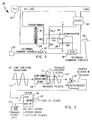
- the zero crossing switch (ZCS) 10 for example a zero crossing solid state relay, is shown connected in line between a zero crossing AC voltage source 11 and an AC driven load for closing and opening the AC load line in order to connect the AC voltage to and disconnect it from the load.
- the zero crossing switch is shown being controlled in accordance with the prior art by externally produced command signals 12 which will be described hereinafter in conjunction with FIGS 3A-3D.
- the relays' signal or performance specification requires that an ON signal be present in a predetermined period of time, for example 0.4 milliseconds, before the AC voltages zero crossing point ZC and continue through ZC for the relay to turn ON. It also specifically requires that the OFF signal be present for a predetermined period of time, for example .35 milliseconds, before ZC and continue through ZC for the relay to turn off. While most relay performance specifications do not address any required time period for the ON or OFF signal to remain present after ZC, applicants have found that, as a practical matter, such required periods exist.
- This performance window is indicated by dotted lines at PW in FIG 2. For purposes of simplicity, only one of the windows, for example the ON window, is illustrated. Thus, in accordance with prior art practice, in order to turn ON zero crossing switch 10 illustrated in FIG 1 at its zero crossing point ZC, an ON command signal 12 must be present at the beginning of performance window PW and continue throughout the duration of the window.
- the present invention recognizes and overcomes the problem just recited by providing internally controlled signals in response to externally produced command signals and a zero crossing AC voltage.
- these internally controlled command signals are used to control a zero crossing switch, in lieu of the externally produced command signals, in order to connect and disconnect a load line from its AC voltage source.
- these internally controlled command signals are produced such that either an ON or OFF signal, but not both, is present entirely throughout its associated specific window of time PW in order to prevent command signals from transitioning between ON and OFF states within any given window of time.
- the present invention provides for a DC controlled switching assembly for connecting a source of zero crossing AC voltage to and disconnecting it from an AC load line.
- This assembly includes a zero crossing switch connectable with the AC voltage source and AC load line for connecting the load line to and disconnecting it from said voltage source in response to ON and OFF command signals, but only if and when the appropriate command signal is present entirely throughout a window of time beginning a specific period of time prior to and including at least certain zero crossing points of the AC voltage.
- the assembly also includes signal providing means, connected with the switch and responsive to at least the AC voltage, for presenting to the switch internally controlled ON and OFF command signals such that either an ON or OFF signal, but not both, is present entirely throughout the specific window of time, thereby preventing command signals from switching between ON and OFF states within any given window of time.
- FIGS 4A and 4B depict a series 16A of internally produced command signals and a similar series is depicted in FIG 4B at 16B.
- Each of these series of internal command signals is shown synchronized in time with the externally controlled command signals 12 and with AC voltage 14.
- the shaded ON signal of series 16A extends through the entire extent of window PW, thereby insuring that the zero crossing switch 10 turns ON as the voltage 14 crosses its zero crossing point ZC.
- this ON pulse is initially triggered into production by the co-presence of an ON pulse forming part of the externally controlled command signals and a predetermined triggering point on the AC voltage 14.
- the left-most shaded ON pulse of series 12D in FIG 3D is present at the time the preselected triggering point T1 appears on the AC voltage wave form 14.
- the triggering point T1 is well ahead of the performance window PW and, hence, the internally produced shaded ON pulse 16A illustrated in FIG 4A is initiated well before the beginning of the performance window.
- Circuitry will be described hereinafter for insuring that the internally controlled shaded ON pulse continues uninterrupted throughout the performance window, even though the externally controlled series of external command signals transition between ON and OFF states, as exemplified by series 12D.
- DC controlled switching assembly 18 including a step down isolation transformer 24 having one side thereof connected to the AC load line and its other side to the inputs of a comparator circuit 26 through a voltage dividing resistance network 28.
- the output of the comparator is shown driving the clock input of a flip flop latch circuit 30 which has its control input connected to source 22 for receiving externally controlled command signals 12.
- the previously described internally controlled command signals 16 are generated at the output of flip flop latch circuit 30 which, as shown in FIG 5, is connected to the input of a cooperating zero crossing switch which also forms part of the overall assembly.
- the particular zero crossing switch shown is a zero crossing solid state relay 32, although it should be clear that the present invention is not limited to such a device.
- the triggering point T1 for initiating an internally controlled ON/OFF command signal 16 is established by the appropriate selection of resistors R3 and R4 which provide a referenced threshold for comparator circuit 26.
- Resistors R5 and R6 are selected to provide hysteresis in order to eliminate false triggering.
- the resistors R1 and R2 are selected to be equal so that the assembly can easily switch between 110 and 20 AC voltage.
- the triggering point T1 is set slightly below and on the positive-going side of the positive peak point of the AC wave form, as shown in FIG 2.
- the combination of comparator circuit 26 and flip flop latch 30 serves to maintain the presence of an internally generated ON or OFF command signal 16 for a full cycle from this triggering point, as stated previously.
- an externally controlled ON command signal 12 In order to turn on or close relay 32 in order to connect voltage source 20 to its load from a disconnected OFF condition, an externally controlled ON command signal 12 must be present at trigger point T1. Once that condition is met, the assembly immediately produces internally controlled ON command signal 16A for a full cycle and, therefore, entirely through the previously described performance window PW which, as stated, contains the zero crossing point of the voltage waveform.
- the relay 32 may be turned off from an ON state for disconnecting the AC voltage source from its load by generating an externally controlled OFF command signal 12 at trigger point T1 in order to produce a full cycle internally generated OFF command signal 16B.
- the negative input to the comparator reaches the voltage at the referenced threshold positive input, thereby causing the output of the comparator circuit to go low. This, in turn, drags the positive reference input with it, thereby preventing the comparator circuit from triggering again at point P1.
- the negative input of the comparator circuit is now equal to the reduced positive threshold input, thereby triggering the comparator circuit so that its output is again high in preparing it to go low again at the next trigger point T1.
- the output to comparator circuit 26 is connected to the clock input of flip flop latch circuit 30.
- the output of this later circuit latches into either a low (ON) or high (OFF) state at each trigger point depending on whether a low (ON) or high (OFF) external command 12 is present at its data input at the same time, as stated previously. Since the comparator circuit does not again switch from a high state to a low state until the next triggering signal T1, the output of the latch circuit remains fixed for that period of time which, in the example illustrated, is one full cycle. Thus, the internal ON/OFF command signal 16 is provided for a full cycle.
- the various circuit components making up this assembly are readily providable in view of the disclosure herein and that the present invention is not limited to a particular type of zero crossing switch such as the zero crossing solid state relay illustrated.
- the triggering point T1 can vary as can the duration of internally controlled ON/OFF command signals 16 so long as these later command signals extend entirely throughout the performance window PW of the particular zero crossing switch being used. With regard to duration, for example, the internally controlled ON/OFF command signals could be provided every half cycle.
- a DC controlled switching assembly 18' illustrated in FIG 7 may be provided to that end. Note that this latter assembly includes all of the components of assembly 18, along with a diode arrangement 40 disposed between the output of the transformer 24 and the input of the voltage divider network 28.
Landscapes
- Keying Circuit Devices (AREA)
- Electronic Switches (AREA)
Applications Claiming Priority (2)
| Application Number | Priority Date | Filing Date | Title |
|---|---|---|---|
| US07/956,921 US5410193A (en) | 1992-10-02 | 1992-10-02 | Apparatus and technique for connecting a source of zero crossing AC voltage to and disconnecting it from an AC load line |
| US956921 | 1992-10-02 |
Publications (1)
| Publication Number | Publication Date |
|---|---|
| EP0590687A1 true EP0590687A1 (de) | 1994-04-06 |
Family
ID=25498863
Family Applications (1)
| Application Number | Title | Priority Date | Filing Date |
|---|---|---|---|
| EP93115943A Withdrawn EP0590687A1 (de) | 1992-10-02 | 1993-10-02 | Einrichtung und Verfahren zum Verbinden einer Quelle mit durch Null gehender Wechselspannung mit einer Wechselspannungslast-Leitung und zum Trennen derselben von der Leitung |
Country Status (3)
| Country | Link |
|---|---|
| US (1) | US5410193A (de) |
| EP (1) | EP0590687A1 (de) |
| JP (1) | JPH06208814A (de) |
Cited By (2)
| Publication number | Priority date | Publication date | Assignee | Title |
|---|---|---|---|---|
| WO2007144032A1 (en) * | 2006-06-15 | 2007-12-21 | Shakira Limited | Switching circuit |
| WO2010053697A2 (en) | 2008-11-06 | 2010-05-14 | Electrolux Home Products, Inc. | Appliance control system with a zero crossing detecting circuit |
Families Citing this family (8)
| Publication number | Priority date | Publication date | Assignee | Title |
|---|---|---|---|---|
| US5821642A (en) * | 1996-11-04 | 1998-10-13 | Hubbell Incorporated | Arc prevention circuit for a mechanical switch |
| US5940579A (en) * | 1997-02-26 | 1999-08-17 | White Consolidated Industries, Inc. | Capacitive leakage current cancellation for heating panel |
| US6037572A (en) * | 1997-02-26 | 2000-03-14 | White Consolidated Industries, Inc. | Thin film heating assemblies |
| US5932128A (en) * | 1997-02-26 | 1999-08-03 | White Consolidated Industries, Inc. | Switching control system for heating panel with leakage current cancellation |
| CN101159193B (zh) * | 2007-09-28 | 2010-09-08 | 珠海格力电器股份有限公司 | 延长单相继电器和交流接触器电寿命的控制方法及系统 |
| US8193787B2 (en) | 2010-07-06 | 2012-06-05 | V Square/R, LLC | System and method for regulating RMS voltage delivered to a load |
| US9024474B2 (en) * | 2011-08-03 | 2015-05-05 | Schneider Electric It Corporation | UPS mechanical transfer relay arc mitigation |
| US9404948B2 (en) * | 2012-12-21 | 2016-08-02 | Microchip Technology Incorporated | Mains voltage zero-crossing detector |
Citations (6)
| Publication number | Priority date | Publication date | Assignee | Title |
|---|---|---|---|---|
| FR2499789A1 (fr) * | 1981-02-06 | 1982-08-13 | Thomson Csf | Dispositif de commande de conduction d'un triac |
| US4370564A (en) * | 1980-06-04 | 1983-01-25 | Ricoh Company, Ltd. | AC Switching device |
| EP0263653A2 (de) * | 1986-10-06 | 1988-04-13 | Xerox Corporation | Steuerung für eine Schmelzfixiervorrichtung eines Kopiergerätes |
| DE3733294A1 (de) * | 1987-10-02 | 1989-04-20 | Telefunken Electronic Gmbh | Schaltung zur steuerung der elektrischen leistung fuer einen verbraucher |
| EP0353765A2 (de) * | 1988-08-04 | 1990-02-07 | Stanley-Parker, Inc. | Solenoid-Treiberschaltung |
| DE4104273C1 (en) * | 1991-02-13 | 1992-05-21 | Telefunken Electronic Gmbh, 7100 Heilbronn, De | Interference suppression circuit for no=voltage circuit breaker - evaluates supply control signal only during zero transition of supply voltage and stores control value in memory |
Family Cites Families (33)
| Publication number | Priority date | Publication date | Assignee | Title |
|---|---|---|---|---|
| DE1172345B (de) * | 1959-12-14 | 1964-06-18 | Licentia Gmbh | Elektrische Schalteinrichtung fuer Wechselstrom |
| US3402302A (en) * | 1962-09-28 | 1968-09-17 | Dynamic Controls Corp | Radio noise-free switch |
| US3348121A (en) * | 1963-07-11 | 1967-10-17 | American Mach & Foundry | High voltage synchronous switch |
| US3309602A (en) * | 1963-07-18 | 1967-03-14 | Sperry Rand Corp | Current controllers |
| US3440445A (en) * | 1966-04-25 | 1969-04-22 | Clevite Corp | Circuit for substantially eliminating radio frequency interference |
| US3443204A (en) * | 1966-07-21 | 1969-05-06 | Boeing Co | Application of power at zero reference time |
| US3491284A (en) * | 1967-05-24 | 1970-01-20 | Grigsby Barton Inc | Zero voltage a.c. switching circuits |
| CH541227A (de) * | 1971-11-22 | 1973-10-15 | Siemens Ag | Vorauslösegerät für einen Synchronschalter |
| US3914625A (en) * | 1973-08-13 | 1975-10-21 | Westinghouse Electric Corp | Zero crossover circuit |
| US3862439A (en) * | 1973-11-19 | 1975-01-21 | Athena Controls | Zero crossover switching circuit |
| DE2543653C3 (de) * | 1975-09-30 | 1979-05-03 | Siemens Ag, 1000 Berlin Und 8000 Muenchen | Vorrichtung, insbesondere zur Einschaltstrombegrenzung bei elektrischen Leistungsverbrauchern |
| US4068273A (en) * | 1976-01-08 | 1978-01-10 | International Telephone And Telegraph Corporation | Hybrid power switch |
| US4051394A (en) * | 1976-03-15 | 1977-09-27 | The Boeing Company | Zero crossing ac relay control circuit |
| US4056836A (en) * | 1976-03-23 | 1977-11-01 | Hughes Aircraft Company | Method and apparatus for interrupting large current |
| US4038584A (en) * | 1976-06-15 | 1977-07-26 | Heinemann Electric Company | Protective arrangement for dependent switching circuits |
| JPS5331952A (en) * | 1976-09-06 | 1978-03-25 | Hitachi Ltd | Solid switch circuit |
| US4245184A (en) * | 1979-03-23 | 1981-01-13 | Westinghouse Electric Corp. | AC Solid-state circuit breaker |
| GB2069762A (en) * | 1980-02-14 | 1981-08-26 | Lyons Claude Ltd | Arrangement for controlling the operation of switch contacts |
| US4356525A (en) * | 1981-01-05 | 1982-10-26 | General Electric Company | Method and circuit for controlling a hybrid contactor |
| JPS59223A (ja) * | 1982-06-25 | 1984-01-05 | Chino Works Ltd | ゼロクロス制御回路 |
| JPS61254022A (ja) * | 1983-11-07 | 1986-11-11 | プロフロ− コ−ポレ−シヨン | 電源ラインフイルタ |
| US4626698A (en) * | 1984-12-21 | 1986-12-02 | General Electric Company | Zero crossing synchronous AC switching circuits employing piezoceramic bender-type switching devices |
| CA1233583A (en) * | 1985-06-18 | 1988-03-01 | Francis Y. Hung | Protection arrangement for a telephone subscriber line interface circuit |
| US4922363A (en) * | 1985-10-17 | 1990-05-01 | General Electric Company | Contactor control system |
| US4703191A (en) * | 1985-12-09 | 1987-10-27 | Control Technology, Inc. | Reserve power source with power failure detection apparatus |
| US4703197A (en) * | 1986-05-28 | 1987-10-27 | International Rectifier Corporation | Phase-controlled power switching circuit |
| US4736268A (en) * | 1986-12-18 | 1988-04-05 | Westinghouse Electric Corp. | High frequency AC solid state switch |
| DE3864328D1 (de) * | 1987-06-16 | 1991-09-26 | Commissariat Energie Atomique | Schutzeinrichtung fuer eine elektronische einrichtung gegen starke elektromagnetische impulse, insbesondere durch blitzschlag hervorgerufen. |
| US4918566A (en) * | 1988-05-27 | 1990-04-17 | Westinghouse Electric Corp. | Electronic control of solenoid operated circuit breakers |
| US4897755A (en) * | 1988-06-28 | 1990-01-30 | Louis S. Polster | Apparatus and method for relay control |
| US4926281A (en) * | 1989-02-27 | 1990-05-15 | Triplex | Fail-safe and fault-tolerant alternating current output circuit |
| US5055991A (en) * | 1990-10-12 | 1991-10-08 | Compaq Computer Corporation | Lossless snubber |
| US5239209A (en) * | 1991-06-17 | 1993-08-24 | Minnesota Mining And Manufacturing Company | Zero crossing detection circuit |
-
1992
- 1992-10-02 US US07/956,921 patent/US5410193A/en not_active Expired - Fee Related
-
1993
- 1993-10-01 JP JP5246739A patent/JPH06208814A/ja active Pending
- 1993-10-02 EP EP93115943A patent/EP0590687A1/de not_active Withdrawn
Patent Citations (6)
| Publication number | Priority date | Publication date | Assignee | Title |
|---|---|---|---|---|
| US4370564A (en) * | 1980-06-04 | 1983-01-25 | Ricoh Company, Ltd. | AC Switching device |
| FR2499789A1 (fr) * | 1981-02-06 | 1982-08-13 | Thomson Csf | Dispositif de commande de conduction d'un triac |
| EP0263653A2 (de) * | 1986-10-06 | 1988-04-13 | Xerox Corporation | Steuerung für eine Schmelzfixiervorrichtung eines Kopiergerätes |
| DE3733294A1 (de) * | 1987-10-02 | 1989-04-20 | Telefunken Electronic Gmbh | Schaltung zur steuerung der elektrischen leistung fuer einen verbraucher |
| EP0353765A2 (de) * | 1988-08-04 | 1990-02-07 | Stanley-Parker, Inc. | Solenoid-Treiberschaltung |
| DE4104273C1 (en) * | 1991-02-13 | 1992-05-21 | Telefunken Electronic Gmbh, 7100 Heilbronn, De | Interference suppression circuit for no=voltage circuit breaker - evaluates supply control signal only during zero transition of supply voltage and stores control value in memory |
Non-Patent Citations (1)
| Title |
|---|
| PATENT ABSTRACTS OF JAPAN vol. 008, no. 078 (E-237)(1515) 10 April 1984 & JP-A-59 000 223 ( CHINO SEISAKUSHO K. K. ) 5 January 1984 * |
Cited By (8)
| Publication number | Priority date | Publication date | Assignee | Title |
|---|---|---|---|---|
| WO2007144032A1 (en) * | 2006-06-15 | 2007-12-21 | Shakira Limited | Switching circuit |
| US8018697B2 (en) | 2006-06-15 | 2011-09-13 | Shakira, Limited | Ground fault protection circuit |
| WO2010053697A2 (en) | 2008-11-06 | 2010-05-14 | Electrolux Home Products, Inc. | Appliance control system with a zero crossing detecting circuit |
| WO2010053697A3 (en) * | 2008-11-06 | 2010-07-22 | Electrolux Home Products, Inc. | Appliance control system with a zero crossing detecting circuit |
| US7786766B2 (en) | 2008-11-06 | 2010-08-31 | Electrolux Home Products, Inc | Appliance control system with a zero crossing detecting circuit |
| CN102239636A (zh) * | 2008-11-06 | 2011-11-09 | 伊莱克斯家用产品公司 | 具有过零点检测电路的电器控制系统 |
| CN102239636B (zh) * | 2008-11-06 | 2014-04-30 | 伊莱克斯家用产品公司 | 具有过零点检测电路的电器控制系统 |
| AU2009311530B2 (en) * | 2008-11-06 | 2014-09-11 | Electrolux Home Products, Inc. | Appliance control system with a zero crossing detecting circuit |
Also Published As
| Publication number | Publication date |
|---|---|
| US5410193A (en) | 1995-04-25 |
| JPH06208814A (ja) | 1994-07-26 |
Similar Documents
| Publication | Publication Date | Title |
|---|---|---|
| US5130561A (en) | Switching mode power supplies with controlled synchronization | |
| US4843532A (en) | Regulating pulse width modulator for power supply with high speed shutoff | |
| US5410193A (en) | Apparatus and technique for connecting a source of zero crossing AC voltage to and disconnecting it from an AC load line | |
| EP0376726B1 (de) | Leistungsschaltung eines Generatorspannungsreglers | |
| JP3751024B2 (ja) | トライアック制御回路 | |
| JPH0315295A (ja) | 二重モード制御式パルス幅変調器 | |
| FR91357E (de) | ||
| US5354972A (en) | Power supply for a microwave range | |
| KR20120050482A (ko) | 저전력 스위치 모드 전원 공급 장치 | |
| EP0308260A2 (de) | Energieübertragungseinrichtung | |
| US4466038A (en) | Hybrid power switch | |
| DE3022028C2 (de) | Schwingkompressor | |
| US4614902A (en) | Closure retention apparatus for automatic doors | |
| CN103368362A (zh) | 在半桥配置下的双功率场效应管的驱动电路 | |
| US5354971A (en) | Dual push-pull heating device of induction cooker having multiple burners | |
| US4159515A (en) | Inverter control system | |
| US4489264A (en) | Power Control for AC motor | |
| US4185205A (en) | Remote load controller | |
| US4034240A (en) | Sine-to-square wave converter | |
| RU2022369C1 (ru) | Устройство передачи и приема информации по двухпроводной линии связи | |
| EP0583519A1 (de) | Gegentaktwandler für mehrere Induktionskochplatten | |
| US5144520A (en) | Power solenoid drive circuit with switch bounce rejection | |
| JP3654103B2 (ja) | スイッチ制御回路 | |
| JP2001237058A (ja) | 誘導加熱調理器 | |
| US4704671A (en) | Switching type voltage regulator with noncontinuous feedback |
Legal Events
| Date | Code | Title | Description |
|---|---|---|---|
| PUAI | Public reference made under article 153(3) epc to a published international application that has entered the european phase |
Free format text: ORIGINAL CODE: 0009012 |
|
| AK | Designated contracting states |
Kind code of ref document: A1 Designated state(s): DE FR GB |
|
| 17P | Request for examination filed |
Effective date: 19940921 |
|
| 17Q | First examination report despatched |
Effective date: 19960213 |
|
| STAA | Information on the status of an ep patent application or granted ep patent |
Free format text: STATUS: THE APPLICATION IS DEEMED TO BE WITHDRAWN |
|
| 18D | Application deemed to be withdrawn |
Effective date: 19960624 |