EP0590690A2 - Suction nozzle with rotary brush for vacuum cleaner - Google Patents
Suction nozzle with rotary brush for vacuum cleaner Download PDFInfo
- Publication number
- EP0590690A2 EP0590690A2 EP93116250A EP93116250A EP0590690A2 EP 0590690 A2 EP0590690 A2 EP 0590690A2 EP 93116250 A EP93116250 A EP 93116250A EP 93116250 A EP93116250 A EP 93116250A EP 0590690 A2 EP0590690 A2 EP 0590690A2
- Authority
- EP
- European Patent Office
- Prior art keywords
- suction nozzle
- main body
- rotary brush
- suction
- nozzle main
- Prior art date
- Legal status (The legal status is an assumption and is not a legal conclusion. Google has not performed a legal analysis and makes no representation as to the accuracy of the status listed.)
- Granted
Links
Images

Classifications
-
- A—HUMAN NECESSITIES
- A47—FURNITURE; DOMESTIC ARTICLES OR APPLIANCES; COFFEE MILLS; SPICE MILLS; SUCTION CLEANERS IN GENERAL
- A47L—DOMESTIC WASHING OR CLEANING; SUCTION CLEANERS IN GENERAL
- A47L9/00—Details or accessories of suction cleaners, e.g. mechanical means for controlling the suction or for effecting pulsating action; Storing devices specially adapted to suction cleaners or parts thereof; Carrying-vehicles specially adapted for suction cleaners
- A47L9/02—Nozzles
- A47L9/04—Nozzles with driven brushes or agitators
-
- A—HUMAN NECESSITIES
- A47—FURNITURE; DOMESTIC ARTICLES OR APPLIANCES; COFFEE MILLS; SPICE MILLS; SUCTION CLEANERS IN GENERAL
- A47L—DOMESTIC WASHING OR CLEANING; SUCTION CLEANERS IN GENERAL
- A47L9/00—Details or accessories of suction cleaners, e.g. mechanical means for controlling the suction or for effecting pulsating action; Storing devices specially adapted to suction cleaners or parts thereof; Carrying-vehicles specially adapted for suction cleaners
- A47L9/02—Nozzles
- A47L9/04—Nozzles with driven brushes or agitators
- A47L9/0405—Driving means for the brushes or agitators
- A47L9/0411—Driving means for the brushes or agitators driven by electric motor
Definitions
- a further object of the present invention is to provide a suction nozzle with a rotary brush for a vacuum cleaner wherein the electric power supply wiring for the bent coupling turning portion of the suction nozzle main body is not disposed outside.
- a second pulley 27 having a second flange portion 28 is provided at the end portion of the rotary brush 3.
- the first pulley 27 and the second pulley 27 have same tooth forms and, however, are made to have different tooth numbers.
- the first flange portion 23 of the first pulley 24 is positioned at the side wall portion side of the suction nozzle main body 1.
- the second flange portion 28 of the second pulley 27 is positioned at the suction opening 4 side of the suction nozzle main body 1, which is in the opposite side of the first flange portion 23.
- the front side flexible member 11 and a suction guide wall 42 are provided as shown in Fig. 6.
- the front side flexible member 11 has a plurality of indented and notched opening grooves or slits 41.
- the suction guide wall 42 is curved and leaned toward the suction opening 4 side in the suction nozzle main body 1.
- the length of the front side flexible member 11 is set at the lower side longer than the lower end of the suction guide wall 42.
- the suction opening 4 of the suction nozzle main body 1 communicates with the casing 18 and the bent coupling 6 through the communicating passage 5 in the suction nozzle main body 1.
- the casing 18 is supported rotatively with the rotative shaft 43, and the casing 18 and the bent coupling 6 are constituted rotatively at the right and left directions, respectively.
- Lead wires 48 are wired from the connecting pins 47.
- a first protection cover 49 and a second protection cover 50 for protecting the lead wires 48 are provided respectively with the covering and enveloping state for the bent coupling 6.
- a space is formed between the first protection cover 49 and the bent coupling 6, thereby the lead wires 48 can move freely according to the movement of the bent coupling 6.
- the switch 59 when the switch 59 is turned on by switching to a terminal C2 side, the electric motor 2 in the suction nozzle main body 1 rotates at a high speed, and also the rotary brush 3 can rotate at a high speed similarly.
- the two LED lamps 56 (green) and 57 (green) are switched on. With this condition, the cleaning operation is suitable for the thick carpet.
- the front side flexible member 11 prevents the rotary brush 3 from contacting, due to contact the threshold and push into the front side flexible member 11 toward the inside portion thereof, by the provision of the suction guide wall 42.
- the carpet having long down such as a shaggy type carpet is prevented from twining around the rotary brush 3 by the provision of the suction guide wall 42.
- the operator can notice immediately the operating states, in which the floor is injured in the floor cleaning by the rotation of the rotary brush 3, or the rotary brush 3 catches foreign matters and becomes blocked.
- the rotary brush 3 can always be used in the normal rotation condition.
- the bent coupling 6 turning portion of the suction nozzle main body 1 in the present invention is formed with the following structure.
- the shapes of the protection covers constituting the outside shell for the bent coupling 6 are formed to be engaged with the cylinder faucet portion 53 at the casing 18 side and are put the upper and lower fitting structure together at the bent coupling 6 side. Even when a large outside force is exerted at the bent coupling 6 turning portion, the engagement portion thereof does not open, and further the fitting portion thereof does not slip out of place.
Landscapes
- Engineering & Computer Science (AREA)
- Mechanical Engineering (AREA)
- Nozzles For Electric Vacuum Cleaners (AREA)
Abstract
Description
- The present invention relates to a suction nozzle with a rotary brush for a vacuum cleaner and, more particularly to a suction nozzle with a rotary brush wherein an electric power supply wiring is led to an electric motor of the rotary brush from a vacuum cleaner main body along a turnable bent coupling.
- In a conventional suction nozzle with a rotary brush for a vacuum cleaner, a thin plate shape flexible member is provided on the vicinity of a front edge of a suction opening formed in a suction nozzle main body as shown in, for example Japanese Patent Laid-Open No. 120824/1980.
- This flexible member of the suction nozzle main body is projected below a bottom face of the suction nozzle main body and closes a small clearance, which is formed between the floor surface and the suction nozzle main body by the provision of the wheels attached at the bottom face of the suction nozzle main body.
- The flexible member is bent toward an inner portion of the suction nozzle main body when the suction force works and makes a small clearance between a lower end of the flexible member and the floor surface, when the small clearance is made smaller the suction force into the suction nozzle main body is made weaker.
- Further, a lip shape flexible member of a suction nozzle for a vacuum cleaner having no rotary brush has been known in, for example Japanese Utility Model Laid-Open No. 112159/1977, in which the flexible member is formed integrally with a bumper provided on at the outer peripheral portion of the suction nozzle main body.
- This flexible member is projected below the bottom face of the suction nozzle main body passing through the suction nozzle main body, or the flexible member is lowered and hung from the bumper and covers the lower portion of the front wall of the suction nozzle main body, in other words an inlet portion of the small space between the floor surface and the suction nozzle main body.
- In the above stated former Japanese Patent Laid-Open No. 120824/1980, when the suction nozzle main body is moved with regard to the subjective cleaning surface such as a floor surface at the forth direction, a large size solid dust such as a rice pellet, a candy dust and a peanut may be swept forward by the flexible member, which is projected below the bottom face of the suction nozzle main body. Even when the rotary brush is rotated by an electric motor and the suction force is generated, it is difficul to suck the large size solid dust into the suction nozzle main body through the suction opening.
- In particular, at the boundary portion between the wall and the floor surface, the large size solid dust being swept by the flexible member remains as it is, therefore there is a defect that the corner cleaning at the boundary portion cannot carried out thoroughly.
- Further, in case of cleaning carpet, the friction resistance is made large between the flexible member and the carpet. Further, since the air flow flowing into the suction opening of the suction nozzle main body is made less and the negative pressure in the suction opening is made large, therefore the operability of the suction nozzle is impaired because a compulsive force is required to move the suction nozzle main body.
- In the above stated latter Japanese Utility Model Laid-Open No. 112159/1987, the lip shape flexible member is projected below the bottom face of the suction nozzle main body. Similarly to the above stated former Japanese Patent Laid-Open No. 120824/1980, in this case large size solid dust cannot be thoroughly removed and further the operability of the suction nozzle is impaired.
- In the above stated latter Japanese Utility Model Laid-Open No. 112159/1987, since the lip shape flexible member formed integrally with the bumper is projected below the bottom face of the suction nozzle main body, it is necessary to exchange the flexible member periodically for a new flexible member, because the lip shape flexible member contacts to the cleaning surface and the flexible member is subject to wear. There is a defect that it is necessary to exchange the bumper every time the flexible member is exchanged.
- The bumper is required to be made of a soft material as much as possible, besides the lip shape flexible member is required to be made of a material having some degree in hardness. However, since the bumper and the lip shape flexible member are made integrally, there is a defect that those both requirements cannot satisfied at the same time.
- Besides, up to now, in the suction nozzle main body having the bent coupling turning portion in which the connection portion for the extension pipe turn up and down and also right and left while the electric power is supplied to the driving source of the rotary brush, it is difficult to obtain good electric connection.
- There has been an electric power supply wiring structure for a power source line in a vacuum cleaner in which the power source line is installed inside the hose and the extension pipe and only the electric power supply wiring for the bent coupling turning portion puts out outside and is led again into the suction nozzle main body.
- Further, there has been another electric power supply wiring structure for a power source line in the vacuum cleaner, in which the power source line is installed inside but the electric wiring connection portion turns only the upper and lower directions. Accordingly, there appears no electric power supply wiring structure for the vacuum cleaner in which the electric wiring connection portion can turn all every directions.
- Since the conventional electric power supply wiring is disposed outside at the bent coupling turning portion, when the suction nozzle main body is operated by inserting to the under portion of the furniture or the disk during the cleaning operation, there have problems to be improved that the cleaning operation is obstructed by hanging the outside installed electric power supply wiring of the bent coupling turning portion, the electric power supply wiring is hung strongly and is broken down, the outside installed electric power supply wiring life is made short by the tension force.
- Further, in the conventional inside installed electric power supply wiring is realized, however the turning of the bent coupling turning portion becomes only at the upper and lower directions, therefore there has a demerit about an unfavorable use for the suction nozzle main body.
- An object of the present invention is to provide a suction nozzle with a rotary brush for a vacuum cleaner wherein the bent coupling turning portion of the suction nozzle main body can turn rotatively up and down, and also right and left without exerting a compulsive force on the power supply wiring.
- A further object of the present invention is to provide a suction nozzle with a rotary brush for a vacuum cleaner wherein the electric power supply wiring for the bent coupling turning portion of the suction nozzle main body is not disposed outside.
- In accordance with the present invention, a suction nozzle for a vacuum cleaner comprises a suction nozzle main body being formed with a long sideways suction opening which opens toward a floor surface, a rotary brush provided in the suction nozzle main body and rotating facing to the suction opening of the suction nozzle main body, and a thin plate shape front side flexible member mounted along a vicinity of front edge of the suction opening of the suction nozzle main body.
- A front wall of the suction nozzle has a bottom face in which a recess is formed, said recess extending above a bottom face of the suction nozzle main body, the front side flexible member is mounted in the recess, and a suction guide wall is formed between the front side flexible member and the rotary brush and is bent toward the suction opening side of the suction nozzle main body. The front side flexible member can include a plurality of opening grooves or slits.
- A protection cover is provided on an outside of the bent coupling turning portion for connecting the casing and works together the bent coupling turning portion, the electric power supply wiring is disposed to slacken in the protection cover, and the interior power source line is covered with the protection cover so that the power source line can move freely with respect to the move of the bent coupling turning portion.
- When the electric power is supplied to the electric motor and the electric blower, the rotary brush rotates and the suction air flow into the suction opening provided in the suction nozzle main body is generated. The subjective cleaning surface is beaten by the rotary brush and by the suction air flow, the dust, which is floated on the subjective cleaning surface, is collected into the dust case of the vacuum cleaner main body through the communicating passage, the bent coupling, the extension pipe and the hose.
- When a suction air flow is generated, since the front side flexible member provided on the front portion of the suction opening in the suction nozzle main body is bent at the inner portion along the suction guide wall, a small clearance between the front side flexible member and the subjective cleaning surface is made large. Further, since a plurality of opening grooves are provided on the front side flexible member, the large size solid dust such as a peanut is not swept forward by the suction nozzle main body but sucked smoothly into the suction opening due to the suction air flow.
- Further, the front side flexible member is mounted in te recess in order that the motion of the large size solid dust is not obstructed by the front wall of the suction nozzle main body. The front side flexible member may extend across the whole width of the suction nozzle, and the curve rate for deforming of the front side flexible member can be made small and further the operation force for moving the suction nozzle backward and forward can be made small.
- The electric power supply wiring for supplying the electric power, which is wired at the bent coupling turning portion, is constituted so as to maintain the space which is formed between the bent coupling turning portion and the protection cover, and the space includes no rib or boss and has a predetermined width.
- Between the bent coupling turning portion and the casing, the wiring passage for leading from the casing to the suction nozzle main body is made larger than the turning range thereof so as to move freely with no restriction of the move of the electric power supply wiring.
- Even when the bent coupling turning portion moves up and down or right and left, compulsive force is not exerted on the electric power supply wiring. Since the electric power supply wiring can move freely, the electric power supply wiring is prevented from breaking-down or twisting.
- Accordingly, with the suction nozzle with a rotary brush for a vacuum cleaner structure of the present invention, the operation for the suction nozzle can be improved and the suction nozzle with a rotary brush for a vacuum cleaner can be obtained so as to move smoothly the large size solid dust being at the corner position into the suction opening of the suction nozzle main body by strong suction force.
- Brief Description of the Drawings:
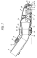
- Fig. 1 is a vertical sectional view showing one embodiment of a suction nozzle with a rotary brush for a vacuum cleaner according to the present invention;
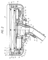
- Fig. 2 is a part arrangement view in which an upper case and a suction port cover of the suction nozzle with a rotary brush are detached;
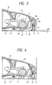
- Fig. 3 is an enlarged sectional view showing an essential portion of a suction nozzle main body having a front side flexible and a suction guide wall;
- Fig. 4 is an essential sectional view in which a suction nozzle main body contacts to the wall etc.,;
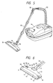
- Fig. 5 is an outside appearance view in which a suction nozzle main body is mounted on a vacuum cleaner main body;
- Fig. 6 is an outside appearance view showing a suction nozzle main body;
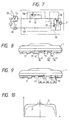
- Fig. 7 is an electric circuit diagram of one embodiment according to the present invention;
- Fig. 8 is a front view showing one embodiment of a suction nozzle main body having a front side flexible member;
- Fig. 9 is a front view showing another embodiment of a suction nozzle main body having another front side flexible member;
- Fig. 10 is static pressure distribution graphs in a suction opening according to the conventional art and the present invention;
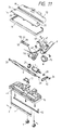
- Fig. 11 is an exploded view showing a suction nozzle main body according to one embodiment of the present invention;
- Fig. 12 is an exploded view showing a bent coupling turning portion of a suction nozzle main body; and
- Fig. 13 is an outside appearance showing a back side of a suction nozzle main body according to one embodiment of the present invention.
- One embodiment of a suction nozzle with a rotary brush for a vacuum cleaner according to the present invention will be explained referring to drawings.
- In a suction nozzle
main body 1 of a suction nozzle with a rotary brush for a vacuum cleaner, anelectric motor 2 and arotary brush 3 are provided at an internal portion thereof. At a bottom face of the suction nozzlemain body 1, a long sidewayssuction opening 4 is formed. The long sideways suction opening 4 opens toward a subjective cleaning surface such as a carpet surface, a tatami mat surface and a floor surface etc.. - At a rear wall portion of the suction nozzle
main body 1, abent coupling 6 is provided so as to turn at the back and forth directions or the right and left directions.
A communicatingpassage 5 for communicating between the suction opening 4 and thebent coupling 6 is formed at the internal portion of the suction nozzlemain body 1. - At the bottom portion of the suction nozzle
main body 1, twolarge size wheels small size wheels - At the vicinity of the
suction opening 4 provided on the bottom surface of the suction nozzlemain body 1, side thin plate shape front sideflexible member 11 and a rear side thin plate shapeflexible member 12 are arranged respectively at the front side and the rear side of the suction opening 4 and extended over the whole lateral width of the suction opening 4 at the horizontal direction. - A lower face of the front wall of the suction nozzle
main body 1 is formed to recede beyond the bottom portion of the suction nozzlemain body 1 and thus the front sideflexible member 11 is mounted detachably atsuch recess position 63. - The suction nozzle
main body 1 comprises anupper case 13 made of synthetic resins material which constitutes an upper surface, a suction port cover 14 made of synthetic resins material, and alower case 15 made of synthetic resins material which constitutes a bottom surface. Thelower case 15 is fitted to theupper case 13 byscrews 16. Thesuction port cover 14 is attached detachably with theupper case 13 and thelower case 15. - Interior components comprise the
electric motor 2, therotary brush 3, anozzle piece 17 provided in the communicatingpassage 5, and acasing 18 which supports rotatively thebent coupling 6 at the back and forth directions, each of the components is installed in the suction nozzlemain body 1, respectively. The interior components are sandwiched and fixed between theupper case 13 and thelower case 15. - A
bumper 19, which is installed so as to surround the outer peripheral portion of thecasing 18, is also sandwiched and fixed between theupper case 13 and thelower case 15. Thebent coupling 6 is supported rotatively with thecasing 18 at the right and left directions, and thecasing 18 is supported rotatively by the suction nozzlemain body 1 at the back and forth directions. Accordingly, thebent coupling 6 can turn with the suction nozzlemain body 1 at the back and forth directions and also at the right and left directions. - The
electric motor 2 is supported in the suction nozzlemain body 1 vibrationally insulated by
two rubbercushion insulator members first pulley 24 having afirst flange portion 23, abearing 25, and abearing cover 26 for receiving the bearing 25 with thelower case 15 are provided at the end portion of arotative shaft 22 of theelectric motor 2. - A
second pulley 27 having asecond flange portion 28 is provided at the end portion of therotary brush 3.
Thefirst pulley 27 and thesecond pulley 27 have same tooth forms and, however, are made to have different tooth numbers. Thefirst flange portion 23 of thefirst pulley 24 is positioned at the side wall portion side of the suction nozzlemain body 1. Thesecond flange portion 28 of thesecond pulley 27 is positioned at thesuction opening 4 side of the suction nozzlemain body 1, which is in the opposite side of thefirst flange portion 23. -
Bearings rotary brush 3 are mounted to both end portions of therotary brush 3. Aprojection member 31 of therotary brush bearing 29 is put into with a bent portion of thesecond pulley 27 and theprojection member 31 and aprojection member 32 are put into the normal position after the press fitting. Therotary brush bearing 29 is supported by the inner side wall portion of the suction nozzlemain body 1. Accordingly therotary brush 3 is supported rotatively with the suction nozzlemain body 1. - A
timing belt 64 is put up between thefirst pulley 24 and thesecond pulley 27, so that the driving power of theelectric motor 2 is transmitted to therotary brush 2. Therotary brush 3 is made of urethane foam material and provides a plurality of spirally formed brushes 33 and a spirally projected beatingprojection member 34. - Two clamps 35 are mounted on at both end portions of the suction port cover 14 of the
rotary brush 3, and therotary brush 3 is formed so as to be taken out together with therotary brush bearings suction port cover 14. Theclamp 35 comprises aclamp portion 37 and aprojection slip member 39. Theclamp portion 37 fits with aprojection member 36 and is disposed detachably so as to fix or remove theprojection member 36. - The
projection member 36 is provided on theupper case 13 which is fixed to the suction nozzlemain body 1. Theprojection slip member 39 is hooked and fixed with a fixingrecess portion 37 which is provided on thelower case 15. Thesuction port cover 14 is disposed detachably by theclamp 35. A bearingpresser bar spring 40 is provided on the suction port cover 14 at the upper portions of therotary brush bearings - At the
lower case 15 side of the front portion of thesuction opening 4 of the suction nozzlemain body 1, the front sideflexible member 11 and asuction guide wall 42 are provided as shown in Fig. 6. The front sideflexible member 11 has a plurality of indented and notched opening grooves or slits 41. Thesuction guide wall 42 is curved and leaned toward thesuction opening 4 side in the suction nozzlemain body 1. The length of the front sideflexible member 11 is set at the lower side longer than the lower end of thesuction guide wall 42. - At the upper end portion side or at a portion near the root side of the front side
flexible member 11, anend portion 19a of thebumper 19 is provided with a contact state. At the rear portion of thesuction opening 4 of the suction nozzlemain body 1, the rear sideflexible member 12 is provided in parallel with a lateral width direction of thesuction opening 4. The height of the rear sideflexible member 12 is set shorter than that of the front sideflexible member 11. - The
suction opening 4 of the suction nozzlemain body 1 communicates with thecasing 18 and thebent coupling 6 through the communicatingpassage 5 in the suction nozzlemain body 1. Thecasing 18 is supported rotatively with therotative shaft 43, and thecasing 18 and thebent coupling 6 are constituted rotatively at the right and left directions, respectively. - Connecting pins 47 are provided on the
bent coupling 6. The connecting pins 47 are connected so as to supply the electric power from the vacuum cleanermain body 44 side to theelectric motor 2 side through ahose 45 and anextension pipe 46. - Lead
wires 48 are wired from the connecting pins 47. Afirst protection cover 49 and asecond protection cover 50 for protecting thelead wires 48 are provided respectively with the covering and enveloping state for thebent coupling 6. A space is formed between thefirst protection cover 49 and thebent coupling 6, thereby thelead wires 48 can move freely according to the movement of thebent coupling 6. - The
first protection cover 49 and thesecond protection cover 50 are constituted as follows. A part of thesecond protection cover 50 is fixed to thebent coupling 6 byscrews 51. Thesecond protection cover 50 has atube shape body 52 and is connected with thecasing 18 side. Thesecond protection cover 50 is overlapped toward thecasing 18 side by a faucetjoint member 53. After thefirst protection cover 49 has been fixed to thetube shape body 52, thefirst protection cover 59 is fixed also to thebent coupling 6 byscrews 54. - The
lead wires 48 supply the electric power according to the wirings of an electric circuit diagram shown in Fig. 7. Three LED (light emitting diode)lamps substrate plate 55, which is arranged in the electric wirings, are arranged to be switched off when therotary brush 3 stops, and to be switched on one by one by aswitch 59 disposed at the tip of thehose 45 in accordance with the rotation of therotary brush 3. The on- or off-state of the threeLED lamps display portion 60 provided on theupper case 13. - With the above stated suction nozzle for a vacuum cleaner structure of the present invention, in case of the cleaning operation, each of the components is connected as shown in Fig. 5 and then the
switch 59 disposed at the tip of thehose 45 is turned at the on condition toward a terminal C₁ side. Then an electric blower 61 of the vacuum cleanermain body 44 side and theelectric motor 2 of the suction nozzlemain body 1 side start to the operation and the LED lamp 56 (green) of thedisplay portion 60 is switched on. With this condition, since therotary brush 3 rotates at a low speed, the cleaning operation is suitable for the thin carpet and the tatami mat etc. - Next, when the
switch 59 is turned on by switching to a terminal C₂ side, theelectric motor 2 in the suction nozzlemain body 1 rotates at a high speed, and also therotary brush 3 can rotate at a high speed similarly. The two LED lamps 56 (green) and 57 (green) are switched on. With this condition, the cleaning operation is suitable for the thick carpet. - The LED lamp 58 (red) includes a positive
characteristic thermistor 62 as shown in an electric circuit diagram of Fig. 7. In case that therotary brush 3 drags in foreign matters etc. and its rotation is blocked by these, thethermistor 62 of the LED lamp 58 (red) presents the exothermic condition and increases the resistance value thereof. Then the current electric current direction of thethermistor 62 of the LED lamp 58 (red) is changed to a direction marked by an arrow R as shown in Fig. 7. The LED lamp 56 (red) is switched on and the operator can notice such an abnormal condition. When the LED lamp 56 (red) is switched on, then the LED lamps 56 (green) and 57 (green) are switched off. - When the
switch 59 is turned to a terminal C₃ side of Fig. 7, the electric power supply to theelectric motor 2 and the electric blower 61 shuts off, and the cleaning operation is stopped. The rotating speed of theelectric motor 2 while theswitch 59 is turned to the terminal C₂ side of Fig. 7 is set about 75 % of the rotating speed of theelectric motor 2 while theswitch 59 is turned to the terminal C₁ side of Fig. 7. - The front side
flexible member 11 and the rear sideflexible member 12, have lengths for contacting to the subjective cleaning surface with the front sideflexible member 11 and the rear sideflexible member 12 as shown in Fig. 1. When a surface of a floor, a tatami mat etc. is to be cleaned with the suction nozzle, the front sideflexible member 11 and the rear sideflexible member 12 are bent respectively by the surface air flow being generated by the vacuum cleanermain body 44 as shown in Fig. 3. - A clearance A between the front side
flexible member 11 or the rear sideflexible member 12 and the subjective cleaning surface due to this bending varies according to the air quantity in the vacuum cleanermain body 44. In case that the air quantity in the vacuum cleanermain body 44 is large, in other words in case of the condition that the filter member in the vacuum cleanermain body 44 is not blocked, the clearance A becomes large. Besides in case that the air quantity in the vacuum cleanermain body 11 is small due to the blocking by the filter member in the vacuum cleanermain body 44, the clearance A becomes small. As stated above, the air flow velocity flowing into thesuction opening 4 of the suction nozzlemain body 1 is made constant by the change of the clearance A. - The set sizes of a plurality of the opening
grooves 41 formed on the front sideflexible member 11 are as follows. In comparison with the pressure distribution of the conventional vacuum cleaner having suction nozzle in which the pressure distribution is high at the central portion and low at both end portions as shown in the curve line P in Fig. 10, in the vacuum cleaner having suction nozzle of the present invention, the pressure distribution is made on average and high throughout the overall lateral width of the suction nozzle as shown in the curve line Q in Fig. 10. - As the set for size of the front side
flexible member 11, one example is that the height of the front sideflexible member 11 is made constant but the widths W₁, W₂, W₃ thereof are set to decrease proportionally toward both end portions of the front sideflexible member 11 as shown in Fig. 8. - As another example of the set of size for the front side
flexible member 11, the width W of the front sideflexible member 11 is made at constant but the heights H₁, H₂, H₃ thereof are set to decrease proportionally toward both end portions of the front sideflexible member 11 as shown in Fig. 9. - By the pressure distribution shown in the curve line Q in Fig. 10, in the present invention, the strong suction force can be generated at the lengthwise direction all over the
suction opening 4 of the suction nozzlemain body 1. - When the operator wishes to clean the carpet etc. by use of the
rotary brush 3, since the front sideflexible member 11 of the suction nozzlemain body 1 is attached to theindented portion 63 which is indented more than the bottom surface of the suction nozzlemain body 1, the operation of the suction nozzlemain body 1 can do easily and smoothly. - For example, even when the front side
flexible member 11 contacts with the down of the carpet, since the front sideflexible member 11 is constituted to lengthen, it is possible to perform easily and smoothly the operation of the suction nozzlemain body 1 because the resistance receiving from the carpet is made small. - The
suction guide wall 42, which is disposed between the front sideflexible member 11 and thesuction opening 4, is arranged slanting toward the inside portion of the suction nozzlemain body 1. Thesuction guide wall 42 does not block the move of the bending of the front sideflexible member 11. - Also the front side
flexible member 11 prevents therotary brush 3 from contacting, due to contact the threshold and push into the front sideflexible member 11 toward the inside portion thereof, by the provision of thesuction guide wall 42. The carpet having long down such as a shaggy type carpet is prevented from twining around therotary brush 3 by the provision of thesuction guide wall 42. - When the
bumper 19 provided on the front surface of the suction nozzlemain body 1 collides with the wall or the furniture in the room, thebumper 19 deforms through pushing by the wall or the furniture. Alower end portion 62 of thebumper 19 and the root portion of the front sideflexible member 11 are pushed respectively toward the inside thereof. - Since the clearance A between the front side
flexible member 11 and the subjective cleaning surface is made large irrespective of the suction air amount, the large size solid dust such as a peanut is not left behind at the corner portion in the room and is sucked smoothly into thesuction opening 4 of the suction nozzlemain body 1. - Further, the front side
flexible member 11 is provided on the axis line of thesmall wheels flexible member 11 and the subjective cleaning surface can be maintained constant. - When the front side
flexible member 11 is bent toward inside portion thereof by the suction force generated at thesuction opening 4 of the suction nozzlemain body 1, the tip of the front sideflexible member 11 covers a part of thesuction opening 4. Therefore, the opening area of thesuction opening 4 is made small and since the suction force is increased, the large size solid dust can be sucked more smoothly into thesuction opening 4 of the suction nozzlemain body 1. - When the front side
flexible member 11 is worn out, since the front sideflexible member 11 is made separately from thebumper 19 and mounted detachably at therecess portion 63 of the front wall of the suction nozzlemain body 1, the front sideflexible member 11 can be changed easily independently from thebumper 19. - Since the front side
flexible member 11 is disposed at therecess portion 63 which is provided further at a position retreated from the bottom surface of the suction nozzlemain body 1, the curve rate for deforming of the front sideflexible member 11 comprising an elastic material can be made small. The life of the front sideflexible member 11 can be lengthened by avoiding the compulsory force at its root portion on bending. Further, the force for operating the suction nozzlemain body 1 in the back and forth direction can be decreased. - The
suction guide wall 42 disposed at the rear side (suction port side) of the front sideflexible member 11 is inclined towards thesuction opening 4 side. Therefore, even when the front sideflexible member 11 collides with the projection portion (the edge portion of the carpet, the step of the threshold etc.) generated at the subjective cleaning surface and is bent inside thereof by pushing, the front sideflexible member 11 can be prevented from colliding with therotary brush 3.
Even when the front sideflexible member 11 receives a compulsory force, thesuction guide wall 42 works as a wall for receiving the compulsory force, thereby the front sideflexible member 11 can be prevented from tearing or being injured. - Further, the shaggy carpet having long down clings easily with the
rotary brush 3. In such a case, thesuction guide wall 42 can prevent the long down from clinging to therotary brush 3 by pushing out the long down of the shaggy carpet. Even when the carpet having the long down is used, the variation of rotation number of therotary brush 3 can be decreased. - The rotation number of the
rotary brush 3 can be selected high or low according to conditions of use. Even on the tatami mat, the cleaning is carried out at a low rotation number of therotary brush 3. Therefore, the cleaning of the tatami mat can be carried out maintaining the sweeping effect and the tatami mat is not injured. - Since the condition of the rotation of the
rotary brush 3 is displayed at the upper portion of the suction nozzlemain body 1, the operator can notice immediately the operating states, in which the floor is injured in the floor cleaning by the rotation of therotary brush 3, or therotary brush 3 catches foreign matters and becomes blocked. Therotary brush 3 can always be used in the normal rotation condition. - The
rotary brush bearings rotary brush 3 are held at the set pressure force with a pre-determined constant direction. Even when an unbalance is generated in therotary brush 3, the vibration noise in therotary brush 3 caused by the above unbalance can be restrained. - Since the
second flange portion 28 provided on thesecond pulley 27 of therotary brush 3 is mounted toward the inside direction thereof, even in case that therotary brush 3 is detached, thetiming belt 64 is not hooked by thesecond flange portion 28 and can be detached smoothly when servicing the suction nozzlemain body 1. - Further, since the power source line which projects from the
bent coupling 6 toward the outside portion is enclosed therein, the power source line does not hang to the lower portion of the disk or the leg of the furniture. Therefore, it is possible to clean the cleaning surface in a low and narrow place and the safety for the power surface line can be increased without exerting a compulsive outside force at the root portion of the power source line. - Further, the
bent coupling 6 turning portion of the suction nozzlemain body 1 in the present invention is formed with the following structure. The shapes of the protection covers constituting the outside shell for thebent coupling 6 are formed to be engaged with thecylinder faucet portion 53 at thecasing 18 side and are put the upper and lower fitting structure together at thebent coupling 6 side. Even when a large outside force is exerted at thebent coupling 6 turning portion, the engagement portion thereof does not open, and further the fitting portion thereof does not slip out of place. - Further, since the
internal lead wires 48 are arranged with a free shape and with no compulsive force at the space which is formed between thefirst protection cover 49 and thebent coupling 6, theinternal lead wires 48 can move freely when movements in the upper and lower directions and the right and left directions act on them, so that the folding life of theinternal lead wires 48 can be improved widely.
Claims (1)
- A suction nozzle with a rotary brush for a vacuum cleaner comprising a suction nozzle main body (1) being formed with a long sideways suction opening (4) which opens towards a floor surface, a rotary brush (3) rotatably arranged facing said suction opening (4), an electric motor (2) for driving said rotary brush (3), a casing (18) provided at a central portion of a rear portion of said suction nozzle main body (1), connected to said main body (1) rotatably in the up and down directions and having a suction passage formed in it, a turnable bent coupling (6) connected to said casing (18) rotatably in the right and left directions, a protection cover (49, 50) which is disposed on an outside of said turnable bent coupling (6) and defines a space with said turnable bent coupling (6), and an electric power supply wiring (48) which is led to said electric motor (2) of said rotary brush (3) from a vacuum cleaner main body along a hose (45) and an extension pipe (46) and is led into said suction nozzle main body (1) from a side of said casing (18) by passing through the space between said turnable bent coupling (6) and said protection cover (49, 50), further said electric power supply wiring (48) is arranged slackly in said space so as to move freely in the up and down, right and left directions relatively to said turnable bent coupling (6).
Applications Claiming Priority (7)
| Application Number | Priority Date | Filing Date | Title |
|---|---|---|---|
| JP9779288 | 1988-04-20 | ||
| JP63095578A JPH01268526A (en) | 1988-04-20 | 1988-04-20 | Suction port for rotary brush of vacuum cleaner |
| JP95578/88 | 1988-04-20 | ||
| JP97792/88 | 1988-04-20 | ||
| JP9557888 | 1988-04-20 | ||
| JP63097792A JP2514688B2 (en) | 1988-04-20 | 1988-04-20 | Electric vacuum cleaner |
| EP89106940A EP0338513B1 (en) | 1988-04-20 | 1989-04-18 | Suction nozzle with rotary brush for vacuum cleaner |
Related Parent Applications (2)
| Application Number | Title | Priority Date | Filing Date |
|---|---|---|---|
| EP89106940A Division EP0338513B1 (en) | 1988-04-20 | 1989-04-18 | Suction nozzle with rotary brush for vacuum cleaner |
| EP89106940.3 Division | 1989-04-18 |
Publications (4)
| Publication Number | Publication Date |
|---|---|
| EP0590690A2 true EP0590690A2 (en) | 1994-04-06 |
| EP0590690A3 EP0590690A3 (en) | 1994-05-18 |
| EP0590690B1 EP0590690B1 (en) | 1996-11-27 |
| EP0590690B2 EP0590690B2 (en) | 2001-12-05 |
Family
ID=26436791
Family Applications (2)
| Application Number | Title | Priority Date | Filing Date |
|---|---|---|---|
| EP93116250A Expired - Lifetime EP0590690B2 (en) | 1988-04-20 | 1989-04-18 | Suction nozzle |
| EP89106940A Expired - Lifetime EP0338513B1 (en) | 1988-04-20 | 1989-04-18 | Suction nozzle with rotary brush for vacuum cleaner |
Family Applications After (1)
| Application Number | Title | Priority Date | Filing Date |
|---|---|---|---|
| EP89106940A Expired - Lifetime EP0338513B1 (en) | 1988-04-20 | 1989-04-18 | Suction nozzle with rotary brush for vacuum cleaner |
Country Status (5)
| Country | Link |
|---|---|
| US (1) | US5054156A (en) |
| EP (2) | EP0590690B2 (en) |
| KR (1) | KR960014808B1 (en) |
| CN (1) | CN1016136B (en) |
| DE (2) | DE68916578T2 (en) |
Cited By (5)
| Publication number | Priority date | Publication date | Assignee | Title |
|---|---|---|---|---|
| DE29611160U1 (en) * | 1996-06-26 | 1996-08-29 | Wessel-Werk GmbH, 51580 Reichshof | Suction head on a vacuum cleaner |
| EP0909547A3 (en) * | 1997-10-14 | 1999-07-28 | Oreck Holdings, LLC | Vacuum cleaner having top access brush panel |
| EP1138243A3 (en) * | 2000-03-28 | 2003-07-09 | Samsung Kwangju Electronics Co., Ltd. | Vacuum cleaner apparatus |
| US6842941B2 (en) | 2000-10-31 | 2005-01-18 | Samsung Kwangju Electronics Co., Ltd. | Suction port assembly of vacuum cleaner |
| WO2009066050A1 (en) * | 2007-11-23 | 2009-05-28 | Dyson Technology Limited | A surface treating appliance |
Families Citing this family (31)
| Publication number | Priority date | Publication date | Assignee | Title |
|---|---|---|---|---|
| US5291628A (en) * | 1991-12-12 | 1994-03-08 | Xerox Corporation | High velocity air cleaner |
| US5280666A (en) * | 1992-05-19 | 1994-01-25 | Rexair, Inc. | Squeegee apparatus for a vacuum cleaner system |
| US5309601A (en) * | 1992-10-16 | 1994-05-10 | White Consolidated Industries, Inc. | Vacuum cleaner with improved assembly |
| US5389004A (en) * | 1993-04-23 | 1995-02-14 | Electrolux Corporation | Handle and wand system for vacuum cleaner |
| DE4403971B4 (en) * | 1993-06-25 | 2007-03-01 | Vorwerk & Co. Interholding Gmbh | Floor suction device, in particular intent or part of an electric vacuum cleaner |
| US5537710A (en) * | 1993-11-02 | 1996-07-23 | Rexair, Inc. | Cleaning tool having split manifold |
| DE4420892A1 (en) * | 1994-06-15 | 1995-12-21 | Aeg Hausgeraete Gmbh | Suction mouthpiece for vacuum cleaners |
| DE4424809A1 (en) | 1994-07-14 | 1996-01-18 | Licentia Gmbh | Suction mouthpiece with sealing strip |
| US6029313A (en) * | 1996-11-15 | 2000-02-29 | Black & Decker, Inc. | Vacuum cleaner with cantilevered drive system and removable belt access door |
| GB2317817B (en) * | 1997-01-30 | 1998-12-02 | Notetry Ltd | Vacuum cleaner |
| US6226832B1 (en) | 1998-04-23 | 2001-05-08 | Matsushita Home Appliance Corporation Of America | Easy maintenance vacuum cleaner |
| US7159277B2 (en) * | 2001-02-06 | 2007-01-09 | The Hoover Company | Multiple chamber suction nozzle configuration |
| KR100574308B1 (en) * | 2002-12-27 | 2006-04-27 | 샤프 가부시키가이샤 | Suction head for electric cleaner and electric cleaner having the same |
| WO2006015309A2 (en) | 2004-07-29 | 2006-02-09 | Electrolux Care Products, Ltd | Upright vacuum cleaner |
| GB0422907D0 (en) * | 2004-10-15 | 2004-11-17 | Dyson Technology Ltd | A vacuum cleaning head |
| US7631387B2 (en) * | 2005-05-13 | 2009-12-15 | Black & Decker Inc. | Motorized broom and collector |
| USD548911S1 (en) | 2005-05-13 | 2007-08-14 | Black & Decker Inc. | Combined motorized broom and collector |
| US9903371B2 (en) * | 2008-09-17 | 2018-02-27 | Resmed Limited | Cuff for air delivery conduit |
| USD742508S1 (en) | 2013-07-12 | 2015-11-03 | Resmed Limited | Air delivery tube with cuff |
| DE102009048053A1 (en) | 2009-10-02 | 2011-05-05 | Wessel-Werk Gmbh | Brush attachment for vacuum cleaners |
| DE102010038026A1 (en) | 2010-10-06 | 2012-04-12 | Düpro AG | Vacuum cleaner nozzle with magnetic lock |
| KR101573742B1 (en) * | 2010-10-25 | 2015-12-07 | 삼성전자주식회사 | Autonomous cleaning device |
| AU2011254078B2 (en) | 2010-12-29 | 2014-05-22 | Bissell Inc. | Suction nozzle with obstacle sensor |
| CN102648837A (en) * | 2011-02-24 | 2012-08-29 | 苏州韩京姬科技有限公司 | Base assembly for floor cleaner |
| CN102551618A (en) * | 2012-02-08 | 2012-07-11 | 张关池 | Simple dish-washing machine |
| USD762843S1 (en) | 2014-03-18 | 2016-08-02 | Resmed Limited | Air delivery tube |
| DE102014114375A1 (en) * | 2014-10-02 | 2016-04-07 | Vorwerk & Co. Interholding Gmbh | Powered brush as attachment for a vacuum cleaner |
| US10375901B2 (en) | 2014-12-09 | 2019-08-13 | Mtd Products Inc | Blower/vacuum |
| USD805630S1 (en) | 2016-02-02 | 2017-12-19 | Resmed Limited | Air delivery tube |
| GB2554937B (en) * | 2016-10-14 | 2020-03-11 | Tti Macao Commercial Offshore Ltd | A tool for a surface cleaning apparatus |
| KR20220062967A (en) * | 2020-11-09 | 2022-05-17 | 삼성전자주식회사 | A vaccum cleaner |
Family Cites Families (18)
| Publication number | Priority date | Publication date | Assignee | Title |
|---|---|---|---|---|
| US2324111A (en) * | 1941-02-25 | 1943-07-13 | Electrolux Corp | Suction nozzle with automatically retractable surface-contacting element |
| US2717409A (en) * | 1950-09-15 | 1955-09-13 | Herbert T Draudt | Vacuum cleaner nozzle |
| US2846711A (en) * | 1953-09-17 | 1958-08-12 | Hoover Co | Nap flicker type suction cleaning nozzle |
| NL107127C (en) * | 1957-06-28 | |||
| US3019462A (en) * | 1960-01-26 | 1962-02-06 | Jacuzzi Bros Inc | Vacuum cleaner |
| FR1434865A (en) * | 1964-05-28 | 1966-04-08 | Electrolux Ab | Dust extraction device |
| JPS6038127B2 (en) * | 1973-03-28 | 1985-08-30 | 株式会社日立製作所 | vacuum cleaner suction port |
| JPS52112159A (en) * | 1976-03-17 | 1977-09-20 | Toshiba Corp | Heat exchanger |
| DE7628311U1 (en) * | 1976-09-10 | 1977-01-27 | Vorwerk & Co Elektrowerke Gmbh & Co Kg, 5600 Wuppertal | VACUUM MOUTH PIECE |
| DE2737013C2 (en) * | 1977-08-17 | 1985-02-21 | Vorwerk & Co Interholding Gmbh, 5600 Wuppertal | Connection piece for electromotive operated attachment nozzles for floor care devices |
| CA1115465A (en) * | 1978-01-19 | 1982-01-05 | Ryuichi Yasunaga | Vacuum cleaner |
| JPS55120824A (en) * | 1979-03-12 | 1980-09-17 | Hitachi Ltd | Suction port for rotary brush of vacuum cleaner |
| JPS55130633A (en) * | 1979-04-02 | 1980-10-09 | Hitachi Ltd | Rotary brush suction port of electric cleaner |
| DE3041881A1 (en) * | 1980-11-06 | 1982-06-09 | Vorwerk & Co Interholding Gmbh, 5600 Wuppertal | DEVICE FOR FRONT SUCTION ON VACUUM CLEANERS |
| US4499628A (en) * | 1983-06-09 | 1985-02-19 | Whirlpool Corporation | Vacuum cleaning apparatus |
| DE8437619U1 (en) * | 1984-12-21 | 1986-04-17 | Siemens AG, 1000 Berlin und 8000 München | Brush suction nozzle with impellers |
| US4817233A (en) * | 1988-04-22 | 1989-04-04 | Tennant Company | Scrubber squeegees for scrubbing forward and backward |
| DE3904395A1 (en) * | 1989-02-14 | 1990-08-16 | Mauz & Pfeiffer Progress | Suction connection-piece for a vacuum cleaner |
-
1989
- 1989-04-17 US US07/338,859 patent/US5054156A/en not_active Expired - Fee Related
- 1989-04-18 EP EP93116250A patent/EP0590690B2/en not_active Expired - Lifetime
- 1989-04-18 DE DE68916578T patent/DE68916578T2/en not_active Expired - Lifetime
- 1989-04-18 EP EP89106940A patent/EP0338513B1/en not_active Expired - Lifetime
- 1989-04-18 DE DE68927501T patent/DE68927501T3/en not_active Expired - Lifetime
- 1989-04-19 CN CN89102567A patent/CN1016136B/en not_active Expired
- 1989-04-20 KR KR1019890005209A patent/KR960014808B1/en not_active Expired - Lifetime
Cited By (7)
| Publication number | Priority date | Publication date | Assignee | Title |
|---|---|---|---|---|
| DE29611160U1 (en) * | 1996-06-26 | 1996-08-29 | Wessel-Werk GmbH, 51580 Reichshof | Suction head on a vacuum cleaner |
| EP0909547A3 (en) * | 1997-10-14 | 1999-07-28 | Oreck Holdings, LLC | Vacuum cleaner having top access brush panel |
| EP1138243A3 (en) * | 2000-03-28 | 2003-07-09 | Samsung Kwangju Electronics Co., Ltd. | Vacuum cleaner apparatus |
| US6792648B2 (en) | 2000-03-28 | 2004-09-21 | Samsung Kwangju Electronics Co., Ltd. | Floor cloth for use in vacuum cleaner and apparatus of vacuum cleaner for rotatably driving the floor cloth |
| US6842941B2 (en) | 2000-10-31 | 2005-01-18 | Samsung Kwangju Electronics Co., Ltd. | Suction port assembly of vacuum cleaner |
| WO2009066050A1 (en) * | 2007-11-23 | 2009-05-28 | Dyson Technology Limited | A surface treating appliance |
| US8347454B2 (en) | 2007-11-23 | 2013-01-08 | Dyson Technology Limited | Swivel electrical connector for a suction head of a surface treating appliance |
Also Published As
| Publication number | Publication date |
|---|---|
| EP0590690A3 (en) | 1994-05-18 |
| DE68927501T2 (en) | 1997-03-27 |
| EP0338513B1 (en) | 1994-07-06 |
| DE68916578T2 (en) | 1994-10-20 |
| KR900015678A (en) | 1990-11-10 |
| CN1016136B (en) | 1992-04-08 |
| EP0338513A2 (en) | 1989-10-25 |
| EP0338513A3 (en) | 1991-07-31 |
| DE68927501T3 (en) | 2002-04-11 |
| CN1037829A (en) | 1989-12-13 |
| EP0590690B1 (en) | 1996-11-27 |
| KR960014808B1 (en) | 1996-10-21 |
| DE68927501D1 (en) | 1997-01-09 |
| DE68916578D1 (en) | 1994-08-11 |
| EP0590690B2 (en) | 2001-12-05 |
| US5054156A (en) | 1991-10-08 |
Similar Documents
| Publication | Publication Date | Title |
|---|---|---|
| EP0338513B1 (en) | Suction nozzle with rotary brush for vacuum cleaner | |
| US5101534A (en) | Suction nozzle with rotary brush for vacuum cleaner | |
| US4893376A (en) | Upright-type electric vacuum cleaner | |
| US5297312A (en) | Cleaning appliance with agitation member mounting bracket | |
| US5398373A (en) | Combination vacuum cleaner and water extractor power foot | |
| US2128525A (en) | Vacuum cleaner | |
| JPH0910143A (en) | Vacuum cleaner suction body | |
| US4109342A (en) | Vacuum cleaner with bare floor cleaning brush | |
| US2517670A (en) | Converter attachment for suction cleaners | |
| JP3187346B2 (en) | Suction body for vacuum cleaner and vacuum cleaner using the same | |
| CN216984726U (en) | A remove mite head and cleaning machine for cleaning machine | |
| CN114680709B (en) | Mite removing head for cleaning machine and cleaning machine | |
| JPH01268526A (en) | Suction port for rotary brush of vacuum cleaner | |
| KR100306267B1 (en) | Suction Instrument For Using Onto A Floor | |
| KR960014809B1 (en) | Electric vacuum cleaner | |
| JPH1147051A (en) | Suction body for vacuum cleaner and vacuum cleaner using the same | |
| CN1061711A (en) | Suction head with rotating brush for vacuum cleaner | |
| JP4011058B2 (en) | Floor suction tool | |
| KR200364055Y1 (en) | A suction nozzle for vacuum cleaner | |
| JP3594174B2 (en) | Vacuum cleaner and its suction body | |
| JP3819565B2 (en) | Floor suction tool | |
| JP2514688B2 (en) | Electric vacuum cleaner | |
| KR200144822Y1 (en) | Wheel rotating device using exhaust air of vacuum cleaner | |
| JPH07204137A (en) | Vacuum cleaner mouthpiece | |
| US1541567A (en) | Electric suction cleaner |
Legal Events
| Date | Code | Title | Description |
|---|---|---|---|
| PUAI | Public reference made under article 153(3) epc to a published international application that has entered the european phase |
Free format text: ORIGINAL CODE: 0009012 |
|
| PUAL | Search report despatched |
Free format text: ORIGINAL CODE: 0009013 |
|
| AC | Divisional application: reference to earlier application |
Ref document number: 338513 Country of ref document: EP |
|
| AK | Designated contracting states |
Kind code of ref document: A2 Designated state(s): DE GB |
|
| AK | Designated contracting states |
Kind code of ref document: A3 Designated state(s): DE GB |
|
| 17P | Request for examination filed |
Effective date: 19940325 |
|
| 17Q | First examination report despatched |
Effective date: 19950801 |
|
| GRAG | Despatch of communication of intention to grant |
Free format text: ORIGINAL CODE: EPIDOS AGRA |
|
| GRAH | Despatch of communication of intention to grant a patent |
Free format text: ORIGINAL CODE: EPIDOS IGRA |
|
| GRAH | Despatch of communication of intention to grant a patent |
Free format text: ORIGINAL CODE: EPIDOS IGRA |
|
| GRAA | (expected) grant |
Free format text: ORIGINAL CODE: 0009210 |
|
| AC | Divisional application: reference to earlier application |
Ref document number: 338513 Country of ref document: EP |
|
| AK | Designated contracting states |
Kind code of ref document: B1 Designated state(s): DE GB |
|
| REF | Corresponds to: |
Ref document number: 68927501 Country of ref document: DE Date of ref document: 19970109 |
|
| PLBQ | Unpublished change to opponent data |
Free format text: ORIGINAL CODE: EPIDOS OPPO |
|
| PLBI | Opposition filed |
Free format text: ORIGINAL CODE: 0009260 |
|
| PLBF | Reply of patent proprietor to notice(s) of opposition |
Free format text: ORIGINAL CODE: EPIDOS OBSO |
|
| 26 | Opposition filed |
Opponent name: WESSEL-WERK GMBH Effective date: 19970826 |
|
| PLBF | Reply of patent proprietor to notice(s) of opposition |
Free format text: ORIGINAL CODE: EPIDOS OBSO |
|
| PLAW | Interlocutory decision in opposition |
Free format text: ORIGINAL CODE: EPIDOS IDOP |
|
| APAC | Appeal dossier modified |
Free format text: ORIGINAL CODE: EPIDOS NOAPO |
|
| APAE | Appeal reference modified |
Free format text: ORIGINAL CODE: EPIDOS REFNO |
|
| APAC | Appeal dossier modified |
Free format text: ORIGINAL CODE: EPIDOS NOAPO |
|
| APAC | Appeal dossier modified |
Free format text: ORIGINAL CODE: EPIDOS NOAPO |
|
| PLAW | Interlocutory decision in opposition |
Free format text: ORIGINAL CODE: EPIDOS IDOP |
|
| PUAH | Patent maintained in amended form |
Free format text: ORIGINAL CODE: 0009272 |
|
| STAA | Information on the status of an ep patent application or granted ep patent |
Free format text: STATUS: PATENT MAINTAINED AS AMENDED |
|
| 27A | Patent maintained in amended form |
Effective date: 20011205 |
|
| AK | Designated contracting states |
Kind code of ref document: B2 Designated state(s): DE GB |
|
| REG | Reference to a national code |
Ref country code: GB Ref legal event code: IF02 |
|
| EN | Fr: translation not filed | ||
| APAH | Appeal reference modified |
Free format text: ORIGINAL CODE: EPIDOSCREFNO |
|
| PGFP | Annual fee paid to national office [announced via postgrant information from national office to epo] |
Ref country code: GB Payment date: 20080328 Year of fee payment: 20 |
|
| PGFP | Annual fee paid to national office [announced via postgrant information from national office to epo] |
Ref country code: DE Payment date: 20080606 Year of fee payment: 20 |
|
| REG | Reference to a national code |
Ref country code: GB Ref legal event code: PE20 Expiry date: 20090417 |
|
| PG25 | Lapsed in a contracting state [announced via postgrant information from national office to epo] |
Ref country code: GB Free format text: LAPSE BECAUSE OF EXPIRATION OF PROTECTION Effective date: 20090417 |