EP0590734A2 - Gerät und Methode zur Fehlerdetektion magnetisch permeabler Teile - Google Patents
Gerät und Methode zur Fehlerdetektion magnetisch permeabler Teile Download PDFInfo
- Publication number
- EP0590734A2 EP0590734A2 EP93202794A EP93202794A EP0590734A2 EP 0590734 A2 EP0590734 A2 EP 0590734A2 EP 93202794 A EP93202794 A EP 93202794A EP 93202794 A EP93202794 A EP 93202794A EP 0590734 A2 EP0590734 A2 EP 0590734A2
- Authority
- EP
- European Patent Office
- Prior art keywords
- field
- sensing
- magnetic
- sensors
- portions
- Prior art date
- Legal status (The legal status is an assumption and is not a legal conclusion. Google has not performed a legal analysis and makes no representation as to the accuracy of the status listed.)
- Withdrawn
Links
Images
Classifications
-
- G—PHYSICS
- G01—MEASURING; TESTING
- G01N—INVESTIGATING OR ANALYSING MATERIALS BY DETERMINING THEIR CHEMICAL OR PHYSICAL PROPERTIES
- G01N27/00—Investigating or analysing materials by the use of electric, electrochemical, or magnetic means
- G01N27/72—Investigating or analysing materials by the use of electric, electrochemical, or magnetic means by investigating magnetic variables
- G01N27/82—Investigating or analysing materials by the use of electric, electrochemical, or magnetic means by investigating magnetic variables for investigating the presence of flaws
-
- B—PERFORMING OPERATIONS; TRANSPORTING
- B65—CONVEYING; PACKING; STORING; HANDLING THIN OR FILAMENTARY MATERIAL
- B65G—TRANSPORT OR STORAGE DEVICES, e.g. CONVEYORS FOR LOADING OR TIPPING, SHOP CONVEYOR SYSTEMS OR PNEUMATIC TUBE CONVEYORS
- B65G43/00—Control devices, e.g. for safety, warning or fault-correcting
- B65G43/02—Control devices, e.g. for safety, warning or fault-correcting detecting dangerous physical condition of load carriers, e.g. for interrupting the drive in the event of overheating
-
- G—PHYSICS
- G01—MEASURING; TESTING
- G01N—INVESTIGATING OR ANALYSING MATERIALS BY DETERMINING THEIR CHEMICAL OR PHYSICAL PROPERTIES
- G01N27/00—Investigating or analysing materials by the use of electric, electrochemical, or magnetic means
- G01N27/72—Investigating or analysing materials by the use of electric, electrochemical, or magnetic means by investigating magnetic variables
- G01N27/82—Investigating or analysing materials by the use of electric, electrochemical, or magnetic means by investigating magnetic variables for investigating the presence of flaws
- G01N27/90—Investigating or analysing materials by the use of electric, electrochemical, or magnetic means by investigating magnetic variables for investigating the presence of flaws using eddy currents
- G01N27/9013—Arrangements for scanning
- G01N27/9026—Arrangements for scanning by moving the material
-
- B—PERFORMING OPERATIONS; TRANSPORTING
- B65—CONVEYING; PACKING; STORING; HANDLING THIN OR FILAMENTARY MATERIAL
- B65G—TRANSPORT OR STORAGE DEVICES, e.g. CONVEYORS FOR LOADING OR TIPPING, SHOP CONVEYOR SYSTEMS OR PNEUMATIC TUBE CONVEYORS
- B65G15/00—Conveyors having endless load-conveying surfaces, i.e. belts and like continuous members, to which tractive effort is transmitted by means other than endless driving elements of similar configuration
- B65G15/30—Belts or like endless load-carriers
- B65G15/32—Belts or like endless load-carriers made of rubber or plastics
- B65G15/34—Belts or like endless load-carriers made of rubber or plastics with reinforcing layers, e.g. of fabric
- B65G15/36—Belts or like endless load-carriers made of rubber or plastics with reinforcing layers, e.g. of fabric the layers incorporating ropes, chains, or rolled steel sections
Definitions
- the present invention relates to electromagnetic sensing and analysis of damage and/or deterioration of objects made of, or incorporating, a magnetically permeable material, and also to an apparatus and method for the analysis of data related to the same, and more particularly to such an apparatus and method which is particularly adapted to perform such sensing and analysis in an article such as an elongate conveyor belt, where reinforcing cables made of the magnetically permeable material are embedded in (and thus largely concealed in) a relatively non-permeable material such as the rubber like structure of the belt.
- conveyor belts are used in a variety of applications, one of the major applications being in the mining industry where metal ore or other material is carried from the mine to a collecting location.
- a conveyor belt extending from a lower location upwardly for a distance as long as several thousand feet or even several miles.
- Such belts can possibly be as large as eight feet wide, and possibly as thick as four inches.
- the main belt material generally is a moderately flexible rubber-like material, and the belt is reinforced by a plurality of longitudinally extending metal cables which are positioned within the belt and extend along the length thereof.
- One of the problems is that after continued use the metal reinforcing cables will deteriorate. For example, there may be a break in the conveyor belt material that would permit water or possibly even an acid (e.g. resulting from water reacting with the conveyed material) to come in contact with one or more of the cables to corrode the cables.
- the damage to the cables could come from an impact of some sort, or the deterioration could occur from natural wear or possibly fatigue of the metal because of long continued use.
- the damage to the cable is a total break, and in some instances a partial deterioration that simply weakens the belt.
- the apparatus of the present invention is arranged to detect anomalies in a magnetically permeable member having a longitudinal axis, by providing a magnetic field at an operating area at which the magnetically permeable member is located.
- the apparatus is arranged relative to said member so that there can be movement of said member relative to said apparatus along the longitudinal axis.
- the apparatus comprises coil means to generate the magnetic field as longitudinally spaced first and second field components at longitudinally spaced first and second locations at the operating area.
- sensing means arranged to respond to modifications in each of the first and second field components.
- the sensing means responds to modifications created by the anomaly in the first and second field components to detect the anomaly.
- the sensing means is arranged to respond to intensity of the magnetic field at a sensing location.
- the sensing means is positioned between the field components so that the sensing location is between said field components.
- the field coil means is arranged to provide at least portions of the first and second field components both extending through the sensing locations.
- the sensing means is arranged to respond to shifts in balance between the first and second field components at the sensing location. More specifically, the coil means is arranged to provide first and second magnetic field loops which have adjacent portions thereof oriented oppositely to one another at the sensing location.
- the field coil means is arranged so that when there is substantially equal magnetic reluctance at the first and second field locations, the first and second field components substantially balance each other at the sensing area.
- the first and second field components vary in strength to create net magnetic field portion at the sensing area.
- the armature means comprises three longitudinally spaced armature portions, namely a forward armature portion, a rear armature portion and an intermediate armature portion between the forward and rear armature portions.
- the coil means further comprises field coil generating means arranged to create the first field component as a magnetic loop extending through the forward armature portion and the intermediate armature portion, and to create the second field component as a second magnetic loop extending through the rear field component and through the intermediate armature portions. Portions of the forward and rear magnetic loops passing into said central armature portion are directed oppositely to one another.
- the sensing means comprises a plurality of magnetic responsive sensors spaced from one another transversely to the longitudinal axis to extend transversely across the operating area.
- the sensors are positioned at a lower edge portion of the intermediate armature portion.
- the sensors can be positioned at a location between upper and lower parts of the intermediate armature portion.
- Alternating current power means is utilized to impose an alternating current on said field coil means to create said first and second field components as alternating magnetic fields.
- the apparatus further comprises circuit means having receiving means to create a processing signal in response to an input from each of the sensors.
- the circuit further comprises multiplexing means to respond to each of said processing signals to create a plurality of multiplexer signal outputs corresponding to processing signals from the sensors.
- processing means to receive the multiplexer signal outputs to identify anomalies associated with certain of said sensors.
- the circuit means comprises field coil frequency control means responsive to linear speed of the member, relative to spacing of said first and second field components. This is done in a manner to relate frequency of the alternating field of said coil means to a time interval of one portion of the member moving, relative to said apparatus, from the first field location to the second field location.
- the apparatus comprises first and second longitudinally spaced sensing means portions positioned at, respectively, the first and second field locations, respectively. Each of the first and second sensing portions is responsive to modifications in the first and second field components, respectively.
- the field coil means is arranged so that when there is substantially equal magnetic reluctance at the first and second field locations, the first and second field components are of substantially equal intensity, and when the magnetic reluctance at the first and second field locations is different, the first and second field components vary in strength.
- the magnetic field intensity at the sensing location is modified to cause said sensing means to respond.
- an armature means comprising three armature sections, as described above, and the first and second sensing portions are positioned between the forward armature portion and the intermediate armature portion and between the rear armature and intermediate armature portion, respectively.
- alternating current power means is utilized to impose an alternating current on said coil means to create the first and second field components as alternating magnetic fields.
- an apparatus is utilized as described above.
- the magnetically permeable member is moved through the operating area to modify reluctance in the first and second components, with this being sensed by the sensing means.
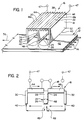
- a portion of a conveyor belt 10 having a main body portion 12 made of a rubber-like moderately resilient material that has relatively low magnetic permeability.
- Embedded in the interior of the main body portion 12 is a plurality of elongate longitudinally extending cables 14 which are spaced laterally from one another along substantially the entire width of the belt.
- a belt having a width of between 12 to 96 inches and a vertical thickness dimension of between about 1/2 to 4 inches there could be as many as 20 to 240 cables, spaced from one another at intervals from about 0.45 to 1.0 inch (measured center line to center line).
- the diameter of such cables could be, in a typical belt, from as large as 1/2 inch.
- the apparatus of the present invention is generally designated 16, and it comprises a "W" shaped yoke 18, two field coils 20 and 22, respectively, wound around two portions 18a and 18b, respectively, of the yoke 18, and one set 24 of Hall effect sensors 26 positioned adjacent to the lower middle portion 28 of the yoke 18.
- the yoke 18 is positioned immediately above the belt 10 and extends transversely across the entire width of the belt 10.
- the yoke 18 comprises three vertically aligned sections, namely forward and rear sections 30 and 32, respectively, and a middle section 34.
- forward and rear sections 30 and 32 respectively
- middle section 34 a section in which the upper run of the belt 10 is moving.
- the yoke 18 comprises a top horizontally aligned section 38 that is connected to (or made integrally with) the three vertically aligned sections 30-34.
- the lower edges 40 of the front and rear vertical sections 30 and 32 are spaced a short distance above (or possibly below the lower surface) the top surface 42 of the belt 10 (e.g. 1/4 to 2 inches above).
- the yoke 18 was desirably made as a plurality of "W" shaped laminations (possibly 1/4 of an inch in thickness) so as to reduce eddy currents in the yoke 18.
- the two field coils 20 and 22 are wound around the forward and rear portions 44 and 46 of the top armature section 38, and these coils 20 and 22 are connected at 47 to a source of alternating current.
- the field coils 20 and 22 generate two alternating magnetic fields one of which extends in a loop from the forward section 30, through the front top yoke portion 44, through the middle yoke section 34 and thence through the portions of the cables 14 which are positioned between the yoke sections 30 and 34.
- the other alternating magnetic field extends through the rear section 34, through the adjacent portion 46 of the top yoke section, through the middle yoke section 34 and thence through the portions of the cables 14 that extend between the yoke sections 32 and 34.
- the Hall effect sensors 26 extend in a transverse row at evenly spaced intervals across the width of the belt 10 and are spaced a short distance (typically between 1/4 to 2 inch above the top surface 42 of the belt 10.
- the sensors 26 are positioned adjacent to, and immediately below the lower edge 48 of the middle section 34 of the yoke 18, and typically, these sensors 26 could be spaced laterally from one another about 1/4 to 1/2 inch (measured center line to center line).
- Each Hall effect sensor 28 is aligned so that its active (i.e. magnetic flux sensing) axis will maximally intersect lines of flux extending upwardly into or downwardly from the lower edge 48 of the middle vertical section 34 above the yoke 18.
- the lower edge 48 of the middle yoke section 34 is located a short distance higher then the lower edges 40 of the front and rear sections 30 and 32.
- the set 24 of the Hall effect sensors 26 is mounted in some suitable manner, either directly to the armature 18 or possibly to some other mounting means.
- the sensors 26 could be mounted to a related printed circuit board which may contain ancillary electronics.
- the supporting structure would support the entire armature 18, coils 20 and 22 and the sensor set 24 in a firm and rigid position that is in static proximity to the upper surface of the belt. For ease of illustration, the particular mounting device is not shown.
- the magnetic field would extend through the two top sections 44 and 46, downwardly through the rear yoke section 32, then across the rear air gap to pass through the portions of the cords 14 that are beneath the yoke 18, thence upwardly through the forward air gap through the forward yoke section 30 to essentially close the loop.
- the two arrows indicated at 49 that would extend upwardly to or downwardly from the center yoke section 34 essentially do not exist. Also, there will be a rather small portion of the magnetic field which extends through the empty space immediately above the belt 10 and extending between the three yoke sections 30, 34 and 32, but this would be negligible.
- the main portions of the cables 14 that are positioned rearwardly and forwardly of the middle section 34 of the yoke 18 would have substantially the same reluctance. Accordingly, the two magnetic loops would be balanced, and at that time the magnetic flux in the middle section 34 would effectively be zero, and the Hall effect sensor or sensors 26 would detect substantially no magnetic field.
- the anomaly in the cable or cables 14 would, as the belt 10 continues to travel forwardly, pass beneath the forward portion of the yoke 18, and the reluctance of the forward magnetic loop would decrease. This would again imbalance the two magnetic loops, with the rear magnetic loop being stronger, and this would in turn create magnetic lines of flux passing either upwardly or downwardly through the Hall effect sensor or sensors 26 in the area adjacent to the anomaly.
- the signal or signals generated by the Hall effect sensor or sensors 26 create a "fingerprint" that would correspond to the nature of the anomaly. For example, if the anomaly is a sharp break in one or more of the cables, this would be expected to create a signal of possibly a shorter duration and having a distinctive shape. On the other hand, if the anomaly is corrosion that extends over a longer length of the cables 14 and the belt 10, then the anomaly would have a different fingerprint related to that anomaly.
- One or more Hall effect sensors would be positioned adjacent to the belt 10, and these would be positioned and aligned so that they would respond to the fluctuating magnetic field created by the coils 20 and 22, somewhat in the manner disclosed in the second embodiment .
- the air gaps would increase or decrease, thus changing the amplitude of the magnetic field sensed by these particular Hall effect sensors.
- the major length of the cables 14 of the conveyor belt 10 would be intact, and thus establish a "signature” that would represent a "healthy” portion of the belt moving toward and away from the apparatus 16.
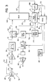
- FIG 3 there is shown one Hall effect sensor 26 of the plurality of such sensors 26 in the Hall effect sensor set 24.
- Each Hall effect sensor 26 is connected to a positive voltage source at 50, and each sensor 28 has its GND terminal 51 connected to ground.
- the output terminal 52 is connected to respective coupling capacitors 53 which are in turn connected through a line 54 to the input terminal of a respective amplifier 56.
- the capacitors 53 serve to effectively block any DC component (i.e. offset) present in the output signals of the sensors 26.
- each differential amplifier 56 is directed through the line 57 to a related band pass filter 58 which excludes certain lower frequency and higher frequency signals.
- the lower frequency signals could occur, for example, from fluctuations in the up and down or sideways movement of the belt 10.
- the higher frequency signals could result from a variety of causes a related sample and hold unit 62.
- each Hall effect sensor 26 there is for each Hall effect sensor 26 a related capacitor 53, amplifier 56, band pass filter 58 and sample and hold unit 62. Therefore, each time there is a magnetic field 26a that is generated (in response to detecting an anomaly) to activate a related sensor or sensors 26, the signal from each sensor 26 passes through the capacitor 53, to be amplified by the related amplifier 56, through the band pass filter 58 to the related sample and hold unit 62.
- the output from the sample and hold unit 62 is directed through a related line 63 to a multiplexer 64 which takes readings from all of the inputs (indicated at 65) from the various sample and hold units 62 sequentially so as to provide a single output 67.
- the sample and hold units 62 each receive an input signal at 66 to tell that sample and hold unit 62 when to sample one of the signals from the band pass filter 58.
- the output of the sample and hold units are directed to the multiplexer 64, and the output of the multiplexer 64 is through a line 67 to an analog to digital converter 68.
- a multiplex control unit 69 which provides the sampling signal at 66 to each of the sample and hold units 62. Also, this multiplex control unit 69 sends a signal through line 70 to step the multiplexer 64.
- the analog to digital converter 68 sends a flag signal through the line 72 and sends its data output through the line 73 to the processor 74.
- the flag signal through the line 72 simply indicates to the processor 74 that data is being transmitted, with the actual transmission being sent through the line 73 (as indicated previously).
- the multiplexer control unit 69 also has an output through line 75 which supplies the processor 74 with information as to the channel from which a related Hall effect sensor 26 is being transmitted.
- the processor 74 sends through the line 76 a signal to a time base generator 77 which in turn sends a timing signal through the line 78 to the multiplex control 69.
- the time base generator 77 through a line 79 sends a signal to the sine ROM 80 that translates the signal from the time base generator 77 into a digitally encoded sine wave and is transmitted through a digital to analog bit select 81 which produces a smooth since wave that passes through a low pass filter 82 and then to an amplifier 83.
- the output from the amplifier 83 is through the line 84, this being the current which drives the field coils 20 and 22 to in turn produce the magnetic fields in the yoke 18.
- timing unit 85 which is responsive to the speed of the conveyor 10, and sends a signal related to the conveyor speed to the processor 74.
- the processor 74 in turns sends a timing signal through the line 76 to the time base generator 77.
- the apparatus 16 can be provided with a temperature compensating feature.
- a Hall effect sensor 26 can be provided at a location adjacent to the other Hall effect sensors 26, so as to be responsive to a magnetic field, and as the ambient temperature changes, this particular Hall effect sensor 26 would send a reference signal to the processor 74 so that the processor 74 could make a temperature compensation for the effect the temperature would have on the various sensors 26 that are responding to anomalies in the cables 14 in the belt 10.
- the only time the sensors 26 transmit a signal is when an anomaly is being detected.
- each Hall effect sensor 26 transmits its signal through a related capacitor 53, amplifier 56, and filter 58 to a related sample and hold unit 62.
- the outputs from the various sample and hold unit 62 is directed to the multiplexer 64.
- the sensors 26 respond to a magnetic flux created by an anomaly created by an imbalance in the magnetic fields.
- the permeability of each longitudinally spaced portion of the belt is substantially the same. The result is that there is substantially no magnetic field created at the location of the sensors 26, so that the sensors 26 do not produce an output signal.
- the multiplexer 64 monitors the outputs 63 sequentially, with the stepping of the multiplexer 64 being controlled by the multiplexer control 69. Further, the multiplexer control 69 sends signals to the analog to digital computer 68. The data transmitted through the line 73 from the analog to digital computer 68 is received in the processor 74, and this data from the processor 74 can be either stored and/or displayed in some manner, or possibly be further processed to provide the desired format of the information.
- the processor 74 has additional functions, however.
- the processor 74 uses this information to send a signal to the time base generator 77, and the time base generator 77 in turn sends this information through the line to the multiplexer control 69. This information is necessary so that the multiplexer control 69 can time its actions in accordance with the linear speed of the belt 14.
- time based generator provides the signal to generate the sine waves through the sine ROM 80, digital to analog bits select 81, filter 82 and amplifier 83 to provide the execration current for the coils 20 and 22.
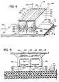
- the second embodiment of the present invention is shown in Figures 4, 5, and 6, where there is shown a portion of a conveyor belt 10 having a main body portion 12 made of a rubber-like moderately resilient material, as previously described.
- the apparatus of the second embodiment is generally designated 116, and it comprises a "W" shaped yoke 118, two field coils 120 and 122, respectively, wound around two portions 118a and 118b, respectively, of the yoke 118, and two sets 124 and 126, respectively, of Hall effect sensors 28 positioned adjacent to the two yoke portions 18a and 18b.
- the yoke 118 is positioned immediately above the belt 10 and extends transversely across the entire width of the belt 10.
- the yoke 118 comprises three vertically aligned sections, namely forward and rear sections 130 and 132 and a middle section 134.
- forward and rear sections 130 and 132 forward and rear sections 130 and 132
- middle section 134 middle section 134.
- the yoke 118 comprises a top horizontally aligned section 138 that is connected to (or made integrally with) the three vertically aligned sections 130-134.
- the lower edges 140 of the three vertical sections 30-34 are spaced a short distance above the top surface 42 of the belt 10 (e.g. an inch or less).
- the two field coils 120 and 122 are wound around the forward and rear portions 144 and 146 of the top armature section 138, and these coils 120 and 122 are connected at 144 to a source of alternating current.
- the field coils 120 and 122 generates two alternating magnetic fields one of which extends in a loop from the forward section 130, through the front top yoke portion 144, through the middle yoke section 134, and thence through the portions of the cables 14 which are positioned between the armature sections 130 and 134.
- the other alternating magnetic field extends through the rear section 134, through the adjacent portion 146 of the top armature section, through the middle armature section 134 and thence through the portions of the cables 14 that extend between the yoke sections 132 and 134.
- the Hall effect sensors 128 of the forward set 124 extend in a transverse row at evenly spaced intervals across the width of the belt 10 and are spaced a short distance (typically between 1/4 to 2 inch above the top surface 142 of the belt 10.
- the sensors 128 are positioned half way between the forward and intermediate armature sections 130 and 134, and typically, these sensors could be spaced laterally from one another about 1/4 to 1/2 inch (measured center line to center line).
- Each Hall effect sensor 128 is aligned so that its active (i.e. magnetic flux sensing) axis will intersect lines of flux extending between the lower edges 140 of the vertical sections 130 and 134 above the belt 10.
- the sensors 128 of the rear set 126 are positioned between the rear yoke section 132 and the intermediate yoke section 134 in substantially the same manner as the Hall effect sensors 128 of the forward set 124.
- the two sets 124 and 126 of the Hall effect sensors 128 could be mounted to a related printed circuit board which may contain ancillary electronics.
- the supporting structure would support the entire armature 118, coils 120 and 122 and the sensor sets 124 and 126 in a firm and rigid position that is in static proximity to the upper surface of the belt. For ease of illustration, the particular mounting device is not shown.
- each sensor 128 will be a function of the ampere turns product of the field coil 120 or 122, the sensitivity to the magnetic flux of the sensor 128 itself, the position of the sensor 128 in relation to the magnetic field lines, and the permeability of the reinforcing cables 14, and also the position of the adjacent portions of the cables 14 in relation to the magnetic field lines.
- the apparatus 116 is positioned above the belt 10 as shown in Figures 1 and 2 (and as described above), and the alternating current is imposed on the two windings or the two field coils 120 and 122. Then the conveyor belt 10 is set in motion so that it travels longitudinally beneath the apparatus 116.
- the Hall effect sensors 128 of the two sets 124 and 126 are monitored to sense any change in the strength of that portion of the magnetic field extending through the Hall effect sensors 128.
- each sensor 128 bears an inverse relationship to the permeability of the adjacent portions of the reinforcing cables 14 and to the position of the adjacent portions of the cables 14 in relation to the magnetic field lines.
- the magnitude of the output of the sensor 128 is a direct function of the strength of any intersecting magnetic flux (i.e. field lines). Therefore, as indicated above, the absence of any permeable material in the magnetic field generated by either of the coils 120 or 122 will appear as a strong flux (maximum field line intersection) and thereby produce the highest output. The presence of any permeable material will produce a path of lesser reluctance for the magnetic lines of force to follow and will thereby reduce the magnitude of the flux encountered by the Hall effect sensor 128, and correspondingly reduce the magnitude of its output.
- the frequency of the energizing current in the yoke 118 is controlled, relative to the longitudinal spacing of the two Hall effect sensor sets 124 and 126 and also relative to the linear speed of the belt 10 so that the time interval of each sine wave is equal to the time it takes one portion of the belt 10 to travel from a location below one Hall effect sensor set 126 to the other Hall effect sensor 124.
- the belt is fluttering in a manner that it has moved upwardly a short distance and is more closely adjacent to the two sets of the Hall effect sensors 128. This would normally be expected to lessen the strength of the portion of the magnetic fields that pass through the two sets of Hall effect sensors 128.
- the sensing apparatus is able to compare the two sine wave portions imposed on that particular field coil 120 or 122 at the time that a given portion of the cable is beneath first the rear set 126 of sensors 128 and then under the forward set 124 of the sensors 128. If the amplitude of these two sine waves varies to the same degree, then this would indicate a condition where the belt 10 has moved either closer to or further away from the Hall effect sensors 128. The manner in which this is done will be described more fully later when the circuitry of the present invention is described relative to Figure 6.
- this anomaly will have moved from eneath the rear Hall effect sensor set 126 to beneath the forward Hall effect sensor set 124, and at this time this anomaly will affect the pattern of the magnetic field in the forward yoke section 118a differently from an undamaged cable portion, and this will be detected in a Hall effect sensor of the forward set 124.
- the control circuitry of the prsent invention is able to distinguish that situation from that of which the change in the field strength is merely due to the flutter.
- the "fingerprint" of the detected signal will vary, depending upon the type of anomaly which is being detected. For example, if there is a distinct break in the cable 14, the duration of time during which this break moves from beneath the rear sensor set 126 to the forward sensor sets is relatively short and the changes in the magnetic field could be two rather abrupt changes closer in time sequence. ON the other hand, let us assume that the anomaly is an extended area of corrosion which would pass between the two sensor sets 124 and 126 over a more extended interval of time. This wqould produce a significantly different fingerprint that would extend over a longer time interval. By analysing the configuration and duration fo the signal created by the anomaly, the nature of the anomaly can be more closely ascertained.
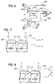
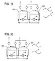
- FIG. 6 The circuitry of the second embodiment is quite similar to that of the first embodiment, except in the manner in which the signals from the Hall effect sensor sets 124 and 126 are initially processed.
- the field prodsuced by the forward field coil is indicated at 120a, and that produced by the rear field coil is designated 122a. It can be seen that these magnetic fields 120a and 122a intersect the Hall effect sensors 128 of the forward and rear sets 124 and 126.
- Each Hall effect sensor 128 is, as in the first embodiment, connected to a positive voltage source at 150, and each sensor 128 has its GND terminat 152 connected to ground.
- the output terminals 152 are connected to respective coupling capacitors 153 which are in turn connected through lines 154 and 155 to the input terminals of a differential amplifier 156.
- each of which connects to respective band pass filters 158 so that each pair of a forward and rear sensor is connected to its related differential amplifier 156 and filter 158.
- the differential amplifier 156 detects a difference in these two sine waves. A difference in the two sine waves would ordinarily indicate some sort of an anomaly. On the other hand, if the sine waves change in amplitude simultaneously (due to the fluttering of the belt) this would not produce an output from the differential amplifiers 156.
- the potential problem of the futter of the belt effecting the strength of the signals is alleviated, and the differential amplifier 156 generates a signal only when there is an anomaly, such as from damage to the cables 14 or a splkice in the cables 14.
- circuitry for this embodiment is substantially the same as described in Figure 3 with reference to the first embodiment. Accordingly, it is believed that no further description of this circuitry of the second embodiment is needed.
Landscapes
- Chemical & Material Sciences (AREA)
- Analytical Chemistry (AREA)
- Electrochemistry (AREA)
- Physics & Mathematics (AREA)
- Health & Medical Sciences (AREA)
- Life Sciences & Earth Sciences (AREA)
- Chemical Kinetics & Catalysis (AREA)
- Biochemistry (AREA)
- General Health & Medical Sciences (AREA)
- General Physics & Mathematics (AREA)
- Immunology (AREA)
- Pathology (AREA)
- Control Of Conveyors (AREA)
- Investigating Or Analyzing Materials By The Use Of Magnetic Means (AREA)
Applications Claiming Priority (2)
| Application Number | Priority Date | Filing Date | Title |
|---|---|---|---|
| US07/954,485 US5570017A (en) | 1992-09-30 | 1992-09-30 | Apparatus and method of damage detection for magnetically permeable members using an alternating magnetic field and hall effect sensors |
| US954485 | 1992-09-30 |
Publications (2)
| Publication Number | Publication Date |
|---|---|
| EP0590734A2 true EP0590734A2 (de) | 1994-04-06 |
| EP0590734A3 EP0590734A3 (de) | 1994-04-13 |
Family
ID=25495481
Family Applications (1)
| Application Number | Title | Priority Date | Filing Date |
|---|---|---|---|
| EP19930202794 Withdrawn EP0590734A3 (de) | 1992-09-30 | 1993-09-30 | Gerät und Methode zur Fehlerdetektion magnetisch permeabler Teile |
Country Status (5)
| Country | Link |
|---|---|
| US (2) | US5570017A (de) |
| EP (1) | EP0590734A3 (de) |
| JP (1) | JPH06317563A (de) |
| AU (1) | AU675453B2 (de) |
| CA (1) | CA2107389A1 (de) |
Cited By (5)
| Publication number | Priority date | Publication date | Assignee | Title |
|---|---|---|---|---|
| GB2429789A (en) * | 2005-09-01 | 2007-03-07 | Fenner Dunlop Ltd | Conveyor belt monitoring |
| WO2008090521A1 (en) * | 2007-01-26 | 2008-07-31 | Advanced Imaging Technologies (Proprietary) Limited | Monitoring of conveyor belts |
| EP2238433A4 (de) * | 2008-01-16 | 2011-03-02 | Gates Corp A Delaware U S A Corp | Riemen-überwachungssysteme und -verfahren |
| EP2095102A4 (de) * | 2006-10-17 | 2014-05-21 | Athena Ind Technologies Inc | Untersuchungsvorrichtung und -verfahren |
| ITUB20156789A1 (it) * | 2015-12-11 | 2017-06-11 | Uniset S R L | Kit di monitoraggio di nastri trasportatori e simili, e relativo procedimento. |
Families Citing this family (36)
| Publication number | Priority date | Publication date | Assignee | Title |
|---|---|---|---|---|
| US5570017A (en) * | 1992-09-30 | 1996-10-29 | Canada Conveyor Belt Co., Inc. | Apparatus and method of damage detection for magnetically permeable members using an alternating magnetic field and hall effect sensors |
| PL191431B1 (pl) * | 1998-02-13 | 2006-05-31 | Phoenix Ag | Urządzenie do ciągłego monitorowania połączenia pasa przenośnikowego |
| KR100361568B1 (ko) * | 1998-12-29 | 2003-01-24 | 주식회사 포스코 | 벨트 컨베이어의 벨트 절손 감지장치 |
| US6633159B1 (en) * | 1999-03-29 | 2003-10-14 | Otis Elevator Company | Method and apparatus for magnetic detection of degradation of jacketed elevator rope |
| EP1308721B1 (de) * | 2001-11-02 | 2006-07-26 | Corus Technology BV | Verfahren und Vorrichtung zur Erfassung magnetischer Eigenschaften metallischer Gegenstände |
| US7112960B2 (en) | 2003-07-31 | 2006-09-26 | Applied Materials, Inc. | Eddy current system for in-situ profile measurement |
| US7451657B2 (en) * | 2004-01-16 | 2008-11-18 | Jentek Sensors, Inc. | Material condition monitoring with multiple sensing modes |
| EP1846741A4 (de) * | 2004-03-16 | 2009-09-16 | Otis Elevator Co | Zuglaststärkenüberwachungssystem und verfahren |
| US7443156B2 (en) * | 2004-07-19 | 2008-10-28 | Pruftechnik Dieter Busch Ag | Apparatus and method for identifying defects on objects or for locating objects |
| US7894934B2 (en) * | 2006-12-05 | 2011-02-22 | Veyance Technologies, Inc. | Remote conveyor belt monitoring system and method |
| US7690354B2 (en) * | 2006-12-05 | 2010-04-06 | Ford Global Technologies, Llc | System and method for improving operation of a fuel injector at lower temperatures |
| US7810634B2 (en) * | 2008-08-04 | 2010-10-12 | Veyance Technologies Inc. | Sensor system for a conveyor belt |
| WO2010033529A1 (en) | 2008-09-19 | 2010-03-25 | Fenner Dunlop Americas, Inc. | System and method for controlling a conveyor belt condition monitoring system |
| JP5615831B2 (ja) * | 2008-11-14 | 2014-10-29 | アプライド マテリアルズ インコーポレイテッドApplied Materials,Incorporated | 縁部分解能強化渦電流センサ |
| FR2940685B1 (fr) * | 2008-12-31 | 2011-03-18 | Michelin Soc Tech | Dispositif de controle de fils metalliques |
| KR20100083565A (ko) * | 2009-01-14 | 2010-07-22 | 한재형 | 타이밍벨트의 파단 감지장치 |
| DE102012017871A1 (de) * | 2012-09-06 | 2014-03-06 | Institut Dr. Foerster Gmbh & Co. Kg | Differentieller Sensor und Verfahren zur Detektion von Anomalien in elektrisch leitfähigen Materialien |
| PL2876063T3 (pl) * | 2013-11-25 | 2017-07-31 | Veyance Technologies, Inc. | Sposób monitorowania połączeń taśmy przenośnikowej |
| US20150239708A1 (en) * | 2014-02-25 | 2015-08-27 | Thyssenkrupp Elevator Ag | System and Method for Monitoring a Load Bearing Member |
| DE102014103684A1 (de) * | 2014-03-18 | 2015-09-24 | Sensitec Gmbh | Magnetfeldsensoranordnung |
| CN104016099B (zh) * | 2014-05-23 | 2016-04-13 | 爱德森(厦门)电子有限公司 | 钢丝绳输送带纵向撕裂损伤在线涡流监测方法 |
| JP6452130B2 (ja) * | 2015-03-13 | 2019-01-16 | 株式会社三井E&Sマシナリー | 線状部材の診断装置及び診断方法 |
| WO2017023235A1 (en) * | 2015-07-31 | 2017-02-09 | Compagnie Generale Des Etablissements Michelin | Device and method for inspection of polymeric material with ferrous reinforcement |
| KR102008172B1 (ko) * | 2015-08-19 | 2019-08-07 | 미쓰비시덴키 가부시키가이샤 | 와이어 로프 손상 검출 장치 및 조정 지그 |
| CN105548350B (zh) * | 2016-01-26 | 2018-12-25 | 江苏理工学院 | 基于圆角矩形阵列探头的脉冲涡流缺陷检测成像系统 |
| US10724992B2 (en) * | 2016-03-24 | 2020-07-28 | Mitsubishi Electric Corporation | Wire rope flaw detector and adjustment method therefor |
| CA2970509C (en) * | 2016-09-01 | 2025-09-16 | Maurice Bernard Dusseault | SYSTEM AND METHOD FOR DETECTING IRREGULARITIES IN REINFORCED CONCRETE REINFORCEMENT BAR |
| WO2018080764A1 (en) | 2016-10-28 | 2018-05-03 | Applied Materials, Inc. | Core configuration with alternating posts for in-situ electromagnetic induction monitoring system |
| CN107377424B (zh) * | 2017-09-19 | 2023-05-23 | 长电科技(滁州)有限公司 | 一种霍尔线圈和基于霍尔线圈的霍尔产品测试线圈装置及测试方法 |
| CN108082886B (zh) * | 2018-01-15 | 2024-03-15 | 洛阳威尔若普检测技术有限公司 | 一种钢丝绳芯传送带自动监测系统及监测方法 |
| JP7187855B2 (ja) * | 2018-07-11 | 2022-12-13 | 株式会社島津製作所 | 磁性体検査システム、磁性体検査装置および磁性体検査方法 |
| CN109520916A (zh) * | 2018-12-14 | 2019-03-26 | 天津大学 | 定量表征混凝土中钢筋锈蚀程度的电磁感应装置及方法 |
| US11480546B2 (en) | 2020-12-23 | 2022-10-25 | Shimadzu Corporation | Magnetic material inspection system, magnetic material inspection device, and magnetic material inspection method |
| CN112798682B (zh) * | 2021-04-07 | 2021-07-02 | 山东大业股份有限公司 | 一种胎圈钢丝质量检测装置 |
| CN113820386B (zh) | 2021-09-03 | 2024-12-13 | 威海华菱光电股份有限公司 | 钢丝帘布缺陷检测装置 |
| IT202200025839A1 (it) * | 2022-12-16 | 2024-06-16 | Iobelt Srl | Nastro multistrato per trasportatore a nastro, trasportatore a nastro, sistema e metodo per gestire e monitorare il trasporto di un oggetto e l’interazione di un operatore con il nastro multistrato |
Family Cites Families (9)
| Publication number | Priority date | Publication date | Assignee | Title |
|---|---|---|---|---|
| AU535356B2 (en) * | 1979-10-15 | 1984-03-15 | Commonwealth Scientific And Industrial Research Organisation | Conveyor belt wear monitor |
| JPS56148052A (en) * | 1980-04-21 | 1981-11-17 | Hitachi Elevator Eng & Serv Co Ltd | Electromagnetic flaw detector for continuous magnetic material |
| DE3228669A1 (de) * | 1982-07-31 | 1984-02-02 | Basf Ag, 6700 Ludwigshafen | Verfahren zur herstellung nadelfoermiger, im wesentlichen aus eisen bestehender ferromagnetischer metallteilchen |
| JPH073408B2 (ja) * | 1985-03-29 | 1995-01-18 | 日本鋼管株式会社 | パイプラインの孔食検出装置 |
| GB8606564D0 (en) * | 1986-03-17 | 1986-04-23 | Atomic Energy Authority Uk | Magnetic discontinuity detection |
| ZA871964B (de) * | 1986-03-25 | 1987-09-07 | ||
| US5036277A (en) * | 1987-11-23 | 1991-07-30 | Crucible Societe Anonyme | Method of and apparatus for detecting cross sectional area variations in an elongate object by the non-inductive measurement of radial flux variations |
| GB9100589D0 (en) * | 1991-01-11 | 1991-02-27 | Technical Software Consultants | A.c.field measurement testing system |
| US5570017A (en) * | 1992-09-30 | 1996-10-29 | Canada Conveyor Belt Co., Inc. | Apparatus and method of damage detection for magnetically permeable members using an alternating magnetic field and hall effect sensors |
-
1992
- 1992-09-30 US US07/954,485 patent/US5570017A/en not_active Expired - Fee Related
-
1993
- 1993-09-28 AU AU48629/93A patent/AU675453B2/en not_active Ceased
- 1993-09-30 CA CA002107389A patent/CA2107389A1/en not_active Abandoned
- 1993-09-30 EP EP19930202794 patent/EP0590734A3/de not_active Withdrawn
- 1993-09-30 JP JP5244384A patent/JPH06317563A/ja active Pending
-
1995
- 1995-03-29 US US08/412,695 patent/US5847563A/en not_active Expired - Fee Related
Cited By (11)
| Publication number | Priority date | Publication date | Assignee | Title |
|---|---|---|---|---|
| GB2429789A (en) * | 2005-09-01 | 2007-03-07 | Fenner Dunlop Ltd | Conveyor belt monitoring |
| GB2429789B (en) * | 2005-09-01 | 2009-09-23 | Fenner Dunlop Ltd | Conveyor belt monitoring |
| US8074789B2 (en) | 2005-09-01 | 2011-12-13 | Fenner Dunlop Limited | Conveyor belt monitoring |
| EP2095102A4 (de) * | 2006-10-17 | 2014-05-21 | Athena Ind Technologies Inc | Untersuchungsvorrichtung und -verfahren |
| WO2008090521A1 (en) * | 2007-01-26 | 2008-07-31 | Advanced Imaging Technologies (Proprietary) Limited | Monitoring of conveyor belts |
| WO2008090522A1 (en) * | 2007-01-26 | 2008-07-31 | Advanced Imaging Technologies (Proprietary) Limited | Monitoring of conveyor belts |
| US8177051B2 (en) | 2007-01-26 | 2012-05-15 | Advanced Imaging Technologies (Proprietary) Limited | Monitoring of conveyor belts |
| AU2008208577B2 (en) * | 2007-01-26 | 2013-04-11 | ContiTech Services (Pty.) Ltd. | Monitoring of conveyor belts |
| US8436607B2 (en) | 2007-01-26 | 2013-05-07 | Advanced Imaging Technologies (Proprietary) Limited | Monitoring of conveyor belts |
| EP2238433A4 (de) * | 2008-01-16 | 2011-03-02 | Gates Corp A Delaware U S A Corp | Riemen-überwachungssysteme und -verfahren |
| ITUB20156789A1 (it) * | 2015-12-11 | 2017-06-11 | Uniset S R L | Kit di monitoraggio di nastri trasportatori e simili, e relativo procedimento. |
Also Published As
| Publication number | Publication date |
|---|---|
| AU4862993A (en) | 1994-04-14 |
| US5570017A (en) | 1996-10-29 |
| CA2107389A1 (en) | 1994-03-31 |
| AU675453B2 (en) | 1997-02-06 |
| JPH06317563A (ja) | 1994-11-15 |
| US5847563A (en) | 1998-12-08 |
| EP0590734A3 (de) | 1994-04-13 |
Similar Documents
| Publication | Publication Date | Title |
|---|---|---|
| US5570017A (en) | Apparatus and method of damage detection for magnetically permeable members using an alternating magnetic field and hall effect sensors | |
| US5426362A (en) | Damage detection apparatus and method for a conveyor belt having magnetically permeable members | |
| US9199800B2 (en) | Monitoring of conveyor belts | |
| CA1038037A (en) | Magnetic testing device for detecting defects in elongated objects | |
| EP0260355B1 (de) | Vorrichtung zur Erfassung von innerlichen Oberflächenfehlern jedes Rohres der eine Rohrleitung bildet | |
| CA2871973C (en) | Method for monitoring conveyor belt splices | |
| US20130024135A1 (en) | Method And Apparatus For Ferromagnetic Cable Inspection | |
| WO2002040384A1 (en) | Conveyor belt fault detection apparatus and method | |
| JPWO2009011306A1 (ja) | コンベアベルトのモニタリングシステム | |
| CN113820386B (zh) | 钢丝帘布缺陷检测装置 | |
| KR970075949A (ko) | 금속 탐지기 시스템 | |
| US7055738B2 (en) | Device for accepting banknotes | |
| KR101670427B1 (ko) | 외란에 강인한 고감도 금속검출기 | |
| US5471138A (en) | Inductive valve motion sensor for positioning outside the body of the valve | |
| JP3819903B2 (ja) | 金属検出装置 | |
| Harrison | A magnetic transducer for testing steel-cord deterioration in high-tensile strength conveyor belts | |
| AU2006337950B2 (en) | Method for monitoring and/or testing without destruction a transmission element, and measuring arrangement for carrying out the method | |
| Kuzik et al. | Scanning steel cord conveyor belts with the BELT C. A. T. MDR system | |
| CN215894477U (zh) | 钢丝帘布缺陷检测装置 | |
| JP4156577B2 (ja) | 金属検出装置 | |
| JPH1072111A (ja) | コンベヤベルトのスチールコード断線検出方法及び装置 | |
| CA1242504A (en) | Device for the detection of longitudinal cracking in conveyor belt | |
| JPS6015312A (ja) | コンベヤベルトの縦裂け検出装置 | |
| KR100298597B1 (ko) | 원료이송용컨베이어벨트상의금속편검출방법및그의장치 | |
| Harrison | Monitoring broken steel cables in moving elastomer belts |
Legal Events
| Date | Code | Title | Description |
|---|---|---|---|
| PUAI | Public reference made under article 153(3) epc to a published international application that has entered the european phase |
Free format text: ORIGINAL CODE: 0009012 |
|
| PUAL | Search report despatched |
Free format text: ORIGINAL CODE: 0009013 |
|
| AK | Designated contracting states |
Kind code of ref document: A2 Designated state(s): DE FR GB |
|
| AK | Designated contracting states |
Kind code of ref document: A3 Designated state(s): DE FR GB |
|
| 17P | Request for examination filed |
Effective date: 19941013 |
|
| 17Q | First examination report despatched |
Effective date: 19970904 |
|
| APAB | Appeal dossier modified |
Free format text: ORIGINAL CODE: EPIDOS NOAPE |
|
| APAB | Appeal dossier modified |
Free format text: ORIGINAL CODE: EPIDOS NOAPE |
|
| APAD | Appeal reference recorded |
Free format text: ORIGINAL CODE: EPIDOS REFNE |
|
| APCB | Communication from the board of appeal sent |
Free format text: ORIGINAL CODE: EPIDOS OBAPE |
|
| APCB | Communication from the board of appeal sent |
Free format text: ORIGINAL CODE: EPIDOS OBAPE |
|
| APCB | Communication from the board of appeal sent |
Free format text: ORIGINAL CODE: EPIDOS OBAPE |
|
| APAB | Appeal dossier modified |
Free format text: ORIGINAL CODE: EPIDOS NOAPE |
|
| GRAG | Despatch of communication of intention to grant |
Free format text: ORIGINAL CODE: EPIDOS AGRA |
|
| GRAH | Despatch of communication of intention to grant a patent |
Free format text: ORIGINAL CODE: EPIDOS IGRA |
|
| RTI1 | Title (correction) |
Free format text: APPARATUS OF DAMAGE DETECTION FOR MAGNETICALLY PERMEABLE MEMBERS |
|
| 18D | Application deemed to be withdrawn |
Effective date: 20011208 |
|
| APAF | Appeal reference modified |
Free format text: ORIGINAL CODE: EPIDOSCREFNE |