EP0590814B1 - Système de contrÔle d'émission de particules et de gaz d'échappement - Google Patents
Système de contrÔle d'émission de particules et de gaz d'échappement Download PDFInfo
- Publication number
- EP0590814B1 EP0590814B1 EP93307094A EP93307094A EP0590814B1 EP 0590814 B1 EP0590814 B1 EP 0590814B1 EP 93307094 A EP93307094 A EP 93307094A EP 93307094 A EP93307094 A EP 93307094A EP 0590814 B1 EP0590814 B1 EP 0590814B1
- Authority
- EP
- European Patent Office
- Prior art keywords
- fuel
- additive
- fuel tank
- tank
- control system
- Prior art date
- Legal status (The legal status is an assumption and is not a legal conclusion. Google has not performed a legal analysis and makes no representation as to the accuracy of the status listed.)
- Expired - Lifetime
Links
Images

Classifications
-
- F—MECHANICAL ENGINEERING; LIGHTING; HEATING; WEAPONS; BLASTING
- F02—COMBUSTION ENGINES; HOT-GAS OR COMBUSTION-PRODUCT ENGINE PLANTS
- F02M—SUPPLYING COMBUSTION ENGINES IN GENERAL WITH COMBUSTIBLE MIXTURES OR CONSTITUENTS THEREOF
- F02M25/00—Engine-pertinent apparatus for adding non-fuel substances or small quantities of secondary fuel to combustion-air, main fuel or fuel-air mixture
- F02M25/14—Engine-pertinent apparatus for adding non-fuel substances or small quantities of secondary fuel to combustion-air, main fuel or fuel-air mixture adding anti-knock agents, not provided for in subgroups F02M25/022 - F02M25/10
-
- B—PERFORMING OPERATIONS; TRANSPORTING
- B01—PHYSICAL OR CHEMICAL PROCESSES OR APPARATUS IN GENERAL
- B01D—SEPARATION
- B01D53/00—Separation of gases or vapours; Recovering vapours of volatile solvents from gases; Chemical or biological purification of waste gases, e.g. engine exhaust gases, smoke, fumes, flue gases, aerosols
- B01D53/34—Chemical or biological purification of waste gases
- B01D53/92—Chemical or biological purification of waste gases of engine exhaust gases
- B01D53/94—Chemical or biological purification of waste gases of engine exhaust gases by catalytic processes
- B01D53/944—Simultaneously removing carbon monoxide, hydrocarbons or carbon making use of oxidation catalysts
-
- B—PERFORMING OPERATIONS; TRANSPORTING
- B01—PHYSICAL OR CHEMICAL PROCESSES OR APPARATUS IN GENERAL
- B01J—CHEMICAL OR PHYSICAL PROCESSES, e.g. CATALYSIS OR COLLOID CHEMISTRY; THEIR RELEVANT APPARATUS
- B01J4/00—Feed or outlet devices; Feed or outlet control devices
- B01J4/02—Feed or outlet devices; Feed or outlet control devices for feeding measured, i.e. prescribed quantities of reagents
-
- B—PERFORMING OPERATIONS; TRANSPORTING
- B60—VEHICLES IN GENERAL
- B60K—ARRANGEMENT OR MOUNTING OF PROPULSION UNITS OR OF TRANSMISSIONS IN VEHICLES; ARRANGEMENT OR MOUNTING OF PLURAL DIVERSE PRIME-MOVERS IN VEHICLES; AUXILIARY DRIVES FOR VEHICLES; INSTRUMENTATION OR DASHBOARDS FOR VEHICLES; ARRANGEMENTS IN CONNECTION WITH COOLING, AIR INTAKE, GAS EXHAUST OR FUEL SUPPLY OF PROPULSION UNITS IN VEHICLES
- B60K15/00—Arrangement in connection with fuel supply of combustion engines or other fuel consuming energy converters, e.g. fuel cells; Mounting or construction of fuel tanks
- B60K15/03—Fuel tanks
- B60K15/063—Arrangement of tanks
-
- C—CHEMISTRY; METALLURGY
- C10—PETROLEUM, GAS OR COKE INDUSTRIES; TECHNICAL GASES CONTAINING CARBON MONOXIDE; FUELS; LUBRICANTS; PEAT
- C10L—FUELS NOT OTHERWISE PROVIDED FOR; NATURAL GAS; SYNTHETIC NATURAL GAS OBTAINED BY PROCESSES NOT COVERED BY SUBCLASSES C10G OR C10K; LIQUIFIED PETROLEUM GAS; USE OF ADDITIVES TO FUELS OR FIRES; FIRE-LIGHTERS
- C10L1/00—Liquid carbonaceous fuels
- C10L1/10—Liquid carbonaceous fuels containing additives
- C10L1/14—Organic compounds
- C10L1/18—Organic compounds containing oxygen
- C10L1/188—Carboxylic acids; metal salts thereof
- C10L1/1881—Carboxylic acids; metal salts thereof carboxylic group attached to an aliphatic carbon atom
-
- C—CHEMISTRY; METALLURGY
- C10—PETROLEUM, GAS OR COKE INDUSTRIES; TECHNICAL GASES CONTAINING CARBON MONOXIDE; FUELS; LUBRICANTS; PEAT
- C10L—FUELS NOT OTHERWISE PROVIDED FOR; NATURAL GAS; SYNTHETIC NATURAL GAS OBTAINED BY PROCESSES NOT COVERED BY SUBCLASSES C10G OR C10K; LIQUIFIED PETROLEUM GAS; USE OF ADDITIVES TO FUELS OR FIRES; FIRE-LIGHTERS
- C10L1/00—Liquid carbonaceous fuels
- C10L1/10—Liquid carbonaceous fuels containing additives
- C10L1/14—Organic compounds
- C10L1/30—Organic compounds compounds not mentioned before (complexes)
-
- C—CHEMISTRY; METALLURGY
- C10—PETROLEUM, GAS OR COKE INDUSTRIES; TECHNICAL GASES CONTAINING CARBON MONOXIDE; FUELS; LUBRICANTS; PEAT
- C10L—FUELS NOT OTHERWISE PROVIDED FOR; NATURAL GAS; SYNTHETIC NATURAL GAS OBTAINED BY PROCESSES NOT COVERED BY SUBCLASSES C10G OR C10K; LIQUIFIED PETROLEUM GAS; USE OF ADDITIVES TO FUELS OR FIRES; FIRE-LIGHTERS
- C10L10/00—Use of additives to fuels or fires for particular purposes
- C10L10/02—Use of additives to fuels or fires for particular purposes for reducing smoke development
-
- C—CHEMISTRY; METALLURGY
- C10—PETROLEUM, GAS OR COKE INDUSTRIES; TECHNICAL GASES CONTAINING CARBON MONOXIDE; FUELS; LUBRICANTS; PEAT
- C10L—FUELS NOT OTHERWISE PROVIDED FOR; NATURAL GAS; SYNTHETIC NATURAL GAS OBTAINED BY PROCESSES NOT COVERED BY SUBCLASSES C10G OR C10K; LIQUIFIED PETROLEUM GAS; USE OF ADDITIVES TO FUELS OR FIRES; FIRE-LIGHTERS
- C10L10/00—Use of additives to fuels or fires for particular purposes
- C10L10/06—Use of additives to fuels or fires for particular purposes for facilitating soot removal
-
- F—MECHANICAL ENGINEERING; LIGHTING; HEATING; WEAPONS; BLASTING
- F01—MACHINES OR ENGINES IN GENERAL; ENGINE PLANTS IN GENERAL; STEAM ENGINES
- F01N—GAS-FLOW SILENCERS OR EXHAUST APPARATUS FOR MACHINES OR ENGINES IN GENERAL; GAS-FLOW SILENCERS OR EXHAUST APPARATUS FOR INTERNAL-COMBUSTION ENGINES
- F01N3/00—Exhaust or silencing apparatus having means for purifying, rendering innocuous, or otherwise treating exhaust
- F01N3/02—Exhaust or silencing apparatus having means for purifying, rendering innocuous, or otherwise treating exhaust for cooling, or for removing solid constituents of, exhaust
- F01N3/021—Exhaust or silencing apparatus having means for purifying, rendering innocuous, or otherwise treating exhaust for cooling, or for removing solid constituents of, exhaust by means of filters
- F01N3/022—Exhaust or silencing apparatus having means for purifying, rendering innocuous, or otherwise treating exhaust for cooling, or for removing solid constituents of, exhaust by means of filters characterised by specially adapted filtering structure, e.g. honeycomb, mesh or fibrous
- F01N3/0222—Exhaust or silencing apparatus having means for purifying, rendering innocuous, or otherwise treating exhaust for cooling, or for removing solid constituents of, exhaust by means of filters characterised by specially adapted filtering structure, e.g. honeycomb, mesh or fibrous the structure being monolithic, e.g. honeycombs
-
- F—MECHANICAL ENGINEERING; LIGHTING; HEATING; WEAPONS; BLASTING
- F01—MACHINES OR ENGINES IN GENERAL; ENGINE PLANTS IN GENERAL; STEAM ENGINES
- F01N—GAS-FLOW SILENCERS OR EXHAUST APPARATUS FOR MACHINES OR ENGINES IN GENERAL; GAS-FLOW SILENCERS OR EXHAUST APPARATUS FOR INTERNAL-COMBUSTION ENGINES
- F01N3/00—Exhaust or silencing apparatus having means for purifying, rendering innocuous, or otherwise treating exhaust
- F01N3/02—Exhaust or silencing apparatus having means for purifying, rendering innocuous, or otherwise treating exhaust for cooling, or for removing solid constituents of, exhaust
- F01N3/021—Exhaust or silencing apparatus having means for purifying, rendering innocuous, or otherwise treating exhaust for cooling, or for removing solid constituents of, exhaust by means of filters
- F01N3/023—Exhaust or silencing apparatus having means for purifying, rendering innocuous, or otherwise treating exhaust for cooling, or for removing solid constituents of, exhaust by means of filters using means for regenerating the filters, e.g. by burning trapped particles
-
- F—MECHANICAL ENGINEERING; LIGHTING; HEATING; WEAPONS; BLASTING
- F01—MACHINES OR ENGINES IN GENERAL; ENGINE PLANTS IN GENERAL; STEAM ENGINES
- F01N—GAS-FLOW SILENCERS OR EXHAUST APPARATUS FOR MACHINES OR ENGINES IN GENERAL; GAS-FLOW SILENCERS OR EXHAUST APPARATUS FOR INTERNAL-COMBUSTION ENGINES
- F01N3/00—Exhaust or silencing apparatus having means for purifying, rendering innocuous, or otherwise treating exhaust
- F01N3/08—Exhaust or silencing apparatus having means for purifying, rendering innocuous, or otherwise treating exhaust for rendering innocuous
- F01N3/10—Exhaust or silencing apparatus having means for purifying, rendering innocuous, or otherwise treating exhaust for rendering innocuous by thermal or catalytic conversion of noxious components of exhaust
- F01N3/24—Exhaust or silencing apparatus having means for purifying, rendering innocuous, or otherwise treating exhaust for rendering innocuous by thermal or catalytic conversion of noxious components of exhaust characterised by constructional aspects of converting apparatus
- F01N3/28—Construction of catalytic reactors
- F01N3/2882—Catalytic reactors combined or associated with other devices, e.g. exhaust silencers or other exhaust purification devices
-
- F—MECHANICAL ENGINEERING; LIGHTING; HEATING; WEAPONS; BLASTING
- F02—COMBUSTION ENGINES; HOT-GAS OR COMBUSTION-PRODUCT ENGINE PLANTS
- F02D—CONTROLLING COMBUSTION ENGINES
- F02D19/00—Controlling engines characterised by their use of non-liquid fuels, pluralities of fuels, or non-fuel substances added to the combustible mixtures
- F02D19/12—Controlling engines characterised by their use of non-liquid fuels, pluralities of fuels, or non-fuel substances added to the combustible mixtures peculiar to engines working with non-fuel substances or with anti-knock agents, e.g. with anti-knock fuel
-
- F—MECHANICAL ENGINEERING; LIGHTING; HEATING; WEAPONS; BLASTING
- F02—COMBUSTION ENGINES; HOT-GAS OR COMBUSTION-PRODUCT ENGINE PLANTS
- F02M—SUPPLYING COMBUSTION ENGINES IN GENERAL WITH COMBUSTIBLE MIXTURES OR CONSTITUENTS THEREOF
- F02M25/00—Engine-pertinent apparatus for adding non-fuel substances or small quantities of secondary fuel to combustion-air, main fuel or fuel-air mixture
-
- B—PERFORMING OPERATIONS; TRANSPORTING
- B60—VEHICLES IN GENERAL
- B60K—ARRANGEMENT OR MOUNTING OF PROPULSION UNITS OR OF TRANSMISSIONS IN VEHICLES; ARRANGEMENT OR MOUNTING OF PLURAL DIVERSE PRIME-MOVERS IN VEHICLES; AUXILIARY DRIVES FOR VEHICLES; INSTRUMENTATION OR DASHBOARDS FOR VEHICLES; ARRANGEMENTS IN CONNECTION WITH COOLING, AIR INTAKE, GAS EXHAUST OR FUEL SUPPLY OF PROPULSION UNITS IN VEHICLES
- B60K15/00—Arrangement in connection with fuel supply of combustion engines or other fuel consuming energy converters, e.g. fuel cells; Mounting or construction of fuel tanks
- B60K15/03—Fuel tanks
- B60K2015/03328—Arrangements or special measures related to fuel tanks or fuel handling
- B60K2015/03348—Arrangements or special measures related to fuel tanks or fuel handling for supplying additives to fuel
-
- C—CHEMISTRY; METALLURGY
- C10—PETROLEUM, GAS OR COKE INDUSTRIES; TECHNICAL GASES CONTAINING CARBON MONOXIDE; FUELS; LUBRICANTS; PEAT
- C10L—FUELS NOT OTHERWISE PROVIDED FOR; NATURAL GAS; SYNTHETIC NATURAL GAS OBTAINED BY PROCESSES NOT COVERED BY SUBCLASSES C10G OR C10K; LIQUIFIED PETROLEUM GAS; USE OF ADDITIVES TO FUELS OR FIRES; FIRE-LIGHTERS
- C10L1/00—Liquid carbonaceous fuels
- C10L1/10—Liquid carbonaceous fuels containing additives
- C10L1/14—Organic compounds
- C10L1/16—Hydrocarbons
- C10L1/1608—Well defined compounds, e.g. hexane, benzene
-
- C—CHEMISTRY; METALLURGY
- C10—PETROLEUM, GAS OR COKE INDUSTRIES; TECHNICAL GASES CONTAINING CARBON MONOXIDE; FUELS; LUBRICANTS; PEAT
- C10L—FUELS NOT OTHERWISE PROVIDED FOR; NATURAL GAS; SYNTHETIC NATURAL GAS OBTAINED BY PROCESSES NOT COVERED BY SUBCLASSES C10G OR C10K; LIQUIFIED PETROLEUM GAS; USE OF ADDITIVES TO FUELS OR FIRES; FIRE-LIGHTERS
- C10L1/00—Liquid carbonaceous fuels
- C10L1/10—Liquid carbonaceous fuels containing additives
- C10L1/14—Organic compounds
- C10L1/30—Organic compounds compounds not mentioned before (complexes)
- C10L1/301—Organic compounds compounds not mentioned before (complexes) derived from metals
-
- C—CHEMISTRY; METALLURGY
- C10—PETROLEUM, GAS OR COKE INDUSTRIES; TECHNICAL GASES CONTAINING CARBON MONOXIDE; FUELS; LUBRICANTS; PEAT
- C10L—FUELS NOT OTHERWISE PROVIDED FOR; NATURAL GAS; SYNTHETIC NATURAL GAS OBTAINED BY PROCESSES NOT COVERED BY SUBCLASSES C10G OR C10K; LIQUIFIED PETROLEUM GAS; USE OF ADDITIVES TO FUELS OR FIRES; FIRE-LIGHTERS
- C10L1/00—Liquid carbonaceous fuels
- C10L1/10—Liquid carbonaceous fuels containing additives
- C10L1/14—Organic compounds
- C10L1/30—Organic compounds compounds not mentioned before (complexes)
- C10L1/305—Organic compounds compounds not mentioned before (complexes) organo-metallic compounds (containing a metal to carbon bond)
-
- F—MECHANICAL ENGINEERING; LIGHTING; HEATING; WEAPONS; BLASTING
- F01—MACHINES OR ENGINES IN GENERAL; ENGINE PLANTS IN GENERAL; STEAM ENGINES
- F01N—GAS-FLOW SILENCERS OR EXHAUST APPARATUS FOR MACHINES OR ENGINES IN GENERAL; GAS-FLOW SILENCERS OR EXHAUST APPARATUS FOR INTERNAL-COMBUSTION ENGINES
- F01N2250/00—Combinations of different methods of purification
- F01N2250/02—Combinations of different methods of purification filtering and catalytic conversion
-
- F—MECHANICAL ENGINEERING; LIGHTING; HEATING; WEAPONS; BLASTING
- F01—MACHINES OR ENGINES IN GENERAL; ENGINE PLANTS IN GENERAL; STEAM ENGINES
- F01N—GAS-FLOW SILENCERS OR EXHAUST APPARATUS FOR MACHINES OR ENGINES IN GENERAL; GAS-FLOW SILENCERS OR EXHAUST APPARATUS FOR INTERNAL-COMBUSTION ENGINES
- F01N2430/00—Influencing exhaust purification, e.g. starting of catalytic reaction, filter regeneration, or the like, by controlling engine operating characteristics
- F01N2430/04—Influencing exhaust purification, e.g. starting of catalytic reaction, filter regeneration, or the like, by controlling engine operating characteristics by adding non-fuel substances to combustion air or fuel, e.g. additives
-
- F—MECHANICAL ENGINEERING; LIGHTING; HEATING; WEAPONS; BLASTING
- F01—MACHINES OR ENGINES IN GENERAL; ENGINE PLANTS IN GENERAL; STEAM ENGINES
- F01N—GAS-FLOW SILENCERS OR EXHAUST APPARATUS FOR MACHINES OR ENGINES IN GENERAL; GAS-FLOW SILENCERS OR EXHAUST APPARATUS FOR INTERNAL-COMBUSTION ENGINES
- F01N2510/00—Surface coverings
- F01N2510/06—Surface coverings for exhaust purification, e.g. catalytic reaction
-
- F—MECHANICAL ENGINEERING; LIGHTING; HEATING; WEAPONS; BLASTING
- F02—COMBUSTION ENGINES; HOT-GAS OR COMBUSTION-PRODUCT ENGINE PLANTS
- F02B—INTERNAL-COMBUSTION PISTON ENGINES; COMBUSTION ENGINES IN GENERAL
- F02B1/00—Engines characterised by fuel-air mixture compression
- F02B1/02—Engines characterised by fuel-air mixture compression with positive ignition
- F02B1/04—Engines characterised by fuel-air mixture compression with positive ignition with fuel-air mixture admission into cylinder
-
- F—MECHANICAL ENGINEERING; LIGHTING; HEATING; WEAPONS; BLASTING
- F02—COMBUSTION ENGINES; HOT-GAS OR COMBUSTION-PRODUCT ENGINE PLANTS
- F02B—INTERNAL-COMBUSTION PISTON ENGINES; COMBUSTION ENGINES IN GENERAL
- F02B3/00—Engines characterised by air compression and subsequent fuel addition
- F02B3/06—Engines characterised by air compression and subsequent fuel addition with compression ignition
-
- Y—GENERAL TAGGING OF NEW TECHNOLOGICAL DEVELOPMENTS; GENERAL TAGGING OF CROSS-SECTIONAL TECHNOLOGIES SPANNING OVER SEVERAL SECTIONS OF THE IPC; TECHNICAL SUBJECTS COVERED BY FORMER USPC CROSS-REFERENCE ART COLLECTIONS [XRACs] AND DIGESTS
- Y02—TECHNOLOGIES OR APPLICATIONS FOR MITIGATION OR ADAPTATION AGAINST CLIMATE CHANGE
- Y02A—TECHNOLOGIES FOR ADAPTATION TO CLIMATE CHANGE
- Y02A50/00—TECHNOLOGIES FOR ADAPTATION TO CLIMATE CHANGE in human health protection, e.g. against extreme weather
- Y02A50/20—Air quality improvement or preservation, e.g. vehicle emission control or emission reduction by using catalytic converters
-
- Y—GENERAL TAGGING OF NEW TECHNOLOGICAL DEVELOPMENTS; GENERAL TAGGING OF CROSS-SECTIONAL TECHNOLOGIES SPANNING OVER SEVERAL SECTIONS OF THE IPC; TECHNICAL SUBJECTS COVERED BY FORMER USPC CROSS-REFERENCE ART COLLECTIONS [XRACs] AND DIGESTS
- Y02—TECHNOLOGIES OR APPLICATIONS FOR MITIGATION OR ADAPTATION AGAINST CLIMATE CHANGE
- Y02T—CLIMATE CHANGE MITIGATION TECHNOLOGIES RELATED TO TRANSPORTATION
- Y02T10/00—Road transport of goods or passengers
- Y02T10/10—Internal combustion engine [ICE] based vehicles
- Y02T10/12—Improving ICE efficiencies
Definitions
- the invention is related to emission control systems for internal combustion engines and in particular to a particulate and exhaust gas emission control system for a diesel engine.
- Rao in US-A 4 655 037 and 4 670 020 teaches the use of one or more metal octoates added to diesel fuel to produce a reducible metal oxide which reduces the ignition temperature of the collected carbon particles to a range from 250°C to 310°C.
- Rao et al in US-A 4 621 593 describes an apparatus for dispensing the octoate additive to the diesel fuel in a fuel tank proportional to the quantity of diesel fuel added to the fuel tank when refilled to maintain the ratio of the octoate additive to the diesel fuel in the fuel tank at all times.
- the present invention is an improvement to the system taught by Rao et al in US-A 4 621 593 which reduces the particulate and gas emission of a light diesel engine into compliance with the 1994 Federal and CARB requirements.
- the present invention provides a particulate and exhaust gas emissions control system for an automotive vehicle having a fuel tank and a diesel engine as set forth in claim 1.
- the emissions control system has a particulate trap connectable directly to the exhaust manifold of the diesel engine, an additive tank for storing a fuel additive effective to depress the ignition temperature of the carbon particulates, and means for metering the additive to the fuel tank to maintain the ratio of the fuel additive to the diesel fuel in the fuel tank at a predetermined ratio.
- the particulate trap has a plurality of parallel inlet and exit channels separated by porous longitudinal side walls which permit the exhaust gases to pass from the inlet channels to the exit channels.
- the porous longitudinal walls filtering the carbon particulates from the exhaust gases as they pass therethrough forming a particulate layer inside the inlet channels.
- a layer of catalytic material is disposed in the exit channels which extends at least part way into the pores of the longitudinal side walls. The catalytic material promotes the oxidation of carbon monoxide and unburned hydrocarbons emitted by the diesel engine.
- the means for metering is responsive to diesel fuel being added to the fuel tank to meter a quantity of fuel additive into the fuel tank to maintain a desired ratio between the fuel additive and the diesel fuel in the fuel tank at all times.
- the quantity of fuel additive stored in the additive tank permits the vehicle to be driven approximately 120 000 km (75,000 miles). After this distance, the particulate filter is to be serviced and the additive tank refilled with the fuel additive.
- One advantage of the particulate and emissions control system is that the carbon particulate is ignited and burned off during normal operation of the vehicle.
- Another advantage of the system is that no sensor is required to detect the quantity of carbon particulates collected in the trap and no heating elements are required to ignite the carbon particulates collected by the particulate trap.
- Still another advantage of the emissions control system is that the catalyst for oxidizing the carbon monoxide and unburned hydrocarbs is deposited in the exit channels of the particulate trap and the catalyst is not poisoned or covered by excessive quantities of carbon particulate making the catalyst highly effective in removing the unwanted gases from the exhaust.
- Still another advantage of the particulate and exhaust gas emissions control system is that it eliminates the requirement for an exhaust gas muffler.
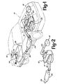
- Figure 1 is a perspective of an automotive vehicle having the particulate and exhaust gas emissions control.
- Figure 2 is a perspective of the particulate and exhaust gas emission control connected directly to the exhaust manifold of a diesel engine.
- Figure 3 is a cross section of the particulate trap.
- Figure 4 is an enlarged cross section of the filter element.
- Figure 5 is a transverse cross section of the filter element.
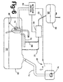
- Figure 6 is a schematic of a first embodiment of the metering mechanism having an electro-mechanical metering device.
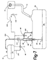
- Figure 7 is a schematic of a second embodiment of the metering mechanism having a hydraulically actuated piston metering device.
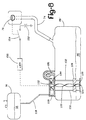
- Figure 8 is a schematic of a third embodiment of the metering mechanism having a hydro-mechanically driven vane type metering device.
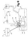
- Figure 9 is a schematic of a third embodiment of the metering mechanism having a hydro-mechanically driven peristaltic metering mechanism.
- FIG. 1 shows the diesel engine particulate and exhaust gas emission control system installed in an automotive vehicle 10, shown in phantom, having a diesel engine 12.
- Air is provided to the intake manifold 14 of the engine by means of a turbocharger 16 receiving ambient air through a filter 18 and an air intake conduit 20.
- the turbocharger 16 is also connected to the engine's exhaust manifold 22 and driven by the exhaust gases emitted from the engine.
- a particulate trap 24 is connected to the exhaust manifold 22, downstream of the turbocharger 16.
- the turbocharger 16 is an accessory which is not required for the operation of the diesel engine particulate and exhaust gas emission control system, and therefore, may be omitted as shown in Figure 2.
- the air intake conduit 20 is connected directly to the air intake manifold 14 and the particulate trap 24 is connected directly to the exhaust manifold 22.
- An exhaust or tailpipe 26 extends from the particulate trap 24 to the rear of the vehicle 10 as shown.
- Fuel for the diesel engine 12 is stored in a fuel tank 28 and is conducted to the engine in a conventional manner.
- An additive tank 30 is disposed adjacent or in close proximity to the fuel tank 28 and contains a fuel additive which is added to the diesel fuel in the fuel tank 28 by means of connecting line 32.
- the additive tank 28 is disposed in the trunk of the vehicle where it is readily accessible for refilling when necessary.
- a metering device 34 is attached to the connecting line 32 to provide a measured quantity of fuel additive to the fuel in the fuel tank 28. The measured quantity of the fuel additive is proportional to the quantity of fuel added each time fuel is added to (pumped into) the fuel tank 28.
- the fuel additive preferably consists a carbon ignition temperature depressing agent effective to promote oxidation of the soot (carbon particulates) collected by the particulate trap 24.
- the agent comprises a predetermined organometallic compound dissolved in an aerosol-promoting liquid carrier effective to form a fine mist with the organometallic compound and the fuel when sprayed (injected) into the cylinders of the engine to initiate internal combustion.
- the predetermined organometallic compound forms a reducible metal oxide as a result of the combustion process in the diesel engine which is co-deposited with the carbon particulate (soot) on the surface of the particulate trap 24.
- This metal oxide acts as a catalyst reducing the ignition temperature of the carbon particulate collected by the particulate trap to a temperature in the range from 250°C to 360°C (450° to 675°F).
- the aerosol-promoting liquid carrier has a boiling point in the range from 80° to 150°C and may be selected from a group of aerosol liquid carriers consisting of hexane, pentane, and toluene.
- the organometallic compound is ferrocene, a metal octoate or metal octoate complex with the metal selected from a group consisting of copper, nickel, and cerium.
- a copper octoate or a copper octoate complex promotes a lower ignition temperature for the carbon particulate collected on the surfaces of the particulate trap 24.
- copper octoates or a copper octoate complex in combination with nickel or cerium or ferrocene promotes ignition temperatures of the carbon particulates to within the temperature range of the particulate trap under various normal operating engine conditions of the diesel engine.
- Such organometallic compounds and ferrocene are readily soluble and stable in diesel fuel.
- the proportion of the organometallic compound to carrier in the fuel additive is preferably in the range from 1:2 to 1:10 and optimally the quantity of the fuel additive is such that 0.5 gm of the selected octoate or octoate complexes is added to each gallon of fuel.
- organometallic compounds used in the fuel additive are toxic to humans, animals or plants in their initial or reduced states.
- the particulate trap 24 consists of a metal housing or canister 36 enclosing a monolithic ceramic filter element 38.
- the canister 36 has an input collar 40 connectable to the exhaust manifold 22 of the diesel engine and an output collar 42 connectable to the tailpipe 26.
- the input of the particulate trap 24 may be connected to the output of a turbocharger 16 ( Figure 1) or it may be connected directly to the exhaust manifold 22 ( Figure 2).
- the filter element is composed of a permeable ceramic material, such as cordite.
- the monolithic filter element 38 has a honeycomb structure consisting of a plurality of parallel channels.
- the channels are divided into alternating inlet channels 44 and exit channels 46.
- the inlet channels 44 are open at an inlet end 48 of the filter element 38 and plugged at the exit end 50.
- exit channels 46 are plugged at the inlet end 48 and open at the exit end 50.
- the inlet and exit channels 44 and 46 are separated by thin porous longitudinal side walls 52 which permit the exhaust gases to pass from the inlet channels 44 to the exit channels 46 along their length.
- the inlet and exit channels 44 and 46 have a substantially rectangular cross-sectional shape as shown in Figure 5.
- the rectangular inlet and exit channels 44 and 46 are approximately eight to twelve inches long, and 2.1 mm (0.083 inches) wide.
- the length of the inlet and exit channels may range from 5 to 60 cm (2 to 24 inches) and their widths may vary from 1.25 to 3.75 mm (0.05 to 0.15 inches).
- the honeycombed monolithic element 38 provides a very large filtration surface area per unit volume significantly reducing the size of the particulate filter.
- the porous walls 52 separating the inlet and exit channels 44 and 46 are approximately 0.43 mm (0.017 inches) thick.
- the pores in the side walls 52 are small enough to effectively prevent the carbon particulate from passing therethrough so that a layer 54 of carbon particulate and the metal oxide generated by the heating of the organometallic compound in the engine's cylinders are collected on the internal surfaces of the inlet channels 44 as shown.
- a thin layer 56 of an oxidation catalyst is deposited on the internal surfaces of the exit channels 46.
- the oxidation catalyst may be platinum, palladium or a platinum-palladium alloy such as used in current automotive catalytic converters.
- platinum, palladium, and alloys thereof are catalysts which promote the oxidation of the hydrocarbons and carbon monoxide byproducts of the combustion of the fuel in the diesel engine 10 reducing the emissions of noxious and undesirable exhaust gases.
- the position of the oxidation catalyst in the exit channels 46 is highly effective for the removal of noxious and undesirable gases exhausted from the engine because they do not become poisoned or occluded by excessive layers of soot.
- the layer of oxidation catalyst 56 formed along the internal side walls of the exit channels also extends at least part way into the pores.
- the thickness of the layer of oxidation layer 56 is exaggerated for illustrative purposes only.
- this layer is composed of one or more layers of metal crystal platelets having a width in the range from 100 ⁇ to 400 ⁇ and a thickness of approximately 50 to 100 ⁇ and therefore, is approximately 100 ⁇ to 200 ⁇ thick and does not inhibit the passing of the exhaust gases through the pores of the ceramic filter element.
- the deposition of the oxidation catalyst in the pores provides a significant increase in its surface area providing a more intimate contact of the exhaust gases with the oxidation layer as the exhaust gases pass from the inlet channels 44 into the exit channels 46 and escape towards the exit end 50 of the filter element 38.
- the particulate trap may also include one or more exhaust gas dispersion members, such as dispersion member 58 disposed between the input collar 40 and the inlet end 48 of the filter element 38.
- the dispersion member 58 will have a plurality of slits or apertures which disperse the exhaust gases more uniformly across the inlet end of the filter element 38. In this manner, the carbon particulates carried by the exhaust gases are more uniformly distributed among the plurality of inlet channels of the filter element 38.
- the exhaust gases from the engine 10 are received through the input collar 40 and are uniformly dispersed by the dispersion element 58.
- the dispersion element 58 As the exhaust gases pass through the porous walls of the inlet channels 44 into the exit channels 46, the carbon particulates and the reducible metal oxide 54 resulting from the combustion in the engine of the fuel along with the fuel additive are filtered from the exhaust gases and form the layer of carbon particulates and metal oxide 54 on the internal surfaces of the inlet channels 44.
- the reducible metal oxide promotes the ignition of the deposited carbon particulates producing carbon dioxide and carbon monoxide gases which now pass through the walls of the inlet channels. In this manner, the deposited carbon particulates are reduced to a gas effectively cleaning the inlet channels.
- the gases produced as a result of the combustion of the fuel in the engine and the ignition of the carbon particulates captured by the filter element pass through the longitudinal walls of the filter element from the inlet channels 44 to the exit channels 46 where they react with the catalyst to burn up the excess hydrocarbons and oxidize the carbon monoxide. Because the catalyst is not poisoned or covered by soot, its catalytic action is greater than it would be in a standard unprotected catalytic converter.
- the ignition of the carbon particulate collected by the filter element 38 will occur repeatedly under normal operating conditions of the vehicle so that the back pressure caused by the carbon particulate collected by the filter element will normally be in the range from a back pressure caused by a clean filter element to less than twice the back pressure caused by the clean filter. Effectively, the particulate trap is self-cleaning and maintenance free.
- the organometallic additive 58 is stored in an additive tank 30.
- the additive tank 30 preferably holds two gallons of the organometallic additive 58 which quantity is sufficient for a passenger vehicle to be driven 120 000 km (75,000 miles) before servicing of the system and refiling the additive tank.
- a connecting line 62 connects the additive tank 30 to a metering device 60 which in response to an additive control 64 meters the desired quantity of the organometallic additive to the diesel fuel 66 stored in the fuel tank 28 of the vehicle.
- the metering device 60 may be an electrically actuated fluid pump or any other type of fluid metering device known in the art.
- the metered quantity of organometallic additive 58 is conducted to the fuel tank 28 by means of connecting line 68 and fuel return line 70.
- the organometallic additive may be conducted directly to the fuel tank 28 by a connecting line 72 as shown in phantom.
- Diesel fuel is added to the fuel tank 28 by means of a fill pipe 74 which conventionally is closed at the end opposite the fuel tank 28 by a removable cover such as fuel cap 76.
- a fuel level sensor 78 having a float 80 generates an electrical signal having a value corresponding to the quantity of diesel fuel 66 in the fuel tank 28.
- the metering control 64 is responsive to a change in the value of the electrical signal generated by the fuel level sensor 78 to actuate the metering device 60 to deliver to the fuel tank 28 the desired quantity of organometallic additive 58 proportional to the quantity of diesel fuel added to the fuel tank 28.
- the metering control 64 will contain averaging circuits which will render it non-responsive to changes in the fuel level in the vicinity of the float 80 due to the sloshing of the fuel during acceleration, deceleration or turning of the vehicle.
- the metering control 64 may be responsive to the actuation of a switch 82 (shown in phantom) when the fuel cap 76 is removed to add fuel to the fuel tank 28.
- Fuel to the engine is pumped from the fuel tank 28 via fuel line 84 in a conventional manner.
- the metering control 64 detects a change in the value of the electrical signal generated by the fuel level sensor 78 indicating a quantity of fuel has been added to the fuel tank 28, the metering control will add the desired quantity of organometallic additive to the quantity of fuel in the fuel tank 28 proportional to the quantity of fuel that has been added to maintain a desired ratio of the organometallic additive to the diesel fuel.
- the desired ratio is in the range from 0.04 to 0.132 grams of organometallic additive per litre of fuel.
- a volume amount of the additive/carrier mixture in the range of 2.10 to 13.2 ml is added for each litre of added fuel.
- the metering device 60 is a hydro-mechanical metering mechanism 84 having a cylinder 86 mounted to the top of the fuel tank 28 by means of a collar 94.
- a piston 88 is disposed in the cylinder 86 and connected to a float 92 by means of a piston rod 90.
- the float 92 floats on the surface of the diesel fuel 66 in the fuel tank 28 and displaces the piston 88 upwards when fuel is added to the fuel tank and displaces the piston downward when fuel is removed from the fuel tank 28 in a conventional manner.
- a normally open electro-mechanical valve 96 is disposed in the line 100 connecting the additive tank 30 to the input of the hydro-mechanical metering device 84 and a normally closed electro-mechanical valve 98 is connected to connecting line 102 leading from the outlet of the hydro-mechanical pump 84 to the fuel tank 28.
- a vent line 104 connects the top of the cylinder 86 back to the top of the additive tank 30 to remove any gas that may be trapped in the cylinder 86 between the piston and the top of the cylinder 86.
- a normally open electrical switch 106 provides electrical power from the vehicle's source of electrical power, such as battery 108 to the electro-mechanical valves 96 and 98 when the fuel cap 76 is removed from the end of the fill pipe 74.
- switch 106 closes actuating normally open valve 96 to close and actuating normally closed valve 98 to open.
- the float 92 will rise displacing the piston 88 upwardly.
- the upward displacement of the piston 88 will pump the organometallic additive contained in the cylinder 86 into the fuel tank through the now open normally closed valve 98.
- the activated normally open valve 96 prevents the organometallic additive from being pumped by piston 88 back into the additive tank 30.
- a check valve 110 may be included in the vent line 104.
- the check valve 110 will normally remain open under low pressure conditions to allow gases accumulated in the cylinder 86 to be vented to the additive tank but will close in response to the fluid pressure generated by the rising of the piston 88 in response to adding fuel to the fuel tank 28.
- the cross-sectional area defined by the internal diameter of the cylinder 86 is selected to be proportional to the cross-sectional area of the fuel tank 28 so that as fuel is added to the fuel tank 28, the quantity of organometallic additive pumped by the rising of piston 88 in the cylinder 86 will have the desired volumetric ratio of fuel additive to fuel.
- the metering device is a vane type metering device 112 of conventional design mounted to the top of the fuel tank 28.
- the vane type metering device 112 has an offset rotor 114 and a plurality of vanes 116.
- Organometallic additive 58 from the additive tank 30 is conducted to the inlet of the vane type metering device 112 by a connector line 118.
- the outlet of the vane type metering device 112 is connected directly to fuel tank 28 by a U-shaped channel 120.
- the offset rotor 114 of the vane type metering device is connected to one end of a spiral shaft 122.
- the other end of the spiral shaft 122 has an axle 124 rotatably received in a stationary base 126 adjacent to the bottom of the fuel tank 28.
- a float member 128 is guided by a pair of vertically oriented guide bars 130 and 132 connected between the vane pump 112 and the stationary base 126.
- the float member is slidably connected to the spiral shaft 122 in such a way that the vertical displacement of the float member 128 will rotate the spiral shaft 122 and the offset rotor 114 of the metering device.
- the spiral shaft 122 is preferably connected to the offset rotor 114 by means of a unidirectional clutch or coupling 134 which decouples the spiral shaft 122 from the offset rotor 114 when the spiral shaft is rotated in the opposite direction by the float member 128 descending as fuel is pumped from the fuel tank 28.
- the metering device 112 provides the required quantity of organometallic additive to the fuel tank 28 each time fuel is added.
- An electro-mechanical locking mechanism 156 may be used to inhibit the rotation of the spiral shaft 122 or the offset rotor 114 due to sloshing of the fuel in the fuel tank 28 due to acceleration, deceleration or turning when the fuel cap is attached to the fuel tank 28.
- the electro-mechanical locking mechanism 156 is energized to release the spiral shaft or offset rotor 114 by a switch 154 closed in response to the removal of the fuel cap.
- Switch 154 connects the vehicle's source of electrical power, illustrated by battery 152, to the locking mechanism 156 when the fuel cap is removed prior to pumping fuel into the fuel tank and disconnects the locking mechanism 156 from the battery 152 when the fuel cap is returned.
- the switch 154 may be actuated by opening the fuel cap access door 77 covering the fuel cap 76 when the vehicle is equipped with such a door.
- Figure 9 shows an alternate type of metering device for dispensing the required quantity of the organometallic additive to the diesel fuel in response to adding diesel fuel to the fuel tank.
- a peristaltic multiple lobe metering device 136 has a plurality of lobes 138 attached to a ratchet gear 140.
- the ratchet gear 140 is rotated by a rack 142 attached to a float 144.
- the rack 142 is biased against the ratchet gear 140 by a spring 146 so that the rack 142 will rotate the ratchet gear 140 in response to a vertical displacement of the float 144 as the gas tank 28 is being filled.
- the organometallic additive is conducted to the fuel tank 28 by means of a flexible tubing 148 which passes between the lobes 138 and an S-shaped backing plate 150.
- a flexible tubing 148 which passes between the lobes 138 and an S-shaped backing plate 150.
- rollers attached to the end of each lobe compress the flexible tubing 148 against the backing plate 150 dispensing a quantity of the organometallic additive into the fuel tank 28 as the lobes rotate proportional to the quantity of diesel fuel added.
- an electro-mechanical locking mechanism 156 may be used to inhibit the rotation of the ratchet gear 140 due to the sloshing of the fuel in the gas tank 28.
- the locking mechanism 156 is activated to release the ratchet gear 140 in response to the application of electrical power from the vehicle's source of electrical power, illustrated as battery 152, by the closing of switch 154.
- the switch 154 is closed in response to removing the fuel cap 76 from the fill pipe 74.
- the locking mechanism 156 permits the addition of the organometallic additive into the fuel tank only when the fuel cap 76 is removed to add fuel to the fuel tank.
Landscapes
- Engineering & Computer Science (AREA)
- Chemical & Material Sciences (AREA)
- Combustion & Propulsion (AREA)
- Oil, Petroleum & Natural Gas (AREA)
- Chemical Kinetics & Catalysis (AREA)
- Mechanical Engineering (AREA)
- General Engineering & Computer Science (AREA)
- Organic Chemistry (AREA)
- General Chemical & Material Sciences (AREA)
- Health & Medical Sciences (AREA)
- Sustainable Development (AREA)
- Sustainable Energy (AREA)
- Transportation (AREA)
- Life Sciences & Earth Sciences (AREA)
- Toxicology (AREA)
- Biomedical Technology (AREA)
- Environmental & Geological Engineering (AREA)
- Analytical Chemistry (AREA)
- Emergency Medicine (AREA)
- Processes For Solid Components From Exhaust (AREA)
- Exhaust Gas After Treatment (AREA)
- Exhaust Gas Treatment By Means Of Catalyst (AREA)
Claims (14)
- Un dispositif de contrôle des particules et des gaz d'échappement en provenance d'un véhicule automobile équipé d'un moteur diesel (12), d'un piège à particules (24) que l'on peut raccorder au collecteur de gaz d'échappement (22) dudit moteur diesel, un réservoir de carburant (28), un réservoir d'additif (30) pour le stockage de l'additif pour carburant utilisé pour abaisser la température d'inflammation des particules de carbone récoltées dans le piège à particules (24) et un dispositif (34) pour doser ledit additif pour carburant dans ledit réservoir de carburant (28) en fonction du carburant que l'on ajoute dans ledit réservoir de carburant, ledit dispositif de dosage ajoutant une certaine quantité dudit additif pour carburant à l'intérieur dudit réservoir de carburant proportionnellement à la quantité de carburant introduite de façon à conserver un rapport prédéterminé entre ledit additif pour carburant et ledit carburant à l'intérieur dudit réservoir,
caractérisé en ce que
ledit piège à particules (24) présente un grand nombre de canaux d'entrée et de sortie parallèles (44, 46) séparés par des parois poreuses disposées dans le sens de la longueur (52), lesdites parois poreuses disposées dans le sens de la longueur permettant aux gaz d'échappement de passer des dits canaux d'admission (44) aux dits canaux de sortie (46), lesdits canaux d'admission collectant sur leurs parois les particules de carbone contenues dans les gaz d'échappement et lesdits canaux de sortie (46) ayant sur leurs surfaces intérieures une couche (56) constituée par un matériau catalytique choisi à partir du platine, du palladium et des alliages de platine et de palladium de façon à favoriser l'oxydation du monoxyde de carbone et des hydrocarbures imbrûlés présents au sein des gaz d'échappement, ladite couche de matériau catalytique s'étendant à l'intérieur des pores desdites parois latérales poreuses disposées dans le sens de la longueur (52) de façon à augmenter la surface spécifique dudit catalyseur d'oxydation. - Un dispositif de contrôle tel que revendiqué dans la revendication 1, dans lequel ledit piège à particules est constitué d'une structure céramique poreuse en nid d'abeilles.
- Un dispositif de contrôle tel que revendiqué dans la revendication 2, dans lequel ledit piège à particules est constitué d'un structure céramique, monolithique et poreuse en nids d'abeilles.
- Un dispositif de contrôle tel que revendiqué dans l'une quelconque des revendications précédentes, dans lequel Ledit additif pour carburant est un composé organométallique dissout dans un véhicule liquide favorisant la formation des aérosols.
- Un dispositif de contrôle tel que revendiqué dans la revendication 4, dans lequel ledit composé organométallique est au moins constitué par un octoate métallique dont le métal est choisi dans le groupe formé par le cuivre, le nickel et le cérium.
- Un dispositif de contrôle tel que revendiqué dans la revendication 4 ou dans la revendication 5, dans lequel ledit véhicule liquide favorisant la formation d'aérosols est choisi dans le groupe formé par l'hexane, le pentane et le p-toluène.
- Un dispositif de contrôle tel que revendiqué dans l'une quelconque des revendications précédentes, dans lequel ledit véhicule automobile possède une trappe de fermeture 76 que l'on doit ouvrir si l'on veut ajouter du carburant dans ledit réservoir de carburant et dans lequel ledit dispositif de dosage (34) comprend :un système de détection d'ouverture de ladite trappe de fermeture qui doit être en position ouverte pour qu'un signale de remplissage soit envoyé;un dispositif (78, 80) pour détecter la quantité de carburant ajouté dans le réservoir de carburant et générer un signal décrivant la quantité de carburant;un dispositif de contrôle du dosage (64) permettant la génération d'un signal renseignant sur la quantité d'additif en réponse audit signal de remplissage et audit signal de quantité de carburant, ledit signal de quantité d'additif ayant une valeur proportionnelle à la quantité de carburant ajoutée audit réservoir de carburant; etun appareil de dosage (60) pour le dosage de ladite quantité d'additif pour carburant en provenance dudit réservoir d'additif vers ledit réservoir de carburant en réponse audit signal de quantité d'additif.
- Un dispositif de contrôle tel que revendiqué dans l'une quelconque des revendications 1 a 6, dans lequel ledit dispositif de dosage comprend :un appareil de dosage (84) composé d'un cylindre (86), d'un piston (88) placé à l'intérieur dudit cylindre et d'au moins un orifice;une vanne (96) normalement en position ouverte commandant l'écoulement dudit additif pour carburant en provenance dudit réservoir d'additif en direction dudit ou desdits orifices;une vanne (98) normalement en positon fermée raccordant ledit ou lesdits orifices audit réservoir de carburant;un dispositif (106) commandant ladite vanne (96) normalement en position ouverte pour qu'elle se mette en position fermée et ladite vanne (98) normalement en position fermée pour qu'elle se mette en position ouverte en réponse à l'ouverture dudit système de fermeture (76); etun flotteur (92) raccordé audit piston (88), ledit flotteur déplaçant ledit piston sur une distance proportionnelle à la quantité de carburant ajoutée à l'intérieur dudit réservoir de carburant, ledit déplacement dudit piston agit en ajoutant ladite quantité d'additif pour carburant à l'intérieur dudit réservoir pour carburant lorsque ladite vanne (96), normalement en position ouverte, est refermée et lorsque ladite vanne (98), normalement en position fermée est ouverte, de façon à conserver ledit rapport prédéterminé.
- Un dispositif de contrôle tel que revendiqué dans l'une quelconque des revendications 1 à 6, dans lequel ledit dispositif de dosage comprend :un appareil de dosage à ailettes (112) raccordé audit réservoir de carburant, ledit appareil de dosage à ailettes et disposant d'une ouverture d'admission raccordée audit réservoir d'additif, une ouverture de sortie raccordée audit réservoir de carburant, un rotor (114), et un ensemble d'ailettes (116) raccordées audit rotor;un axe spiralé (122) raccordé audit rotor; etun système de flotteurs (128) raccordé de façon coulissante audit axe spiralé, ledit système de flotteur entraînant la rotation dudit axe spiralé en réponse à l'addition de carburant dans ledit réservoir de carburant, ledit système de flotteur faisant tourner ledit axe spiralé et ledit rotor d'un angle proportionnel à la quantité de carburant ajoutée, faisant que ledit appareil de dosage à ailettes dose ladite quantité dudit additif pour carburant à l'intérieur dudit réservoir de carburant pour maintenir ledit rapport prédéterminé dudit additif pour carburant par rapport audit carburant à l'intérieur dudit réservoir de carburant.
- Un dispositif de contrôle tel que revendiqué dans la revendication 9, dans lequel ledit véhicule automobile comprend un système de fermeture (76) qui doit impérativement être ouvert si l'on veut rajouter du carburant à l'intérieur dudit réservoir de carburant, et dans lequel ledit dispositif de dosage comprend en outre :un mécanisme de verrouillage (156) qui à l'état verrouillé empêche la rotation dudit rotor et qui à l'état déverrouillé permet la rotation dudit rotor; etun dispositif (154) permettant de commander ledit mécanisme de verrouillage de façon qu'il se mette en position déverrouillée en réponse à ladite ouverture du système de fermeture (76).
- Un dispositif de contrôle tel que revendiqué dans la revendication 9 ou la revendication 10 dans lequel ledit système de dosage comprend en outre un embrayage unidirectionnel (134) raccordant ledit rotor (114) audit axe spiralé (122), ce qui permet audit axe spiralé de faire tourner ledit rotor dans un seul sens fixé à l'avance.
- Un dispositif de contrôle tel que revendiqué dans l'une quelconque des revendications 1 à 6, dans lequel ledit dispositif de dosage comprend :un appareil de dosage péristaltique (136) reliant ledit réservoir d'additif audit réservoir de carburant, ledit appareil de dosage péristaltique étant équipé d'un rotor (138) à cames ou lobes multiples;une roue à cliquets (140) reliée audit rotor à cames ou lobes multiples;un flotteur (144) placé à l'intérieur dudit réservoir de carburant; etune crémaillère (142) raccordant ledit flotteur à ladite roue à cliquets, ladite crémaillère faisant tourner ladite roue à cliquets dans un sens unique et fixé d'avance en réponse à l'addition de carburant à l'intérieur dudit réservoir de carburant, ladite rotation de ladite roue à cliquets entraînant ledit appareil de dosage péristaltique de façon à ce qu'il dose ladite quantité dudit additif pour carburant à partir dudit réservoir d'additif vers ledit réservoir de carburant pour maintenir ledit rapport fixé à l'avance entre ledit additif pour carburant et ledit carburant à l'intérieur dudit réservoir de carburant.
- Un dispositif de contrôle tel que revendiqué dans la revendication 12, dans lequel ledit véhicule automobile comprend un système de fermeture (76) qui doit être obligatoirement en position ouverte si l'on veut pouvoir ajouter du carburant à l'intérieur dudit réservoir de carburant, et dans lequel ledit dispositif de dosage comprend en outre :un mécanisme de verrouillage (156) qui, à l'état verrouillé, empêche le déclenchement dudit appareil de dosage péristaltique par ledit flotteur (144) et qui, en position déverrouillée, permet le déplacement dudit flotteur en réponse à l'addition de carburant à l'intérieur dudit réservoir de carburant, etun dispositif (154) de commande dudit mécanisme de verrouillage qui, à l'état déverrouillé, permet audit flotteur de commander ledit appareil de dosage péristaltique en réponse à l'ouverture dudit système de fermeture (75).
- Un dispositif de contrôle tel que revendiqué dans l'une quelconque des revendications précédentes, dans lequel ledit piège à particules possède une structure céramique poreuse et est placé, relativement audit collecteur de gaz d'échappement, à une distance fixée d'avance pour permettre auxdit gaz d'échappement de chauffer ladite structure céramique poreuse à l'intérieur d'une gamme de températures bien déterminée supérieures à la température minimale d'inflammation des particules de carbone collectées pour au moins un régime de fonctionnement dudit moteur diesel.
Priority Applications (1)
| Application Number | Priority Date | Filing Date | Title |
|---|---|---|---|
| EP96107633A EP0731256B1 (fr) | 1992-09-28 | 1993-09-08 | Elément filtrant pour la commande d'émission des gaz d'échappement des moteurs à combustion interne |
Applications Claiming Priority (2)
| Application Number | Priority Date | Filing Date | Title |
|---|---|---|---|
| US95227492A | 1992-09-28 | 1992-09-28 | |
| US952274 | 1992-09-28 |
Related Child Applications (2)
| Application Number | Title | Priority Date | Filing Date |
|---|---|---|---|
| EP96107633A Division EP0731256B1 (fr) | 1992-09-28 | 1993-09-08 | Elément filtrant pour la commande d'émission des gaz d'échappement des moteurs à combustion interne |
| EP96107633.8 Division-Into | 1993-09-08 |
Publications (3)
| Publication Number | Publication Date |
|---|---|
| EP0590814A2 EP0590814A2 (fr) | 1994-04-06 |
| EP0590814A3 EP0590814A3 (en) | 1994-06-08 |
| EP0590814B1 true EP0590814B1 (fr) | 1996-12-18 |
Family
ID=25492730
Family Applications (2)
| Application Number | Title | Priority Date | Filing Date |
|---|---|---|---|
| EP93307094A Expired - Lifetime EP0590814B1 (fr) | 1992-09-28 | 1993-09-08 | Système de contrÔle d'émission de particules et de gaz d'échappement |
| EP96107633A Expired - Lifetime EP0731256B1 (fr) | 1992-09-28 | 1993-09-08 | Elément filtrant pour la commande d'émission des gaz d'échappement des moteurs à combustion interne |
Family Applications After (1)
| Application Number | Title | Priority Date | Filing Date |
|---|---|---|---|
| EP96107633A Expired - Lifetime EP0731256B1 (fr) | 1992-09-28 | 1993-09-08 | Elément filtrant pour la commande d'émission des gaz d'échappement des moteurs à combustion interne |
Country Status (4)
| Country | Link |
|---|---|
| US (1) | US5758496A (fr) |
| EP (2) | EP0590814B1 (fr) |
| JP (1) | JPH06193427A (fr) |
| DE (2) | DE69306715T2 (fr) |
Families Citing this family (92)
| Publication number | Priority date | Publication date | Assignee | Title |
|---|---|---|---|---|
| US5492679A (en) * | 1993-03-08 | 1996-02-20 | General Motors Corporation | Zeolite/catalyst wall-flow monolith adsorber |
| FR2720441B1 (fr) * | 1994-05-25 | 1996-09-06 | Rhone Poulenc Chimie | Un procédé de filtration et de combustion de matières carbonées issues de moteur à combustion interne. |
| EP0737236A1 (fr) * | 1993-12-31 | 1996-10-16 | Rhone-Poulenc Chimie | Un procede de filtration et de combustion de matieres carbonees issues de moteur a combustion interne |
| EP0846151A1 (fr) * | 1995-04-24 | 1998-06-10 | The Associated Octel Company Limited | Amelioration de la combustion |
| JP3387290B2 (ja) * | 1995-10-02 | 2003-03-17 | トヨタ自動車株式会社 | 排ガス浄化用フィルター |
| DE19805311B4 (de) * | 1997-02-18 | 2010-06-10 | Walbro Corp., Cass City | Vorrichtung und Verfahren zur Zugabe von Kraftstoffadditiven |
| TW509719B (en) * | 1997-04-17 | 2002-11-11 | Clean Diesel Tech Inc | Method for reducing emissions from a diesel engine |
| FR2771449B1 (fr) * | 1997-11-24 | 2000-02-04 | Ecia Equip Composants Ind Auto | Procede et dispositif de regeneration d'un filtre a particules |
| US6013599A (en) | 1998-07-15 | 2000-01-11 | Redem Corporation | Self-regenerating diesel exhaust particulate filter and material |
| JP2000167329A (ja) | 1998-09-30 | 2000-06-20 | Ibiden Co Ltd | 排気ガス浄化装置の再生システム |
| DE19904736A1 (de) * | 1999-02-05 | 2000-08-10 | Volkswagen Ag | Brennkraftmaschine mit einer Versorgungseinrichtung für ein Verbrennungsmedium |
| FR2789910B1 (fr) * | 1999-02-24 | 2004-07-09 | Renault | Procede de regeneration assistee de filtre a particules par apport de solution contenant des composes hydroxyles |
| AU2451200A (en) * | 1999-02-26 | 2000-09-14 | Johnson Matthey Public Limited Company | Monolithic catalyst/filter apparatus |
| FR2790223B1 (fr) * | 1999-02-26 | 2001-05-11 | Peugeot Citroen Automobiles Sa | Procede et dispositif d'introduction automatique d'un additif dans le reservoir de carburant d'un vehicule automobile |
| FR2791087A1 (fr) * | 1999-03-18 | 2000-09-22 | Daniel Biancotto | Collecteur d'echappement avec filtration des particules, echangeur de temperature et pare-flammes |
| FR2792036B1 (fr) * | 1999-04-06 | 2002-06-07 | Peugeot Citroen Automobiles Sa | Systeme d'aide a la regeneration d'un filtre a particules integre dans une ligne d'echappement d'un moteur diesel notamment de vehicule automobile |
| DE19921974A1 (de) * | 1999-05-12 | 2000-11-16 | Volkswagen Ag | Vorrichtung zum Reduzieren von schädlichen Bestandteilen im Abgas einer Brennkraftmaschine, insbesondere einer Diesel-Brennkraftmaschine |
| JP2001073742A (ja) * | 1999-06-29 | 2001-03-21 | Sumitomo Electric Ind Ltd | ディーゼルエンジン用パティキュレートトラップ |
| GB9919013D0 (en) | 1999-08-13 | 1999-10-13 | Johnson Matthey Plc | Reactor |
| US6428755B1 (en) | 1999-10-04 | 2002-08-06 | Ford Global Technologies, Inc. | Catalyst assembly for an exhaust gas system |
| JP2001221038A (ja) | 1999-12-13 | 2001-08-17 | Ford Global Technol Inc | 消音形排気コンバーター |
| US6276310B1 (en) | 2000-01-07 | 2001-08-21 | Ford Global Technologies, Inc. | Fuel additive dosing method and system for onboard vehicle use |
| FR2804175B1 (fr) * | 2000-01-20 | 2002-04-12 | Peugeot Citroen Automobiles Sa | Systeme d'aide a la regeneration d'un filtre a particules integre dans une ligne d'echappement d'un moteur diesel de vehicule automobile |
| FR2804169B1 (fr) * | 2000-01-20 | 2002-04-12 | Peugeot Citroen Automobiles Sa | Systeme d'aide a la regeneration d'un filtre a particules integre dans une ligne d'echappement d'un moteur diesel de vehicule automobile |
| FR2805002B1 (fr) * | 2000-02-16 | 2002-05-17 | Coutier Moulage Gen Ind | Dispositif d'injection d'un additif liquide dans un carburant contenu dans le circuit d'alimentation d'un moteur a combustion interne d'un vehicule |
| US6606856B1 (en) * | 2000-03-03 | 2003-08-19 | The Lubrizol Corporation | Process for reducing pollutants from the exhaust of a diesel engine |
| FR2807472B1 (fr) * | 2000-04-07 | 2002-10-25 | Peugeot Citroen Automobiles Sa | Systeme d'aide a la regeneration d'un filtre a particules integre dans une ligne d'echappement d'un moteur diesel de vehicule automobile |
| JP4742405B2 (ja) * | 2000-06-28 | 2011-08-10 | トヨタ自動車株式会社 | 燃料改質装置 |
| DE10035544B4 (de) * | 2000-07-21 | 2012-01-05 | Daimler Ag | Filteranordnung für eine Abgasreinigungsanlage |
| EP1328343A1 (fr) * | 2000-09-29 | 2003-07-23 | OMG AG & Co. KG | Filtre catalytique de particules de suie et utilisation de celui-ci afin de traiter des gaz d'echappement pauvres |
| DE10048511A1 (de) * | 2000-09-29 | 2002-04-18 | Omg Ag & Co Kg | Verfahren zur Verminderung von Kohlenmonoxid, Kohlenwasserstoffen und Partikel im mageren Abgas von Verbrennungsmotoren |
| US6629407B2 (en) * | 2000-12-12 | 2003-10-07 | Ethyl Corporation | Lean burn emissions system protectant composition and method |
| WO2002077424A1 (fr) * | 2001-03-22 | 2002-10-03 | Ibiden Co., Ltd. | Appareil de purification de gaz d'echappement |
| US7723257B2 (en) * | 2001-10-10 | 2010-05-25 | Dominique Bosteels | Process for the catalytic control of radial reaction |
| US7482303B2 (en) * | 2001-10-10 | 2009-01-27 | Dominique Bosteels | Catalytic burning reaction |
| FR2831492B1 (fr) * | 2001-10-30 | 2004-01-16 | Renault | Procede d'injection directe d'additif pour carburant de moteur a combustion interne |
| JP3649188B2 (ja) * | 2002-01-16 | 2005-05-18 | トヨタ自動車株式会社 | 排気浄化装置付き内燃機関 |
| DE10205380A1 (de) * | 2002-02-09 | 2003-08-21 | Daimler Chrysler Ag | Verfahren sowie Vorrichtung zur Behandlung von Dieselabgas |
| DE10214343A1 (de) * | 2002-03-28 | 2003-10-09 | Omg Ag & Co Kg | Partikelfilter mit einer katalytisch aktiven Beschichtung zur Beschleunigung der Verbrennung der auf dem Filter gesammelten Rußpartikel während einer Regenerationsphase |
| US20060021335A1 (en) * | 2004-07-29 | 2006-02-02 | Caterpillar, Inc. | Exhaust treatment system having particulate filters |
| DE10223148A1 (de) * | 2002-05-16 | 2003-11-27 | Ego Elektro Geraetebau Gmbh | Partikelfilter mit einer elektrischen Heizung |
| US20030226312A1 (en) * | 2002-06-07 | 2003-12-11 | Roos Joseph W. | Aqueous additives in hydrocarbonaceous fuel combustion systems |
| DE10229483A1 (de) * | 2002-07-01 | 2004-03-04 | Volkswagen Ag | Dosiereinrichtung und Verfahren zum Zuführen von Additiv zu einem Kraftstoff |
| JP4222599B2 (ja) * | 2002-10-10 | 2009-02-12 | 日本碍子株式会社 | ハニカム構造体及びその製造方法並びに当該ハニカム構造体を用いた排ガス浄化システム |
| US6971337B2 (en) | 2002-10-16 | 2005-12-06 | Ethyl Corporation | Emissions control system for diesel fuel combustion after treatment system |
| US20040074140A1 (en) * | 2002-10-16 | 2004-04-22 | Guinther Gregory H. | Method of enhancing the operation of a diesel fuel combustion after treatment system |
| FR2846713B1 (fr) | 2002-11-04 | 2006-03-10 | Marwal Systems | Dispositif de dosage d'additif pour carburant sur vehicule automobile |
| FR2848267B1 (fr) * | 2002-12-06 | 2006-11-24 | Peugeot Citroen Automobiles Sa | Systeme d'ajout d'un additif dans un carburant destine a un moteur de vehicule automobile |
| EP1581727B1 (fr) * | 2003-01-07 | 2010-11-10 | Peugeot Citroën Automobiles S.A. | Systeme d aide a la regeneration d un filtre a particul es d une ligne d echappement d un moteur diesel |
| FR2849671B1 (fr) * | 2003-01-07 | 2006-12-08 | Peugeot Citroen Automobiles Sa | Filtre a particules pour ligne d'echappement et ligne d'echappement, systeme d'aide a la regeneration et procede de traitement des gaz d'echappement l'utilisant |
| GB0304939D0 (en) * | 2003-03-05 | 2003-04-09 | Johnson Matthey Plc | Light-duty diesel engine and a particulate filter therefor |
| US6892531B2 (en) | 2003-04-02 | 2005-05-17 | Julius J. Rim | System for and methods of operating diesel engines to reduce harmful exhaust emissions and to improve engine lubrication |
| US20040231320A1 (en) * | 2003-05-22 | 2004-11-25 | Johnson Randall J. | Apparatus for reducing particulate emissions |
| DE10323385B4 (de) * | 2003-05-23 | 2006-02-02 | Daimlerchrysler Ag | Abgasreinigungsanlage für eine Brennkraftmaschine |
| US20050011413A1 (en) * | 2003-07-18 | 2005-01-20 | Roos Joseph W. | Lowering the amount of carbon in fly ash from burning coal by a manganese additive to the coal |
| US20050016057A1 (en) * | 2003-07-21 | 2005-01-27 | Factor Stephen A. | Simultaneous reduction in NOx and carbon in ash from using manganese in coal burners |
| FR2858355B1 (fr) * | 2003-07-31 | 2005-10-28 | Peugeot Citroen Automobiles Sa | Procede et dispositif de depollution des gaz d'echappement d'un moteur a combustion interne |
| US7101493B2 (en) * | 2003-08-28 | 2006-09-05 | Afton Chemical Corporation | Method and composition for suppressing coal dust |
| US7332001B2 (en) * | 2003-10-02 | 2008-02-19 | Afton Chemical Corporation | Method of enhancing the operation of diesel fuel combustion systems |
| US20050091913A1 (en) * | 2003-10-29 | 2005-05-05 | Aradi Allen A. | Method for reducing combustion chamber deposit flaking |
| DE10357120B4 (de) * | 2003-12-06 | 2006-06-01 | Daimlerchrysler Ag | Kraftfahrzeug mit Abgasreinigungsanlage und Betriebsverfahren hierfür sowie Abgasreinigungsanlage für ein Kraftfahrzeug |
| FR2872212B1 (fr) * | 2004-06-23 | 2006-11-03 | Peugeot Citroen Automobiles Sa | Systeme d'evaluation de l'etat de charge de moyens de depollution d'une ligne d'echappement |
| KR20070087121A (ko) * | 2004-06-30 | 2007-08-27 | 이비덴 가부시키가이샤 | 배기가스 정화 장치 |
| JP4907860B2 (ja) | 2004-11-11 | 2012-04-04 | 株式会社キャタラー | フィルタ触媒 |
| FR2879654B1 (fr) * | 2004-12-20 | 2010-04-30 | Inst Francais Du Petrole | Procede de regeneration de filtre a particules avec dispositif a combustion catalytique et installation de filtration utilisant un tel procede |
| US20060229198A1 (en) * | 2005-04-08 | 2006-10-12 | Mccarthy Stephen J | Noble metal alloy formation method to improve stability |
| US7698887B2 (en) * | 2005-06-17 | 2010-04-20 | Emcon Technologies Llc | Method and apparatus for determining local emissions loading of emissions trap |
| US7628835B2 (en) * | 2005-09-08 | 2009-12-08 | Honda Motor Co., Ltd. | Structure for holding fixing screws |
| DE102005047598A1 (de) * | 2005-10-05 | 2007-04-12 | Robert Bosch Gmbh | Filterelement und Filter zur Abgasnachbehandlung |
| US20070095053A1 (en) * | 2005-10-31 | 2007-05-03 | Arvin Technologies, Inc. | Method and apparatus for emissions trap regeneration |
| JP4270224B2 (ja) | 2005-11-09 | 2009-05-27 | トヨタ自動車株式会社 | 内燃機関の排気浄化装置 |
| CN101330961A (zh) * | 2005-12-16 | 2008-12-24 | 康宁股份有限公司 | 低压降的涂覆的柴油机废气过滤器 |
| US20070199310A1 (en) * | 2006-02-24 | 2007-08-30 | Eaton Corporation | Particulate trap regeneration system and method |
| US7726265B2 (en) * | 2006-03-10 | 2010-06-01 | Ethanol Boosting Systems, Llc | Fuel tank system for direct ethanol injection octane boosted gasoline engine |
| CA2652241A1 (fr) * | 2006-05-18 | 2007-11-29 | Clean Diesel Technologies, Inc. | Ameliorations dans le controle de particules derivees de moteur diesel |
| US7669409B2 (en) * | 2006-10-31 | 2010-03-02 | Caterpillar Inc. | Selective oxidation catalyst injection based on temperature |
| US20080127638A1 (en) * | 2006-12-01 | 2008-06-05 | Marius Vaarkamp | Emission Treatment Systems and Methods |
| US8800268B2 (en) * | 2006-12-01 | 2014-08-12 | Basf Corporation | Zone coated filter, emission treatment systems and methods |
| WO2008077204A2 (fr) * | 2006-12-22 | 2008-07-03 | Dominique Bosteels | Procédé de combustion catalytique à étape de régénération |
| FR2913431B1 (fr) * | 2007-03-06 | 2009-04-24 | Rhodia Recherches & Tech | Procede de fonctionnement d'un moteur diesel en vue de faciliter la regeneration d'un filtre a particules sur la ligne d'echappement |
| US7650747B2 (en) * | 2007-03-28 | 2010-01-26 | Gm Global Technology Operations, Inc. | Method and apparatus for exhaust gas purifying using hydrocarbon-selective catalytic reduction |
| US8056671B2 (en) * | 2007-10-12 | 2011-11-15 | Mazda Motor Corporation | Exhaust-gas purification device disposition structure of vehicle |
| KR100882665B1 (ko) | 2007-11-20 | 2009-02-06 | 현대자동차주식회사 | 매연 여과장치 |
| US9194272B2 (en) * | 2008-12-02 | 2015-11-24 | Caterpillar Inc. | Power system |
| GB0903262D0 (en) * | 2009-02-26 | 2009-04-08 | Johnson Matthey Plc | Filter |
| US8413431B2 (en) * | 2009-06-30 | 2013-04-09 | Eaton Corporation | Tank assembly |
| JP5408184B2 (ja) * | 2011-05-12 | 2014-02-05 | 三菱自動車工業株式会社 | 車両用添加剤タンクの配置構造 |
| CN103411549A (zh) * | 2013-08-30 | 2013-11-27 | 无锡凯睿传感技术有限公司 | 一种蜂窝陶瓷的检测装置 |
| CN103453938A (zh) * | 2013-08-30 | 2013-12-18 | 无锡凯睿传感技术有限公司 | 催化剂载体的检测装置及检测系统 |
| US10202929B1 (en) * | 2014-09-22 | 2019-02-12 | National Technology & Engineering Solutions Of Sandia, Llc | Additive-mixing fuel-injection system for internal combustion engines |
| MX2018014251A (es) * | 2016-05-17 | 2019-08-16 | Corning Inc | Filtros de cerámica porosa y métodos para filtrar. |
| GB2570450B (en) * | 2018-01-24 | 2020-09-02 | Jaguar Land Rover Ltd | Particulate filter with a particulate matter regeneration catalyst provided only on outlet channels |
Family Cites Families (26)
| Publication number | Priority date | Publication date | Assignee | Title |
|---|---|---|---|---|
| JPS56148607A (en) * | 1980-04-18 | 1981-11-18 | Enukoa:Kk | Exhaust gas filter for diesel engine |
| DE3101026A1 (de) * | 1981-01-15 | 1982-08-26 | Engelhard Kali-Chemie Autocat Gmbh, 3000 Hannover | Bifunktionaler filter zur behandlung von abgasen |
| DE3217357C2 (de) * | 1982-05-08 | 1987-03-12 | Fa. J. Eberspächer, 7300 Esslingen | Einrichtung zur Verminderung des Rußanteils im Abgas von Brennkraftmaschinen |
| JPS60108516A (ja) * | 1983-11-15 | 1985-06-14 | Mitsubishi Motors Corp | ディ−ゼルエンジンのパティキュレ−ト捕集フィルタ再生装置 |
| US4544388A (en) * | 1983-12-27 | 1985-10-01 | Ford Motor Company | Apparatus for periodically oxidizing particulates collected from exhaust gases |
| DE3376490D1 (fr) * | 1983-12-27 | 1988-06-09 | Ford Motor Company Limited | |
| US5100632A (en) * | 1984-04-23 | 1992-03-31 | Engelhard Corporation | Catalyzed diesel exhaust particulate filter |
| US4596277A (en) * | 1984-11-01 | 1986-06-24 | Stanadyne, Inc. | Additive metering system |
| US4728503A (en) * | 1984-11-02 | 1988-03-01 | Mitsubishi Jukogyo Kabushiki Kaisha | Filter medium for treating an exhaust gas |
| JPS61129016A (ja) * | 1984-11-28 | 1986-06-17 | Kiyataraa Kogyo Kk | ハニカム型パティキュレート捕集用フイルタの製造方法 |
| US4670020A (en) * | 1984-12-24 | 1987-06-02 | Ford Motor Company | Carbon ignition temperature depressing agent and method of regenerating an automotive particulate trap utilizing said agent |
| US4655037A (en) * | 1984-12-24 | 1987-04-07 | Ford Motor Company | Carbon ignition temperature depressing agent and method of regenerating an automotive particulate trap utilizing said agent |
| US4621593A (en) * | 1984-12-24 | 1986-11-11 | Ford Motor Company | Automotive dispensing apparatus for fuel additive |
| JPS63185425A (ja) * | 1987-01-28 | 1988-08-01 | Ngk Insulators Ltd | 排ガス浄化用セラミツクハニカムフイルタ |
| US4759918A (en) * | 1987-04-16 | 1988-07-26 | Allied-Signal Inc. | Process for the reduction of the ignition temperature of diesel soot |
| US5104627A (en) * | 1988-12-19 | 1992-04-14 | Usui Kokusai Sangyo Kabushiki Kaisha | Exhaust gas cleaning apparatus |
| JPH02110223U (fr) * | 1989-02-17 | 1990-09-04 | ||
| DE3923985C1 (fr) * | 1989-07-20 | 1990-06-28 | Daimler-Benz Aktiengesellschaft, 7000 Stuttgart, De | |
| DE3937809A1 (de) * | 1989-11-14 | 1991-05-16 | Schwaebische Huettenwerke Gmbh | Filter zum abscheiden von verunreinigungen |
| US5094074A (en) * | 1990-02-23 | 1992-03-10 | Nissan Motor Co., Ltd. | Catalytic converter with metallic carrier and method for producing same |
| US5402639A (en) * | 1990-07-02 | 1995-04-04 | Fleck; Carl M. | Device for cleaning exhaust gases |
| DE4022321A1 (de) * | 1990-07-13 | 1992-01-16 | Schwaebische Huettenwerke Gmbh | Filter |
| DE4028253C1 (en) * | 1990-09-06 | 1991-07-18 | Mercedes-Benz Aktiengesellschaft, 7000 Stuttgart, De | Additive feed for vehicle fuel tank - has piston controlled by tank float riding in cylinder to dispense additive |
| DE4133337A1 (de) * | 1990-10-08 | 1992-04-09 | Riken Kk | Abgasreiniger und verfahren zum reinigen von abgasen |
| FR2668203A1 (fr) * | 1990-10-23 | 1992-04-24 | Peugeot | Procede et dispositif d'introduction automatique d'un additif dans le reservoir de carburant d'un vehicule automobile et leur utilisation dans le cas d'un vehicule a moteur diesel. |
| US5248481A (en) * | 1992-05-11 | 1993-09-28 | Minnesota Mining And Manufacturing Company | Diesel particulate trap of perforated tubes having laterally offset cross-wound wraps of inorganic yarn |
-
1993
- 1993-09-08 EP EP93307094A patent/EP0590814B1/fr not_active Expired - Lifetime
- 1993-09-08 DE DE69306715T patent/DE69306715T2/de not_active Expired - Fee Related
- 1993-09-08 EP EP96107633A patent/EP0731256B1/fr not_active Expired - Lifetime
- 1993-09-08 DE DE69328202T patent/DE69328202T2/de not_active Expired - Fee Related
- 1993-09-27 JP JP5239504A patent/JPH06193427A/ja active Pending
-
1996
- 1996-02-20 US US08/603,511 patent/US5758496A/en not_active Expired - Fee Related
Also Published As
| Publication number | Publication date |
|---|---|
| EP0731256B1 (fr) | 2000-03-22 |
| DE69328202T2 (de) | 2000-07-20 |
| EP0590814A3 (en) | 1994-06-08 |
| JPH06193427A (ja) | 1994-07-12 |
| EP0731256A3 (fr) | 1996-11-27 |
| DE69306715T2 (de) | 1997-04-30 |
| EP0731256A2 (fr) | 1996-09-11 |
| EP0590814A2 (fr) | 1994-04-06 |
| DE69328202D1 (de) | 2000-04-27 |
| DE69306715D1 (de) | 1997-01-30 |
| US5758496A (en) | 1998-06-02 |
Similar Documents
| Publication | Publication Date | Title |
|---|---|---|
| US5758496A (en) | Particulate and exhaust gas emission control system | |
| US7093428B2 (en) | Exhaust system and method of thermal management | |
| Kummer | Catalysts for automobile emission control | |
| CN101985893B (zh) | 排气处理系统 | |
| CN101219339B (zh) | 有选择地还原废气供给流中的NOx的方法和装置 | |
| US4621593A (en) | Automotive dispensing apparatus for fuel additive | |
| Khair | A review of diesel particulate filter technologies | |
| JP4365118B2 (ja) | 複数の燃料で内燃機関を運転するための方法及び装置 | |
| US7240482B2 (en) | System for minimizing the impact of poisoning of automotive exhaust aftertreatment systems | |
| CN105765188B (zh) | 用于经催化基材的车载诊断系统和诊断方法 | |
| US20060080953A1 (en) | Method for regenerating a particle trap and exhaust system | |
| EP1128895A1 (fr) | Procede et dispositif de traitement de gaz d'echappement | |
| US20020038542A1 (en) | Hydrogen-containing gas producing system and exhaust gas purifying system using same | |
| US20120067026A1 (en) | Exhaust Gas Treatment System for an Internal Combustion Engine | |
| US8783022B2 (en) | Retrofit aftertreatment system for treating diesel exhaust | |
| JP2002530578A (ja) | ディーゼル機関からの微粒子放出を軽減するための触媒作用をもつ微粒子酸化部材およびその方法 | |
| EP3639908A1 (fr) | Système de purification de gaz d'échappement pour moteur essence | |
| KR20110025133A (ko) | 배기가스 정화 장치 | |
| Twigg | Controlling automotive exhaust emissions: Successes and underlying science | |
| US8484952B2 (en) | Device for purification of exhaust gas | |
| EP1392960B1 (fr) | Procede de dosage d'un additif au carburant | |
| CA1165247A (fr) | Epuration des gas d'echappement | |
| Gandhi et al. | Deactivation of three-way and oxidation catalyst dual bed emission control systems: catalyst post mortem analyses from methanol-fueled vehicles | |
| KR960003793B1 (ko) | 디젤차량 입자상물질 제거용 촉매체 및 이의 제조방법 | |
| WO2009137110A1 (fr) | Traitement de l'échappement d'un moteur à combustion interne en utilisant des matériaux en fibres de céramique immobilisées |
Legal Events
| Date | Code | Title | Description |
|---|---|---|---|
| PUAI | Public reference made under article 153(3) epc to a published international application that has entered the european phase |
Free format text: ORIGINAL CODE: 0009012 |
|
| AK | Designated contracting states |
Kind code of ref document: A2 Designated state(s): DE FR GB |
|
| PUAL | Search report despatched |
Free format text: ORIGINAL CODE: 0009013 |
|
| AK | Designated contracting states |
Kind code of ref document: A3 Designated state(s): DE FR GB |
|
| 17P | Request for examination filed |
Effective date: 19941121 |
|
| 17Q | First examination report despatched |
Effective date: 19950516 |
|
| GRAH | Despatch of communication of intention to grant a patent |
Free format text: ORIGINAL CODE: EPIDOS IGRA |
|
| GRAH | Despatch of communication of intention to grant a patent |
Free format text: ORIGINAL CODE: EPIDOS IGRA |
|
| GRAA | (expected) grant |
Free format text: ORIGINAL CODE: 0009210 |
|
| AK | Designated contracting states |
Kind code of ref document: B1 Designated state(s): DE FR GB |
|
| DX | Miscellaneous (deleted) | ||
| ET | Fr: translation filed | ||
| REF | Corresponds to: |
Ref document number: 69306715 Country of ref document: DE Date of ref document: 19970130 |
|
| PLBE | No opposition filed within time limit |
Free format text: ORIGINAL CODE: 0009261 |
|
| STAA | Information on the status of an ep patent application or granted ep patent |
Free format text: STATUS: NO OPPOSITION FILED WITHIN TIME LIMIT |
|
| 26N | No opposition filed | ||
| REG | Reference to a national code |
Ref country code: FR Ref legal event code: TP Ref country code: FR Ref legal event code: CD |
|
| REG | Reference to a national code |
Ref country code: GB Ref legal event code: IF02 |
|
| REG | Reference to a national code |
Ref country code: GB Ref legal event code: 746 Effective date: 20050112 |
|
| REG | Reference to a national code |
Ref country code: FR Ref legal event code: CD Ref country code: FR Ref legal event code: CA |
|
| PGFP | Annual fee paid to national office [announced via postgrant information from national office to epo] |
Ref country code: GB Payment date: 20060804 Year of fee payment: 14 |
|
| PGFP | Annual fee paid to national office [announced via postgrant information from national office to epo] |
Ref country code: FR Payment date: 20060906 Year of fee payment: 14 |
|
| PGFP | Annual fee paid to national office [announced via postgrant information from national office to epo] |
Ref country code: DE Payment date: 20060929 Year of fee payment: 14 |
|
| GBPC | Gb: european patent ceased through non-payment of renewal fee |
Effective date: 20070908 |
|
| PG25 | Lapsed in a contracting state [announced via postgrant information from national office to epo] |
Ref country code: DE Free format text: LAPSE BECAUSE OF NON-PAYMENT OF DUE FEES Effective date: 20080401 |
|
| REG | Reference to a national code |
Ref country code: FR Ref legal event code: ST Effective date: 20080531 |
|
| PG25 | Lapsed in a contracting state [announced via postgrant information from national office to epo] |
Ref country code: FR Free format text: LAPSE BECAUSE OF NON-PAYMENT OF DUE FEES Effective date: 20071001 |
|
| PG25 | Lapsed in a contracting state [announced via postgrant information from national office to epo] |
Ref country code: GB Free format text: LAPSE BECAUSE OF NON-PAYMENT OF DUE FEES Effective date: 20070908 |