EP0590821B1 - Kraftstoffversorgungssystem für Brennkraftmaschine - Google Patents
Kraftstoffversorgungssystem für Brennkraftmaschine Download PDFInfo
- Publication number
- EP0590821B1 EP0590821B1 EP93307195A EP93307195A EP0590821B1 EP 0590821 B1 EP0590821 B1 EP 0590821B1 EP 93307195 A EP93307195 A EP 93307195A EP 93307195 A EP93307195 A EP 93307195A EP 0590821 B1 EP0590821 B1 EP 0590821B1
- Authority
- EP
- European Patent Office
- Prior art keywords
- fuel
- tank
- engine
- pump
- outlet port
- Prior art date
- Legal status (The legal status is an assumption and is not a legal conclusion. Google has not performed a legal analysis and makes no representation as to the accuracy of the status listed.)
- Expired - Lifetime
Links
- 239000000446 fuel Substances 0.000 title claims description 113
- 238000002485 combustion reaction Methods 0.000 title claims description 6
- 239000002828 fuel tank Substances 0.000 claims description 13
- 230000003134 recirculating effect Effects 0.000 claims description 7
- 238000010438 heat treatment Methods 0.000 claims description 4
- 239000004449 solid propellant Substances 0.000 claims description 3
- 230000008901 benefit Effects 0.000 description 2
- 230000015572 biosynthetic process Effects 0.000 description 2
- 239000013078 crystal Substances 0.000 description 2
- 239000002283 diesel fuel Substances 0.000 description 2
- 230000006835 compression Effects 0.000 description 1
- 238000007906 compression Methods 0.000 description 1
- 239000003502 gasoline Substances 0.000 description 1
- 238000009434 installation Methods 0.000 description 1
- 239000012188 paraffin wax Substances 0.000 description 1
- 238000009428 plumbing Methods 0.000 description 1
- 210000001364 upper extremity Anatomy 0.000 description 1
- 239000001993 wax Substances 0.000 description 1
- 238000004018 waxing Methods 0.000 description 1
Images
Classifications
-
- F—MECHANICAL ENGINEERING; LIGHTING; HEATING; WEAPONS; BLASTING
- F02—COMBUSTION ENGINES; HOT-GAS OR COMBUSTION-PRODUCT ENGINE PLANTS
- F02M—SUPPLYING COMBUSTION ENGINES IN GENERAL WITH COMBUSTIBLE MIXTURES OR CONSTITUENTS THEREOF
- F02M37/00—Apparatus or systems for feeding liquid fuel from storage containers to carburettors or fuel-injection apparatus; Arrangements for purifying liquid fuel specially adapted for, or arranged on, internal-combustion engines
- F02M37/0047—Layout or arrangement of systems for feeding fuel
- F02M37/0052—Details on the fuel return circuit; Arrangement of pressure regulators
-
- F—MECHANICAL ENGINEERING; LIGHTING; HEATING; WEAPONS; BLASTING
- F02—COMBUSTION ENGINES; HOT-GAS OR COMBUSTION-PRODUCT ENGINE PLANTS
- F02M—SUPPLYING COMBUSTION ENGINES IN GENERAL WITH COMBUSTIBLE MIXTURES OR CONSTITUENTS THEREOF
- F02M37/00—Apparatus or systems for feeding liquid fuel from storage containers to carburettors or fuel-injection apparatus; Arrangements for purifying liquid fuel specially adapted for, or arranged on, internal-combustion engines
- F02M37/20—Apparatus or systems for feeding liquid fuel from storage containers to carburettors or fuel-injection apparatus; Arrangements for purifying liquid fuel specially adapted for, or arranged on, internal-combustion engines characterised by means for preventing vapour lock
Definitions
- the invention relates to a fuel supply system for an internal combustion engine.
- U.S. 4,989,572 to Giacomazzi et al. discloses a fuel plumbing arrangement intended to mitigate heat buildup in a fuel tank by returning the recirculated fuel to an in-tank reservoir containing the vehicle's fuel pump.
- a system according to the present invention may be operated so as to eliminate any heating of the fuel in the fuel tank due to recirculation of fuel. Nevertheless, if heating is desired so as to avoid waxing on fuel filters during operation at very low ambient temperatures, or for other reasons, a system according to the present invention may be used to control the fraction of the total fuel flow which is returned to the tank. It is an advantage of the present invention that fuel tank temperature may be controlled by allowing some, all, or none of the fuel being returned from the engine to enter the fuel tank.
- a fuel supply system according to the preamble of claim 1 is known from EP-A-0 411 964.
- a recirculating fuel supply system for an internal combustion engine comprising:
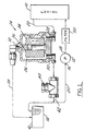
- Figure 1 contains a schematic representation of a fuel supply system for an internal combustion engine embodying the present invention.
- an engine 10 is supplied with fuel from a tank 14, by means of a fuel pump 12, having an inlet 16, and an outlet 18. Fuel moving to the engine returns from the engine via a return line 22. Return line 22, with its various components, allows fuel to be recirculated from the engine to the fuel pump's inlet without passing into tank 14.
- a fuel supply system could be located either remotely from pump 12, or within the pump housing itself.
- a system according to the present invention could be used not only with fuel systems having multiple fuel pumps supplying unit injectors, but also with other types of gasoline and diesel fuel systems. For example, if a first, low pressure, transfer pump is used to feed a higher pressure pump which in turn fees unit injectors in a diesel fuel system, the present invention could be used to recirculate surplus fuel from the injectors to the inlet of the high pressure feed pump.
- a system according to the present invention includes a pump which receives fuel from the tank, either directly, or from an intermediate pump.
- fuel enters fuel supply line, 20, passes into pump 12 via inlet 16 and out of pump outlet 18 into engine 10. Returning from the engine, fuel enters return line 22 and passes ultimately to jumper line, 42, and then once again into supply line 20. Because pump 12 is continually drawing fuel from tank 14, fuel will not be allowed to backflow into tank 14 from fuel supply line 20. As a result, the fuel within tank 14 will not be heated by the returning fuel passing through return line 22.
- an air separator may be used in a system according to the present invention.
- a separator 24, includes a float chamber, 26, having inlet port, 28, a lower outlet port, 30, and an upper outlet port, 32.
- the air separator comprises means for removing air from the fuel flowing through return line 22 and means for diverting a fraction of the returned fuel and separated air to the tank.
- Fuel contaminated with air is allowed to move through upper outlet port 32 and then through tank line 38 to fuel tank 14.
- the movement of fuel and airthrough upper outlet port 32 is governed by float 34, which has a pintle 36 at its upper extremity, and which selectively occludes upper outlet port 32.
- float 34 When air enters air separator 24, the air will accumulate in the upper regions of float chamber 26, and eventually, when sufficient air has entered the float chamber, float 34 will drop, allowing the air and the fuel contaminated with air to be purged into fuel tank 14.
- Solid fuel -- i.e., fuel which is not contaminated with air -- will leave air separator 24 via lower outlet port 30 and move past optional pressure regulator 40 and through jumper line 42 to fuel supply line 20 and pump inlet 16.
- upper outlet port 32 of air separator 24 could function as a fixed orifice, so as to obviate the requirement for float 34. Such an arrangement would result in a substantially continuous flow through tank line 38, which could be desirable with certain types of fuel system installations.
- pressure regulator 40 may optionally be used in a system according to the present invention.
- Pressure regulator 40 permits the pressure within air separator 24 to be controlled so as to provide a force for moving air and fuel through tank line 38.
- pressure regulator 40 may comprise a fixed orifice.
- a more elaborate spring-loaded valve comprising any of the types known to those skilled in the art and suggested by this disclosure could be employed as an alternative to a fixed orifice.
- the pressure regulator 40 is used as a variable flow restrictor responsive to a fuel system temperature, such as the temperature of the fuel in the tank, so as to control the relative portions of fuel either returned through tank line 38 to the tank, or passed through jumper line 42 directly to engine 10 without passing through the fuel tank.
- air separator 24, tank line 38, and pressure regulator 40 comprise an apparatus for recirculating fuel from engine 10 to fuel pump inlet 16 and tank 14 while functioning as a flow divider means for dividing the recirculated fuel into a first portion which is returned to the tank by means of tank line 38 and a second portion which is returned to fuel pump inlet 16 by means of jumper line 42 without flowing into tank 14.
- pressure regulator 40 may be made temperature responsive, the first and second portions may be determined according to a fuel system temperature, such as the temperature of the fuel flowing through the pressure regulator.
- a common problem with diesel engines has to do with the formation of paraffin wax crystals in the fuel during operation at lower ambient temperatures. These crystals may cause fuel filters to become clogged, thereby impairing engine operation.
- a system according to the present invention will prevent such a problem if the filter is located between pump outlet 18 and the engine.
- Filter 50 in the Figure is located so that all of the warmed recirculating fuel will pass through the filter, thereby obviating any potential filter plugging due to wax formation.
- filter 50 could alternatively be located on the suction side of pump 12, it only being necessary that the filter be located between the fuel return apparatus and the engine.
Landscapes
- Engineering & Computer Science (AREA)
- Chemical & Material Sciences (AREA)
- Combustion & Propulsion (AREA)
- Mechanical Engineering (AREA)
- General Engineering & Computer Science (AREA)
- Cooling, Air Intake And Gas Exhaust, And Fuel Tank Arrangements In Propulsion Units (AREA)
- Fuel-Injection Apparatus (AREA)
Claims (4)
- Ein Kraftstoffversorgungsumlaufsystem für einen Verbrennungsmotor, umfassend:Einen Kraftstofftank (14);eine Pumpe (12), die außerhalb des Tanks (14) angebracht ist und einen Einlaß (16) für die Aufnahme von Kraftstoff aus dem Tank (14) und einen Auslaß (18) für die Beförderung von Kraftstoff in den Motor (10) besitzt;eine Kraftstoffversorgungsleitung (20), die sich von diesem Tank (14) zum Einlaß (16) dieser Pumpe (12) erstreckt;eine Kraftstoffrückführleitung (22), die sich von dem Motor (10) zu einer Kraftstoffrückführvorrichtung (24) erstreckt; undeine Kraftstoffrückführvorrichtung (24, 20) für die Rückführung von Kraftstoff vom Motor (10) sowohl zum Kraftstoffpumpeneinlaß (16) als auch zum Tank (14), die zur Trennung des umlaufenden Kraftstoffes in einen ersten Anteil nutzbar ist, der über eine Tankleitung (38) in den Tank (14) zurückgeführt wird, und in einen zweiten Anteil, welcher unter Umgehung des Tanks über eine Verbindungsleitung (42) mit dem Kraftstoffpumpeneinlaß verbunden ist, und worin diese Kraftstoffrückführvorrichtung auf eine Betriebstemperatur des Kraftstoffversorgungssystems reagiert, so daß die relativen Größen des ersten und zweiten Anteils gemäß einer solchen Temperatur geregelt werden, wobei diese Kraftstoffrückführvorrichtung einen Luftabscheider (24) enthält, der eine Vorrichtung für die Abscheidung von Luft aus dem Kraftstoff, der durch die Kraftstoffrückführleitung fließt, und eine Vorrichtung für die Abzweigung eines Anteils des zurückfließenden Kraftstoffes einschließlich der abgetrennten Luft in den Tank besitzt, wodurch die Erwärmung des Kraftstoffes in dem Tank durch zurückfließenden Kraftstoff minimiert werden wird, dadurch gekennzeichnet, daß dieser Luftabscheider (24) eine Schwimmerkammer (26) umfaßt, die einen Eingangsdurchlaß (28) für den Kraftstoff, der aus dem Motor fließt, einen niedriger gelegenen Ausgangsdurchlaß (30) für reinen Kraftstoff, wobei dieser untere Ausgangsdurchlaß mit dem Pumpeneinlaß (16) verbunden ist, sowie einen oberen Ausgangsdurchlaß für den lufthaltigen Kraftstoff besitzt, wobei dieser obere Ausgangsdurchlaß (32) mit dem Hauptvolumen des Kraftstofftanks (14) verbunden ist und der obere Ausgangsdurchlaß (32) selektiv durch einen Schwimmer (34) verschlossen wird, der in der Schwimmerkammer (26) enthalten ist und durch den Kraftstoffstrom durch den Abscheider aufgetrieben wird, so daß der obere Ausgangsdurchlaß (32) stets dann durch den Schwimmer (34) verschlossen sein wird, wenn der Kraftstoff, der in der Rückführleitung fließt, im wesentlichen frei von Luft ist.
- Ein Kraftstoffversorgungssystem nach Anspruch 1, worin diese Kraftstoffrückführvorrichtung einen thermosensiblen Druckregler (40) enthält, der in der Verbindungsleitung (42) positioniert ist.
- Ein Kraftstoffversorgungssystem nach Anspruch 1 oder 2, das außerdem einen Kraftstoffilter (50) umfaßt, der zwischen dieser Kraftstoffrückführvorrichtung und diesem Motor angebracht ist, so daß der gesamte Kraftstoff, der durch diese Kraftstoffrückführvorrichtung fließt, diesen Filter passiert.
- Ein Kraftstoffversorgungssystem nach irgendeinem der Ansprüche 1 bis 3, das außerdem einen Kraftstoffilter (50) umfaßt, der zwischen diesem Pumpenauslaß (18) und diesem Motor (10) angebracht ist.
Applications Claiming Priority (2)
| Application Number | Priority Date | Filing Date | Title |
|---|---|---|---|
| US07/952,130 US5269276A (en) | 1992-09-28 | 1992-09-28 | Internal combustion engine fuel supply system |
| US952130 | 1992-09-28 |
Publications (2)
| Publication Number | Publication Date |
|---|---|
| EP0590821A1 EP0590821A1 (de) | 1994-04-06 |
| EP0590821B1 true EP0590821B1 (de) | 1997-10-15 |
Family
ID=25492617
Family Applications (1)
| Application Number | Title | Priority Date | Filing Date |
|---|---|---|---|
| EP93307195A Expired - Lifetime EP0590821B1 (de) | 1992-09-28 | 1993-09-13 | Kraftstoffversorgungssystem für Brennkraftmaschine |
Country Status (3)
| Country | Link |
|---|---|
| US (1) | US5269276A (de) |
| EP (1) | EP0590821B1 (de) |
| DE (1) | DE69314592T2 (de) |
Families Citing this family (18)
| Publication number | Priority date | Publication date | Assignee | Title |
|---|---|---|---|---|
| JPH0658156U (ja) * | 1993-01-13 | 1994-08-12 | 富士重工業株式会社 | 燃料タンクの圧力制御装置 |
| GB9415950D0 (en) * | 1994-08-06 | 1994-09-28 | Rover Group | A fuel feed system for an internal combustion engine |
| US5730106A (en) * | 1995-09-27 | 1998-03-24 | Gonzalez; Jose M. | Fuel/vapor separator apparatus for diesel engines |
| US5765537A (en) * | 1997-01-17 | 1998-06-16 | Caterpillar Inc. | Fuel recirculation system |
| US5887572A (en) * | 1997-05-05 | 1999-03-30 | Ford Global Technologies, Inc. | Pressure and temperature control for fuel delivery systems |
| US5887573A (en) * | 1997-06-25 | 1999-03-30 | Stanadyne Automotive Corp. | Fuel filter with cold start circuit |
| US5881699A (en) * | 1997-12-22 | 1999-03-16 | Ford Global Technologies, Inc. | Diesel fuel recirculating manifold |
| US6257208B1 (en) | 1999-08-17 | 2001-07-10 | Federal-Mogul World Wide, Inc. | Marine-vapor separator |
| DE10059012A1 (de) * | 2000-11-28 | 2002-06-13 | Bosch Gmbh Robert | Kraftstoffeinspritzsystem mit Kraftstoffvorwärmung und kraftstoffgekühltem Druckregelventil |
| US7040299B2 (en) * | 2004-04-30 | 2006-05-09 | International Engine Intellectual Property Company, Llc | Fuel system |
| JP2007285235A (ja) * | 2006-04-18 | 2007-11-01 | Honda Motor Co Ltd | ディーゼルエンジンの燃料供給装置 |
| DE102006037174A1 (de) * | 2006-08-09 | 2008-02-14 | Robert Bosch Gmbh | Vorrichtung und Verfahren zur Regelung eines Kraftstoffvolumenstroms in einem Niederdruckkreislaufsystem für eine Verbrennungskraftmaschine |
| KR100999624B1 (ko) * | 2008-09-04 | 2010-12-08 | 현대자동차주식회사 | 고압 연료 공급회로 |
| US8251046B2 (en) * | 2009-07-30 | 2012-08-28 | Ford Global Technologies, Llc | Fuel system for an internal combustion engine |
| US9157393B2 (en) * | 2011-02-28 | 2015-10-13 | Ford Global Technologies, Llc | Multi-staged fuel return system |
| WO2013067226A1 (en) * | 2011-11-01 | 2013-05-10 | Pc/Rc Products, L.L.C. | Throttle body fuel reservoir |
| DE102018212640A1 (de) * | 2018-07-30 | 2020-01-30 | Bayerische Motoren Werke Aktiengesellschaft | Vorrichtung und Verfahren zum Abführen von Kraftstoffdampf aus einem Kraftstoffversorgungssystem für einen Verbrennungsmotor |
| DE102019109388A1 (de) * | 2019-04-10 | 2020-10-15 | Mann+Hummel Gmbh | Rezirkulationsmodul und Kraftstoffvorfiltereinheit |
Family Cites Families (39)
| Publication number | Priority date | Publication date | Assignee | Title |
|---|---|---|---|---|
| US1189479A (en) * | 1911-11-20 | 1916-07-04 | Miller Pasteurizing Machine Company | Pasteurizer. |
| US3020950A (en) * | 1958-11-19 | 1962-02-13 | Daimler Benz Ag | Fuel tank construction, especially for motor vehicles |
| US3773091A (en) * | 1971-05-13 | 1973-11-20 | K Boyd | Vacuum power liquid removal apparatus |
| DE2715587C2 (de) * | 1977-04-07 | 1986-07-03 | Robert Bosch Gmbh, 7000 Stuttgart | Kraftstoffversorgungseinrichtung für Brennkraftmaschinen |
| US4142470A (en) * | 1977-12-15 | 1979-03-06 | General Motors Corporation | Diesel locomotive fuel tank vent |
| DE2841768A1 (de) * | 1978-09-26 | 1980-04-10 | Bosch Gmbh Robert | Einrichtung zum filtrieren von kraftstoff fuer dieselmotoren |
| US4377149A (en) * | 1980-10-14 | 1983-03-22 | Deere & Company | Fuel temperature control system |
| DE3107141A1 (de) * | 1981-02-26 | 1982-09-09 | Kienzle Apparate Gmbh, 7730 Villingen-Schwenningen | Anordnung zum kuehlen des kraftstoffs in einem betriebssystem eines dieselmotors mit einem geschlossenen einspritzkreislauf |
| DE3127543A1 (de) * | 1981-07-11 | 1983-01-20 | Robert Bosch Gmbh, 7000 Stuttgart | "kraftstoffversorgungseinrichtung fuer brennkraftmaschinen" |
| JPS5862353A (ja) * | 1981-10-12 | 1983-04-13 | Nissan Motor Co Ltd | デイ−ゼル機関の燃料供給装置 |
| US4986318A (en) * | 1981-11-27 | 1991-01-22 | Crown Cork & Seal Company, Inc. | Filling valve for counterpressure filling of cans |
| JPS58186303A (ja) * | 1982-04-23 | 1983-10-31 | 株式会社日立製作所 | 配電盤 |
| GB2132698B (en) * | 1982-12-24 | 1986-07-30 | Lucas Ind Plc | Fuel pumping system for i.c. engines |
| JPS60122265A (ja) * | 1983-12-06 | 1985-06-29 | Kawasaki Heavy Ind Ltd | 燃料供給装置 |
| DE3344767A1 (de) * | 1983-12-10 | 1985-06-20 | Vdo Schindling | Kraftstoffversorgungseinrichtung |
| US4541395A (en) * | 1984-01-23 | 1985-09-17 | Leroy Geiger | Pressure regulation in pumping a liquid |
| US4543938A (en) * | 1984-02-02 | 1985-10-01 | Stant Inc. | In-line fuel reservoir |
| GB8406270D0 (en) * | 1984-03-09 | 1984-04-11 | Lucas Ind Plc | Fuel system |
| US4989568C1 (en) * | 1984-11-13 | 2002-01-08 | Sanshin Kogyo Kk | Fuel injection system for outboard motors |
| DE3546462A1 (de) * | 1985-04-03 | 1986-10-16 | Mannesmann Kienzle Gmbh | Anordnung zur gasabscheidung |
| GB2174651B (en) * | 1985-05-08 | 1988-07-13 | Ford Motor Co | Motor vehicle fuel tank |
| JPS62153557A (ja) * | 1985-12-26 | 1987-07-08 | Nippon Denso Co Ltd | 燃料噴射装置の燃料圧力制御装置 |
| US4732131A (en) * | 1986-08-26 | 1988-03-22 | Brunswick Corporation | Fuel line purging device |
| US4747388A (en) * | 1986-11-07 | 1988-05-31 | Walbro Corporation | In-tank fuel reservoir and filter diaphragm |
| US4796593A (en) * | 1987-10-16 | 1989-01-10 | Colt Industries Inc. | Tank mounted valve for fuel vapor recovery system |
| DE3735846A1 (de) * | 1987-10-23 | 1989-05-03 | Mtu Muenchen Gmbh | Verfahren zur herstellung einer rohrbodenstruktur eines waermetauschers |
| US4844043A (en) * | 1988-02-22 | 1989-07-04 | Brunswick Corporation | Anti vapor lock carbureted fuel system |
| GB2217388B (en) * | 1988-04-11 | 1992-11-18 | Outboard Marine Corp | Vapour separator |
| US4876993A (en) * | 1988-07-12 | 1989-10-31 | Brunswick Corporation | Fuel system with vapor bypass of oil-fuel mixer halting oil pumping |
| US4926829A (en) * | 1988-11-28 | 1990-05-22 | Walbro Corporation | Pressure-responsive fuel delivery system |
| US4928657A (en) * | 1989-03-02 | 1990-05-29 | Walbro Corporation | In-tank fuel reservoir with fuel level sensor |
| GB8917872D0 (en) * | 1989-08-04 | 1989-09-20 | Lucas Ind Plc | Low pressure fuel supply system for a fuel injection fluid |
| JPH0374569A (ja) * | 1989-08-15 | 1991-03-29 | Fuji Heavy Ind Ltd | ガソリンエンジンの燃料噴射制御装置 |
| DE3929115A1 (de) * | 1989-09-01 | 1991-03-07 | Elsbett L | Einspritzsystem fuer eine brennkraftmaschine |
| US4989572A (en) * | 1990-02-16 | 1991-02-05 | General Motors Corporation | Vehicle fuel system with reduced tank heating |
| US5014742A (en) * | 1990-04-05 | 1991-05-14 | General Motors Corporation | Vacuum actuated tank vapor vent valve |
| US5095880A (en) * | 1991-08-22 | 1992-03-17 | Ricks Robert C | Air purging and shut-down system for diesel engines |
| US5148792A (en) * | 1992-01-03 | 1992-09-22 | Walbro Corporation | Pressure-responsive fuel delivery system |
| US5146901A (en) * | 1992-02-03 | 1992-09-15 | General Motors Corporation | Vapor suppressing fuel handling system |
-
1992
- 1992-09-28 US US07/952,130 patent/US5269276A/en not_active Expired - Lifetime
-
1993
- 1993-09-13 DE DE69314592T patent/DE69314592T2/de not_active Expired - Lifetime
- 1993-09-13 EP EP93307195A patent/EP0590821B1/de not_active Expired - Lifetime
Also Published As
| Publication number | Publication date |
|---|---|
| EP0590821A1 (de) | 1994-04-06 |
| DE69314592T2 (de) | 1998-02-12 |
| US5269276A (en) | 1993-12-14 |
| DE69314592D1 (de) | 1997-11-20 |
Similar Documents
| Publication | Publication Date | Title |
|---|---|---|
| EP0590821B1 (de) | Kraftstoffversorgungssystem für Brennkraftmaschine | |
| US5085198A (en) | Low pressure fuel supply system for a fuel injection pump | |
| US5832902A (en) | Fuel temperature control bypass circuit | |
| US5887572A (en) | Pressure and temperature control for fuel delivery systems | |
| US4503885A (en) | Engine fuel supply system | |
| EP0277988B2 (de) | Im tank angeordneter brennstoffpumpensatz für einspritzbrennkraftmaschinen | |
| US6527947B1 (en) | Fuel control device | |
| US5692479A (en) | Fuel delivery system for an internal combustion engine | |
| US6748923B2 (en) | Injection system for an internal combustion engine and method for regulating and/or bleeding of said system | |
| EP0887542B1 (de) | Brennstoffilter und Kaltstartkreislauf | |
| EP0538321B1 (de) | Kraftstoffversorgungsanlage | |
| AU637271B2 (en) | Fuel filter and pressure regulator system apparatus | |
| US4320734A (en) | Fuel supply system for diesel engine | |
| US5881699A (en) | Diesel fuel recirculating manifold | |
| US7082931B2 (en) | Fuel module | |
| JP4399697B2 (ja) | 燃料供給装置および燃料濾過装置 | |
| US4479465A (en) | Fuel-measuring flow system for diesel engines | |
| JP2003083191A (ja) | 燃料噴射装置 | |
| US4940397A (en) | Fuel pump having a pressure chamber vented via a ball valve to the fuel tank | |
| US4546745A (en) | Fuel pumping apparatus | |
| US6923165B1 (en) | Fuel system for a marine propulsion device | |
| JP3321270B2 (ja) | 高ターンダウン比を用いた燃料供給システム | |
| GB2051228A (en) | Fuel heating in a pumping and filtering supply system for diesel engines | |
| JPS60240864A (ja) | 燃料供給装置 | |
| EP3470665A1 (de) | Brennstoffrückführung |
Legal Events
| Date | Code | Title | Description |
|---|---|---|---|
| PUAI | Public reference made under article 153(3) epc to a published international application that has entered the european phase |
Free format text: ORIGINAL CODE: 0009012 |
|
| AK | Designated contracting states |
Kind code of ref document: A1 Designated state(s): DE ES FR GB |
|
| 17P | Request for examination filed |
Effective date: 19940908 |
|
| 17Q | First examination report despatched |
Effective date: 19950816 |
|
| GRAG | Despatch of communication of intention to grant |
Free format text: ORIGINAL CODE: EPIDOS AGRA |
|
| GRAH | Despatch of communication of intention to grant a patent |
Free format text: ORIGINAL CODE: EPIDOS IGRA |
|
| GRAH | Despatch of communication of intention to grant a patent |
Free format text: ORIGINAL CODE: EPIDOS IGRA |
|
| GRAA | (expected) grant |
Free format text: ORIGINAL CODE: 0009210 |
|
| AK | Designated contracting states |
Kind code of ref document: B1 Designated state(s): DE ES FR GB |
|
| PG25 | Lapsed in a contracting state [announced via postgrant information from national office to epo] |
Ref country code: ES Free format text: THE PATENT HAS BEEN ANNULLED BY A DECISION OF A NATIONAL AUTHORITY Effective date: 19971015 |
|
| REF | Corresponds to: |
Ref document number: 69314592 Country of ref document: DE Date of ref document: 19971120 |
|
| ET | Fr: translation filed | ||
| PLBE | No opposition filed within time limit |
Free format text: ORIGINAL CODE: 0009261 |
|
| STAA | Information on the status of an ep patent application or granted ep patent |
Free format text: STATUS: NO OPPOSITION FILED WITHIN TIME LIMIT |
|
| 26N | No opposition filed | ||
| REG | Reference to a national code |
Ref country code: FR Ref legal event code: TP Ref country code: FR Ref legal event code: CD |
|
| REG | Reference to a national code |
Ref country code: GB Ref legal event code: IF02 |
|
| REG | Reference to a national code |
Ref country code: FR Ref legal event code: CD Ref country code: FR Ref legal event code: CA |
|
| PGFP | Annual fee paid to national office [announced via postgrant information from national office to epo] |
Ref country code: FR Payment date: 20080904 Year of fee payment: 16 |
|
| PGFP | Annual fee paid to national office [announced via postgrant information from national office to epo] |
Ref country code: GB Payment date: 20080808 Year of fee payment: 16 |
|
| GBPC | Gb: european patent ceased through non-payment of renewal fee |
Effective date: 20090913 |
|
| REG | Reference to a national code |
Ref country code: FR Ref legal event code: ST Effective date: 20100531 |
|
| PG25 | Lapsed in a contracting state [announced via postgrant information from national office to epo] |
Ref country code: FR Free format text: LAPSE BECAUSE OF NON-PAYMENT OF DUE FEES Effective date: 20090930 |
|
| PG25 | Lapsed in a contracting state [announced via postgrant information from national office to epo] |
Ref country code: GB Free format text: LAPSE BECAUSE OF NON-PAYMENT OF DUE FEES Effective date: 20090913 |
|
| PGFP | Annual fee paid to national office [announced via postgrant information from national office to epo] |
Ref country code: DE Payment date: 20100930 Year of fee payment: 18 |
|
| REG | Reference to a national code |
Ref country code: DE Ref legal event code: R119 Ref document number: 69314592 Country of ref document: DE Effective date: 20130403 |
|
| PG25 | Lapsed in a contracting state [announced via postgrant information from national office to epo] |
Ref country code: DE Free format text: LAPSE BECAUSE OF NON-PAYMENT OF DUE FEES Effective date: 20130403 |