EP0590823B1 - Paper handling system for printers - Google Patents
Paper handling system for printers Download PDFInfo
- Publication number
- EP0590823B1 EP0590823B1 EP93307217A EP93307217A EP0590823B1 EP 0590823 B1 EP0590823 B1 EP 0590823B1 EP 93307217 A EP93307217 A EP 93307217A EP 93307217 A EP93307217 A EP 93307217A EP 0590823 B1 EP0590823 B1 EP 0590823B1
- Authority
- EP
- European Patent Office
- Prior art keywords
- pivot
- sheet
- printer
- follower
- track
- Prior art date
- Legal status (The legal status is an assumption and is not a legal conclusion. Google has not performed a legal analysis and makes no representation as to the accuracy of the status listed.)
- Expired - Lifetime
Links
- 230000007246 mechanism Effects 0.000 claims description 13
- 230000000694 effects Effects 0.000 description 3
- 230000013011 mating Effects 0.000 description 2
- 230000003068 static effect Effects 0.000 description 2
- 230000007613 environmental effect Effects 0.000 description 1
- 238000012986 modification Methods 0.000 description 1
- 230000004048 modification Effects 0.000 description 1
Images


Classifications
-
- B—PERFORMING OPERATIONS; TRANSPORTING
- B41—PRINTING; LINING MACHINES; TYPEWRITERS; STAMPS
- B41J—TYPEWRITERS; SELECTIVE PRINTING MECHANISMS, i.e. MECHANISMS PRINTING OTHERWISE THAN FROM A FORME; CORRECTION OF TYPOGRAPHICAL ERRORS
- B41J19/00—Character- or line-spacing mechanisms
- B41J19/76—Line-spacing mechanisms
Definitions
- the present invention relates generally to a system for use in selectively directing performance of various tasks by a printer, such as picking up, kicking out, and printing on paper sheets. More particularly, the invention relates to a paper handling system which employs a mechanism which is controllably movable between plural positions so as to controllably trigger execution of desired printer tasks.
- printers In order to operate effectively, printers must be able to perform various tasks during a print cycle, including picking up a sheet of paper, feeding it through the printer, and then kicking it out through the printer's output port. Such tasks are generally accomplished using a plurality of motor-driven gear trains, each such train being configured to execute a different one of the defined tasks.
- a problem with this arrangement is that it requires the use of numerous, complex and costly gear mechanisms, driving the price of most single-sheet printers beyond the budgetary limits of many potential printer purchasers.
- one area of difficulty concerns the rate at which the pivot returns to its initial position once a task has been performed.
- Known printers have provided for unrestrained spring-biased return of the pivot to the first position, such return being halted only by collision of the pivot or clutch with a static stop. Such collision, in turn, has led to excessive stresses on the components involved and to an undesirable clanking sound. Additionally, pivot return in known printers cannot be stopped until the pivot reaches its initial position, potentially leading to missed opportunities of saved time or energy between the performance of consecutive tasks.
- the present invention provides a printer having a sheet handling system, as specified in the claims hereinafter.
- the sheet handling system addresses the above-identified problems by using mechanism designed to allow for controlled passage of a pivot between an initial position and a task-performing position.
- the system's pivot includes a sheet-directing member and a track which is fixed relative thereto.
- the system also includes a follower which selectively is configured to travel controllably along the track.
- the pivot which is normally biased toward the initial position, selectively is moved toward the task-performing position using a drive mechanism capable of overcoming the bias force. Movement in the opposite direction is controlled using the follower, such follower selectively being directed to apply a force against the track in opposition to the bias force.
- the applied force is controllably variable allowing for regulation of the rate at which the pivot returns to its initial position.
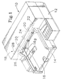
- Fig. 1 is an isometric view of a single-sheet printer, such printer employing the sheet handling system of the present invention as shown generally in dashed lines.
- Fig. 2 is an enlarged environmental view showing the printer in the vicinity of the invented system with the printer's pivot positioned in its initial position.
- Fig. 3 shows the invented system with a clutch having been actuated so as to engage a motor-driven gear.
- Fig. 4 shows the invented system with the printer's pivot in a first task-performing position.
- Fig. 5 shows the invented system at a moment during return of the pivot to its initial position.
- the invented system is suitable for use in virtually any printer wherein it is desired to perform a variety of different printing tasks.
- the system has proven particularly useful in single-sheet printers, such printers generally requiring that picking, kicking, and printing operations be performed. These tasks, it will be appreciated, lend themselves to execution by the type of system which will now be described.
- a single-sheet printer is thus depicted in Fig. 1 at 10, such printer providing the context in which the invented system is herein described.
- Printer 10 includes a chassis 12, a paper input tray 14, and a paper output tray 16.
- the printer which may also include other standard elements well known in the art, is capable of performing a series of different tasks on a sheet of paper, such tasks constituting what is known as a print cycle.
- a print cycle for example, paper is picked up from the input tray, printed on, and then kicked out (i.e. expelled) to the output tray.
- These operations are effected using a sheet handling system, one such system being shown generally by dashed lines at 18.
- system 18 includes a plurality of spaced rollers 20, each of which is operatively connected to a motor-driven drive shaft 22.
- the system also includes a pivot 24, the pivot selectively being rotatably movable to various positions wherein various printer tasks are performed.
- pivot rotation is controllably effected using a clutch 26 and a clutch-actuator/follower 28.
- Sheet handling system 18 is shown more specifically in Figs. 2-5, such drawings illustrating execution of a particular task (namely sheet kicking).
- task operation is effected by rotating pivot 24 from its initial position (shown in Fig. 2) to a first task-performing position (shown in Fig. 4), at which point the task is performed. The pivot is then rotated back to its initial position so that a new task operation may begin.
- first task-performing position corresponds to the pivot position wherein sheet kicking occurs and the initial position corresponds to the pivot position wherein sheet printing occurs.
- the depicted system also provides for pivot rotation to a second task-performing position wherein sheet picking occurs.
- the motor-driven gear which acts as the system's drive mechanism, and the clutch which is secured to the pivot, include a plurality of selectively interlocking teeth, providing for selected rotation of the pivot along with rotation of the gear. In this manner, the pivot is rotated from the initial position to the task-performing position, at which point the clutch is directed to disengage the gear so that the pivot may be returned to its initial position.
- Such pivot includes a cam-like sheet-directing member 24 a and a pair of elongate tracks 24 b , 24 c .
- the sheet-directing member extends substantially across the printer's chassis adjacent its input and output ports.
- Member 24 a is rotatable about shaft 22, such rotation being effective in directing passage of paper sheets into or out of the printer by camming action with the appropriate input or output tray.
- cam member rotation from the initial position to the first task-performing position results in a camming action with a wing 16 a (shown more completely in Fig.
- tracks 24 b and 24 c are fixed relative to the sheet-supporting member, each track being used during execution of a particular task as will be described below.
- track 24 b is used during sheet kicking and track 24 c is used during sheet picking.
- the tracks are defined by a series of upstanding ridges, each such ridge including a pair of generally upright side walls. The ridges extend generally angularly across the pivot so as to define a pair of sideways-adjacent grooves.
- the tracks are used during biased rotation of the pivot to control passage of the same to its initial position.
- the tracks are each of a predetermined length, the length of each track corresponding substantially to the distance traveled by the periphery of the pivot adjacent that track as the pivot moves from a task-performing position to the initial position.
- a bias element 32 such as a spring.
- the spring is secured to the clutch, which in turn is rotatable to a degree defined by a suitably positioned static stop (not shown).
- the stop restricts spring-biased rotation of the clutch/pivot combination, operatively preventing rotation thereof beyond the normally biased initial position shown in Fig. 2.
- spring-bias selectively is overcome by engagement of the clutch with gear 30 and may be opposed by other printer mechanism as will now be described.
- a clutch-actuator/follower 28 is operable selectively either as a clutch actuator wherein it urges clutch 26 into engagement with gear 30 (Fig. 3), or as a follower wherein it travels along one of the pivot's tracks to effect controlled pivot return (Fig. 5).
- component 28 hereinafter referred to simply as a follower, is provided with a first finger 28 a , a second finger 28 b , and a central projection 28 c .
- Follower 28 is preferably slidably mounted to the printer's chassis 12 so as to allow for arrangement of the follower in alternative configurations.
- finger 28 a contacts clutch protrusion 26 a , urging the clutch in to engagement with gear 30.
- the follower is tilted. Such tilt is due, at least partially, to camming contact of the same against a clutch ridge 26 b which is positioned on clutch protrusion 26 a .
- the follower may also be positioned in a second configuration wherein finger 28 a is urged into engagement with a side of one of the ridges which define the pivot's tracks. In either case, the follower acts to control movement of the pivot by applying a force to a component which moves relative thereto.
- a force substantially paralleling the shaft 22 may be supplied operatively by a printhead carriage 34, such carriage being mounted to reciprocate on a carriage shaft 36.
- the carriage includes one or more printheads whereby images are printed on a sheet of paper.
- the carriage is preferably motor-driven and processor or microprocessor controlled, allowing for corresponding control of pivot rotation as will now be described.
- the carriage Under processor control, the carriage is directed selectively into contact with the follower's second finger 28 b , effecting passage of the follower into contact with clutch 26.
- the clutch flexes under the force applied by the follower, bringing the clutch teeth into engagement with the corresponding teeth on gear 30. Because there is considerable play in the relationship between the follower and the chassis, and because of the first finger's relationship with clutch ridge 26 b , the follower tends to tilt counterclockwise as shown in Figs. 4 and 5.
- Central projection 28 c is thus placed into mating contact with a corresponding recess 34 a in carriage 34 and the carriage and follower are momentarily locked together.
- the follower as shown in Fig. 4, is then carried back toward its initial position under the direction of the processor controlled carriage.
- the first finger 28 a is eventually aligned with one of the tracks (track 24 b in the depicted sequence) and passed controlledly therethrough (shown in Fig. 5).
- movement of the follower in the manner just described results in a corresponding disengagement of the clutch from the motor-driven gear.
- the pivot will thus, in the absence of other forces which will be described below, pass readily to its initial position due to the applied spring bias.
- the rate at which the pivot returns to its initial position may also be controlled.
- rate it will be noted is related to the angulation of the track and the rate at which the follower is allowed to move along the track.
- the rate of return it will be understood, may also be affected by the properties of the materials used to form both the tracks and the follower, such properties being at least partially determinative of frictional forces involved.
Landscapes
- Handling Of Cut Paper (AREA)
- Handling Of Sheets (AREA)
- Delivering By Means Of Belts And Rollers (AREA)
Description
- The present invention relates generally to a system for use in selectively directing performance of various tasks by a printer, such as picking up, kicking out, and printing on paper sheets. More particularly, the invention relates to a paper handling system which employs a mechanism which is controllably movable between plural positions so as to controllably trigger execution of desired printer tasks.
- In order to operate effectively, printers must be able to perform various tasks during a print cycle, including picking up a sheet of paper, feeding it through the printer, and then kicking it out through the printer's output port. Such tasks are generally accomplished using a plurality of motor-driven gear trains, each such train being configured to execute a different one of the defined tasks. A problem with this arrangement, however, is that it requires the use of numerous, complex and costly gear mechanisms, driving the price of most single-sheet printers beyond the budgetary limits of many potential printer purchasers.
- One cost-saving approach to this problem has involved the use of a clutch which is selectively engagable with a single, motor-driven gear to bring about execution of each of the various tasks. An example of such an arrangement is set forth in U.S. Patent No. 5,000,594, which names Beehler et al. as inventors. In that patent, the inventors describe a clutch which is attached to a cam-like pivot, the pivot being used to direct a sheet of paper through a conventional print cycle. Upon engagement with the gear, the clutch drives the pivot from a spring-biased initial position to a task-performing position wherein the pivot directs execution of a particular task. Once the directed task is completed, the clutch is disengaged, allowing the pivot to return under spring bias to its initial position so that another task may be performed.
- Although the just-described arrangement has simplified the mechanism required to perform conventional printer tasks, it has left room for further improvements. For example, one area of difficulty concerns the rate at which the pivot returns to its initial position once a task has been performed. Known printers have provided for unrestrained spring-biased return of the pivot to the first position, such return being halted only by collision of the pivot or clutch with a static stop. Such collision, in turn, has led to excessive stresses on the components involved and to an undesirable clanking sound. Additionally, pivot return in known printers cannot be stopped until the pivot reaches its initial position, potentially leading to missed opportunities of saved time or energy between the performance of consecutive tasks.
- The present invention provides a printer having a sheet handling system, as specified in the claims hereinafter.
- The sheet handling system addresses the above-identified problems by using mechanism designed to allow for controlled passage of a pivot between an initial position and a task-performing position. Toward this end, the system's pivot includes a sheet-directing member and a track which is fixed relative thereto. The system also includes a follower which selectively is configured to travel controllably along the track. The pivot, which is normally biased toward the initial position, selectively is moved toward the task-performing position using a drive mechanism capable of overcoming the bias force. Movement in the opposite direction is controlled using the follower, such follower selectively being directed to apply a force against the track in opposition to the bias force. In the preferred embodiment, the applied force is controllably variable allowing for regulation of the rate at which the pivot returns to its initial position.
- Fig. 1 is an isometric view of a single-sheet printer, such printer employing the sheet handling system of the present invention as shown generally in dashed lines.
- Fig. 2 is an enlarged environmental view showing the printer in the vicinity of the invented system with the printer's pivot positioned in its initial position.
- Fig. 3 shows the invented system with a clutch having been actuated so as to engage a motor-driven gear.
- Fig. 4 shows the invented system with the printer's pivot in a first task-performing position.
- Fig. 5 shows the invented system at a moment during return of the pivot to its initial position.
- As stated above, the invented system is suitable for use in virtually any printer wherein it is desired to perform a variety of different printing tasks. The system, however, has proven particularly useful in single-sheet printers, such printers generally requiring that picking, kicking, and printing operations be performed. These tasks, it will be appreciated, lend themselves to execution by the type of system which will now be described. A single-sheet printer is thus depicted in Fig. 1 at 10, such printer providing the context in which the invented system is herein described.
-
Printer 10, it will be noted, includes achassis 12, apaper input tray 14, and apaper output tray 16. The printer, which may also include other standard elements well known in the art, is capable of performing a series of different tasks on a sheet of paper, such tasks constituting what is known as a print cycle. During a conventional print cycle, for example, paper is picked up from the input tray, printed on, and then kicked out (i.e. expelled) to the output tray. These operations are effected using a sheet handling system, one such system being shown generally by dashed lines at 18. As indicated,system 18 includes a plurality of spacedrollers 20, each of which is operatively connected to a motor-drivendrive shaft 22. The system also includes apivot 24, the pivot selectively being rotatably movable to various positions wherein various printer tasks are performed. As will be explained below, pivot rotation is controllably effected using aclutch 26 and a clutch-actuator/follower 28. -
Sheet handling system 18 is shown more specifically in Figs. 2-5, such drawings illustrating execution of a particular task (namely sheet kicking). As indicated, task operation is effected by rotatingpivot 24 from its initial position (shown in Fig. 2) to a first task-performing position (shown in Fig. 4), at which point the task is performed. The pivot is then rotated back to its initial position so that a new task operation may begin. In the depicted embodiment, such first task-performing position corresponds to the pivot position wherein sheet kicking occurs and the initial position corresponds to the pivot position wherein sheet printing occurs. It should be appreciated, however, that the depicted system also provides for pivot rotation to a second task-performing position wherein sheet picking occurs. - Focusing initially on rotation of the pivot from its initial position to its first task-performing position, and referring for this purpose specifically to Figs. 2-4, it will be appreciated that such rotation is effected by controlled flex of
clutch 26. As shown, the clutch is fixedly secured to the pivot and is rotatably mounted toshaft 22 so as to provide for rotation of the clutch and pivot in concert. Such rotation, as described in U.S. Patent No. 5,000,594, is effected by exerting a force against aclutch protrusion 26a so as to direct the clutch into resilient mating engagement with a motor-drivengear 30. The motor-driven gear, which acts as the system's drive mechanism, and the clutch which is secured to the pivot, include a plurality of selectively interlocking teeth, providing for selected rotation of the pivot along with rotation of the gear. In this manner, the pivot is rotated from the initial position to the task-performing position, at which point the clutch is directed to disengage the gear so that the pivot may be returned to its initial position. - Turning now to a specific description of the printer's
pivot 24, the component which directs a sheet of paper through the various printer tasks, it will be noted that such pivot includes a cam-like sheet-directingmember 24a and a pair ofelongate tracks Member 24a is rotatable aboutshaft 22, such rotation being effective in directing passage of paper sheets into or out of the printer by camming action with the appropriate input or output tray. As shown in Figs. 2-5, for example, cam member rotation from the initial position to the first task-performing position results in a camming action with awing 16a (shown more completely in Fig. 1), such wing being used to effect stacking of sheets on the printer's output tray as described in corresponding U.S. and European patent applications entitled "Paper Stacking System for Printers" which name Pearo et al. as inventors (US-A-5 324 020, EP-A-0 590 825, claiming the same priority date as the present application). As indicated,pivot 24 effects rotation of the wings as it moves toward its first task-performing position. - As indicated generally in Figs. 2-5, but as best shown in Fig. 4,
tracks track 24b is used during sheet kicking andtrack 24c is used during sheet picking. The tracks, it will be noted, are defined by a series of upstanding ridges, each such ridge including a pair of generally upright side walls. The ridges extend generally angularly across the pivot so as to define a pair of sideways-adjacent grooves. As will be appreciated upon reading further, the tracks are used during biased rotation of the pivot to control passage of the same to its initial position. The tracks are each of a predetermined length, the length of each track corresponding substantially to the distance traveled by the periphery of the pivot adjacent that track as the pivot moves from a task-performing position to the initial position. - Upon further review of Figs. 2-5, the reader will note that the pivot is yieldably biased toward its initial position via a
bias element 32 such as a spring. The spring is secured to the clutch, which in turn is rotatable to a degree defined by a suitably positioned static stop (not shown). The stop restricts spring-biased rotation of the clutch/pivot combination, operatively preventing rotation thereof beyond the normally biased initial position shown in Fig. 2. As suggested by the pivot progression described above, spring-bias selectively is overcome by engagement of the clutch withgear 30 and may be opposed by other printer mechanism as will now be described. - In Figs. 3-5, pivot rotation is shown, control of such pivot rotation being effected using a clutch-actuator/
follower 28. Such component, it will be appreciated, is operable selectively either as a clutch actuator wherein it urges clutch 26 into engagement with gear 30 (Fig. 3), or as a follower wherein it travels along one of the pivot's tracks to effect controlled pivot return (Fig. 5). To accomplish such control,component 28, hereinafter referred to simply as a follower, is provided with afirst finger 28a, asecond finger 28b, and acentral projection 28c. -
Follower 28 is preferably slidably mounted to the printer'schassis 12 so as to allow for arrangement of the follower in alternative configurations. In a first configuration, shown in Fig. 3,finger 28a contactsclutch protrusion 26a, urging the clutch in to engagement withgear 30. As the clutch turns with the pivot under the direction ofgear 30, the follower is tilted. Such tilt is due, at least partially, to camming contact of the same against aclutch ridge 26b which is positioned onclutch protrusion 26a. As shown in Fig. 5, the follower may also be positioned in a second configuration whereinfinger 28a is urged into engagement with a side of one of the ridges which define the pivot's tracks. In either case, the follower acts to control movement of the pivot by applying a force to a component which moves relative thereto. - As shown in Fig. 3, a force substantially paralleling the
shaft 22 may be supplied operatively by aprinthead carriage 34, such carriage being mounted to reciprocate on acarriage shaft 36. The carriage, it will be appreciated, includes one or more printheads whereby images are printed on a sheet of paper. As is conventional in most printer applications, the carriage is preferably motor-driven and processor or microprocessor controlled, allowing for corresponding control of pivot rotation as will now be described. - Under processor control, the carriage is directed selectively into contact with the follower's
second finger 28b, effecting passage of the follower into contact withclutch 26. The clutch flexes under the force applied by the follower, bringing the clutch teeth into engagement with the corresponding teeth ongear 30. Because there is considerable play in the relationship between the follower and the chassis, and because of the first finger's relationship withclutch ridge 26b, the follower tends to tilt counterclockwise as shown in Figs. 4 and 5.Central projection 28c is thus placed into mating contact with acorresponding recess 34a incarriage 34 and the carriage and follower are momentarily locked together. - The follower, as shown in Fig. 4, is then carried back toward its initial position under the direction of the processor controlled carriage. The
first finger 28a is eventually aligned with one of the tracks (track 24b in the depicted sequence) and passed controlledly therethrough (shown in Fig. 5). As will be appreciated upon reference to the drawings, movement of the follower in the manner just described results in a corresponding disengagement of the clutch from the motor-driven gear. The pivot will thus, in the absence of other forces which will be described below, pass readily to its initial position due to the applied spring bias. - Turning now to Fig. 5, and considering in detail the return of the pivot to its initial position, it will be appreciated that such return is opposed by forces resulting from the follower's engagement with
track 24b. As indicated, rotation of the pivot results in the follower'sfinger 28a contacting one of the ridges which definetrack 24b. The ridge will thus act as an impediment to pivot rotation, any given position along the ridge's length being suitable to act as a stop. The present arrangement therefore allows for stopping of the pivot's rotation at any point during pivot return. Pivot rotation is possible only as the follower is allowed by the carriage to slide down the track. - In view of the just-described arrangement, it should be appreciated that the rate at which the pivot returns to its initial position may also be controlled. Such rate, it will be noted is related to the angulation of the track and the rate at which the follower is allowed to move along the track. Because the carriage is processor controlled, and because it is the carriage which determines how far the follower may move, it is possible straightforwardly to control the rate of pivot movement via suitable programming of the processor. The rate of return, it will be understood, may also be affected by the properties of the materials used to form both the tracks and the follower, such properties being at least partially determinative of frictional forces involved.
- Conventional printers typically employ mechanism such as a printhead carriage which is driven back and forth during the printer's print cycle. Such mechanism, it will be understood, may be used to controlledly actuate movement of the pivot so as to trigger different tasks as described above. The invented system is therefore applicable to virtually any printer which employs a mechanism such as a printhead carriage and is intended to perform tasks such as the picking, printing, and kicking of paper. While the best mode and preferred embodiment of the invention have been set forth herein, it should be appreciated that variations and modifications may be made without departing from the scope of the invention as defined by the claims.
Claims (9)
- A printer (10) having a sheet handling system (18) which directs movement of a sheet through the printer, said system comprising:a pivot (24) having a sheet-directing member (24a) and a track (24b,24c) fixed thereto, said pivot, member and track being movable between an initial position, and a task-performing position where the sheet-directing member directs movement of a sheet through the printer;biassing means (32) providing a force biassing the pivot towards the initial position,a drive mechanism (30) for driving the pivot, member and track from the initial position to the task-performing position against the biassing force,a follower (28) arranged to engage said track when said member reaches the task-performing position to apply a force through said track frictionally opposing the biassing movement of the pivot back towards the initial position.
- A printer according to claim 1, which further comprises a clutch (26) mounted to said pivot for selective-engagement with the drive mechanism.
- A printer according to claim 2, wherein said follower is arranged for engagement with said clutch at the initial position to drive the clutch into engagement with the drive mechanism.
- A printer according to any of claims 1 to 3, which further comprises a motor-driven printhead carriage (34), which carriage engages said follower to urge the follower into engagement with the track.
- A printer according to any of claims 1 to 4, wherein the initial position is a printing position and wherein the printer includes means for printing on the sheet at the printing position.
- A printer according to any of claims 1 to 5, wherein the task-performing position is a sheet kicking position at which the sheet-directing member kicks a printed sheet out of the printer.
- A printer according to claim 6, which comprises a second track which is engaged by said follower when said member reaches a second task-performing position, said second task-performing position being a sheet picking position at which the sheet directing member picks a sheet into the printer for printing.
- A printer according to any of claims 1 to 7, wherein the, or each, track is in the form of a groove which slidingly captures the follower.
- A printer according to any of claims 1 to 8, which includes means to vary the force applied by the follower to oppose the biassing movement of the pivot back towards the initial position.
Applications Claiming Priority (2)
| Application Number | Priority Date | Filing Date | Title |
|---|---|---|---|
| US07/954,619 US5269613A (en) | 1992-09-29 | 1992-09-29 | Paper handling system for printers |
| US954619 | 1992-09-29 |
Publications (2)
| Publication Number | Publication Date |
|---|---|
| EP0590823A1 EP0590823A1 (en) | 1994-04-06 |
| EP0590823B1 true EP0590823B1 (en) | 1997-11-12 |
Family
ID=25495697
Family Applications (1)
| Application Number | Title | Priority Date | Filing Date |
|---|---|---|---|
| EP93307217A Expired - Lifetime EP0590823B1 (en) | 1992-09-29 | 1993-09-14 | Paper handling system for printers |
Country Status (4)
| Country | Link |
|---|---|
| US (1) | US5269613A (en) |
| EP (1) | EP0590823B1 (en) |
| JP (1) | JP3481273B2 (en) |
| DE (1) | DE69315166T2 (en) |
Families Citing this family (11)
| Publication number | Priority date | Publication date | Assignee | Title |
|---|---|---|---|---|
| DE69226884T2 (en) * | 1991-12-20 | 1999-05-12 | Seiko Epson Corp., Tokio/Tokyo | Printing device |
| US5433543A (en) * | 1993-10-29 | 1995-07-18 | Hewlett-Packard Company | Media feed and carriage motion mechanism for shuttle-type printers |
| USD364891S (en) | 1994-06-10 | 1995-12-05 | Hewlett-Packard Company | Combined wing and spring shield for a printer media handling system |
| US5603493A (en) * | 1994-12-03 | 1997-02-18 | Hewlett Packard Company | System for use in handling media |
| US5536000A (en) * | 1995-01-30 | 1996-07-16 | Hewlett-Packard Company | Adjustable sheet media handling system with active sheet media drop |
| CA2200247C (en) * | 1996-10-29 | 2004-03-16 | Thomas E. Mccue, Jr. | Z-fold print media handling system |
| KR100205752B1 (en) * | 1997-01-06 | 1999-07-01 | 윤종용 | Inkjet printer which prevents jam by paper warping phenomenon |
| US6350073B1 (en) | 1999-05-25 | 2002-02-26 | Hewlett-Packard Company | Z-fold print media handling system |
| US6092948A (en) * | 1999-06-30 | 2000-07-25 | Xerox Corporation | Method and mechanism for supporting and stacking liquid ink printed sheets |
| US6652174B1 (en) * | 1999-07-27 | 2003-11-25 | Hewlett-Packard Development Company, L.P. | Hybrid set-top box and printing device |
| US20040141792A1 (en) * | 2003-01-16 | 2004-07-22 | Brinkly Richard Lee | Output media handling |
Family Cites Families (7)
| Publication number | Priority date | Publication date | Assignee | Title |
|---|---|---|---|---|
| GB2046177B (en) * | 1979-03-26 | 1983-04-20 | Seiko Instr & Electronics | Printer |
| US4480825A (en) * | 1980-02-11 | 1984-11-06 | Savin Corporation | Sheet set separator for electrophotographic copier |
| DE3309985A1 (en) * | 1982-06-18 | 1984-02-16 | Ricoh Co., Ltd., Tokyo | Sheet-feeding device |
| JPH0355552Y2 (en) * | 1984-11-08 | 1991-12-11 | ||
| US5000594A (en) * | 1989-10-13 | 1991-03-19 | Hewlett-Packard Company | Printer with carriage-actuated clutch and paper-feed mechanism |
| US5188353A (en) * | 1990-08-17 | 1993-02-23 | Xerox Corporation | Disk stacker including tamping mechanism capable of cross-direction offsetting |
| US5226743A (en) * | 1991-04-16 | 1993-07-13 | Hewlett-Packard Company | Method and apparatus for paper control in a printer |
-
1992
- 1992-09-29 US US07/954,619 patent/US5269613A/en not_active Expired - Lifetime
-
1993
- 1993-09-14 DE DE69315166T patent/DE69315166T2/en not_active Expired - Fee Related
- 1993-09-14 EP EP93307217A patent/EP0590823B1/en not_active Expired - Lifetime
- 1993-09-27 JP JP23976593A patent/JP3481273B2/en not_active Expired - Fee Related
Also Published As
| Publication number | Publication date |
|---|---|
| DE69315166T2 (en) | 1998-03-12 |
| JP3481273B2 (en) | 2003-12-22 |
| JPH06219000A (en) | 1994-08-09 |
| US5269613A (en) | 1993-12-14 |
| DE69315166D1 (en) | 1997-12-18 |
| EP0590823A1 (en) | 1994-04-06 |
Similar Documents
| Publication | Publication Date | Title |
|---|---|---|
| US5269613A (en) | Paper handling system for printers | |
| EP0509667B1 (en) | Method and apparatus for paper control and skew correction in a printer | |
| US5238235A (en) | Sheet feeding apparatus | |
| JPS60264268A (en) | Printer with cutting mechanism | |
| US5624196A (en) | Method and apparatus for paper control including kickers | |
| EP0422794B1 (en) | Printer with carriage-actuated clutch and paper-feed mechanism | |
| US5427462A (en) | Method and apparatus for paper control and skew correction in a printer | |
| US5873664A (en) | Printer apparatus | |
| US6311971B1 (en) | Stacker controlling curl | |
| US5803337A (en) | Electric stapler | |
| JPH0613378B2 (en) | Copy sheet rotating device | |
| JP2519886B2 (en) | Small printer | |
| JPH02219601A (en) | Stapler | |
| US4581665A (en) | Mode changing mechanism for a tape player | |
| US4941762A (en) | Switching mechanism for a paper holding roller of a printer | |
| EP0310002B1 (en) | Head driving mechanism for recording apparatus | |
| JP3478599B2 (en) | Sheet feeder mechanism | |
| SE450305B (en) | MECHANISM FOR QUICK RINSE UP AND BACK IN A RECORDER | |
| US5106213A (en) | Thermal print head control mechanism | |
| JPH07114047B2 (en) | Cassette type tape recorder | |
| US5120146A (en) | Printer having a bail roller opening and closing mechanism | |
| JPS61157831A (en) | Clutch | |
| JPH0647862Y2 (en) | Printer paper feed mechanism | |
| JP2570854B2 (en) | Recording device | |
| JPH0248974Y2 (en) |
Legal Events
| Date | Code | Title | Description |
|---|---|---|---|
| PUAI | Public reference made under article 153(3) epc to a published international application that has entered the european phase |
Free format text: ORIGINAL CODE: 0009012 |
|
| AK | Designated contracting states |
Kind code of ref document: A1 Designated state(s): DE FR GB IT |
|
| 17P | Request for examination filed |
Effective date: 19940909 |
|
| 17Q | First examination report despatched |
Effective date: 19951212 |
|
| GRAG | Despatch of communication of intention to grant |
Free format text: ORIGINAL CODE: EPIDOS AGRA |
|
| GRAH | Despatch of communication of intention to grant a patent |
Free format text: ORIGINAL CODE: EPIDOS IGRA |
|
| GRAH | Despatch of communication of intention to grant a patent |
Free format text: ORIGINAL CODE: EPIDOS IGRA |
|
| GRAA | (expected) grant |
Free format text: ORIGINAL CODE: 0009210 |
|
| ITF | It: translation for a ep patent filed | ||
| AK | Designated contracting states |
Kind code of ref document: B1 Designated state(s): DE FR GB IT |
|
| REF | Corresponds to: |
Ref document number: 69315166 Country of ref document: DE Date of ref document: 19971218 |
|
| ET | Fr: translation filed | ||
| PLBE | No opposition filed within time limit |
Free format text: ORIGINAL CODE: 0009261 |
|
| STAA | Information on the status of an ep patent application or granted ep patent |
Free format text: STATUS: NO OPPOSITION FILED WITHIN TIME LIMIT |
|
| 26N | No opposition filed | ||
| REG | Reference to a national code |
Ref country code: GB Ref legal event code: 732E |
|
| REG | Reference to a national code |
Ref country code: FR Ref legal event code: TP |
|
| REG | Reference to a national code |
Ref country code: GB Ref legal event code: IF02 |
|
| PGFP | Annual fee paid to national office [announced via postgrant information from national office to epo] |
Ref country code: FR Payment date: 20060918 Year of fee payment: 14 |
|
| PGFP | Annual fee paid to national office [announced via postgrant information from national office to epo] |
Ref country code: DE Payment date: 20061031 Year of fee payment: 14 |
|
| PGFP | Annual fee paid to national office [announced via postgrant information from national office to epo] |
Ref country code: IT Payment date: 20070927 Year of fee payment: 15 |
|
| PG25 | Lapsed in a contracting state [announced via postgrant information from national office to epo] |
Ref country code: DE Free format text: LAPSE BECAUSE OF NON-PAYMENT OF DUE FEES Effective date: 20080401 |
|
| REG | Reference to a national code |
Ref country code: FR Ref legal event code: ST Effective date: 20080531 |
|
| PG25 | Lapsed in a contracting state [announced via postgrant information from national office to epo] |
Ref country code: FR Free format text: LAPSE BECAUSE OF NON-PAYMENT OF DUE FEES Effective date: 20071001 |
|
| PG25 | Lapsed in a contracting state [announced via postgrant information from national office to epo] |
Ref country code: IT Free format text: LAPSE BECAUSE OF NON-PAYMENT OF DUE FEES Effective date: 20080914 |
|
| PGFP | Annual fee paid to national office [announced via postgrant information from national office to epo] |
Ref country code: GB Payment date: 20110926 Year of fee payment: 19 |
|
| REG | Reference to a national code |
Ref country code: GB Ref legal event code: 732E Free format text: REGISTERED BETWEEN 20120329 AND 20120404 |
|
| GBPC | Gb: european patent ceased through non-payment of renewal fee |
Effective date: 20120914 |
|
| PG25 | Lapsed in a contracting state [announced via postgrant information from national office to epo] |
Ref country code: GB Free format text: LAPSE BECAUSE OF NON-PAYMENT OF DUE FEES Effective date: 20120914 |