EP0590832A2 - Stereoskopisches Darstellungsgerät - Google Patents
Stereoskopisches Darstellungsgerät Download PDFInfo
- Publication number
- EP0590832A2 EP0590832A2 EP93307334A EP93307334A EP0590832A2 EP 0590832 A2 EP0590832 A2 EP 0590832A2 EP 93307334 A EP93307334 A EP 93307334A EP 93307334 A EP93307334 A EP 93307334A EP 0590832 A2 EP0590832 A2 EP 0590832A2
- Authority
- EP
- European Patent Office
- Prior art keywords
- image
- light
- display
- pixel
- phase distribution
- Prior art date
- Legal status (The legal status is an assumption and is not a legal conclusion. Google has not performed a legal analysis and makes no representation as to the accuracy of the status listed.)
- Granted
Links
Images


Classifications
-
- G—PHYSICS
- G03—PHOTOGRAPHY; CINEMATOGRAPHY; ANALOGOUS TECHNIQUES USING WAVES OTHER THAN OPTICAL WAVES; ELECTROGRAPHY; HOLOGRAPHY
- G03H—HOLOGRAPHIC PROCESSES OR APPARATUS
- G03H1/00—Holographic processes or apparatus using light, infrared or ultraviolet waves for obtaining holograms or for obtaining an image from them; Details peculiar thereto
- G03H1/04—Processes or apparatus for producing holograms
- G03H1/0402—Recording geometries or arrangements
- G03H1/0406—Image plane or focused image holograms, i.e. an image of the object or holobject is formed on, in or across the recording plane
-
- G—PHYSICS
- G02—OPTICS
- G02B—OPTICAL ELEMENTS, SYSTEMS OR APPARATUS
- G02B30/00—Optical systems or apparatus for producing three-dimensional [3D] effects, e.g. stereoscopic images
- G02B30/20—Optical systems or apparatus for producing three-dimensional [3D] effects, e.g. stereoscopic images by providing first and second parallax images to an observer's left and right eyes
- G02B30/26—Optical systems or apparatus for producing three-dimensional [3D] effects, e.g. stereoscopic images by providing first and second parallax images to an observer's left and right eyes of the autostereoscopic type
- G02B30/27—Optical systems or apparatus for producing three-dimensional [3D] effects, e.g. stereoscopic images by providing first and second parallax images to an observer's left and right eyes of the autostereoscopic type involving lenticular arrays
-
- G—PHYSICS
- G03—PHOTOGRAPHY; CINEMATOGRAPHY; ANALOGOUS TECHNIQUES USING WAVES OTHER THAN OPTICAL WAVES; ELECTROGRAPHY; HOLOGRAPHY
- G03H—HOLOGRAPHIC PROCESSES OR APPARATUS
- G03H1/00—Holographic processes or apparatus using light, infrared or ultraviolet waves for obtaining holograms or for obtaining an image from them; Details peculiar thereto
- G03H1/04—Processes or apparatus for producing holograms
- G03H1/08—Synthesising holograms, i.e. holograms synthesized from objects or objects from holograms
-
- G—PHYSICS
- G03—PHOTOGRAPHY; CINEMATOGRAPHY; ANALOGOUS TECHNIQUES USING WAVES OTHER THAN OPTICAL WAVES; ELECTROGRAPHY; HOLOGRAPHY
- G03H—HOLOGRAPHIC PROCESSES OR APPARATUS
- G03H1/00—Holographic processes or apparatus using light, infrared or ultraviolet waves for obtaining holograms or for obtaining an image from them; Details peculiar thereto
- G03H1/26—Processes or apparatus specially adapted to produce multiple sub- holograms or to obtain images from them, e.g. multicolour technique
- G03H1/268—Holographic stereogram
Definitions
- the invention relates to a stereoscopic display apparatus for displaying a solid image from a plurality of 2-dimensional images at different visual point positions and, more particularly, to a stereoscopic display apparatus for performing a stereoscopic display which has been known as an image type holographic stereogram.
- the conventional stereoscopic display method relates to the double-eye type represented by a glasses type and is a system in which different images are seen to the right and left eyes and a stereoscopic feeling is obtained by a vergence of both eyes or a parallax of both eyes.
- a holographic stereogram can be mentioned as means for eliminating such problems.
- a 2-dimensional video image including a parallax is recorded on slit-like segment holograms which are elongated in the vertical direction and a number of such segment holograms are arranged in the horizontal direction. Therefore, even when the observer moves the head to the right and left, a natural stereoscopic feeling can be obtained.
- a holographic stereogram including a parallax in the vertical direction is also a holographic stereogram including a parallax in the vertical direction.
- a laser beam 342 is subsequently irradiated to a film 336 obtained by the photographing in Fig. 1.
- a transmission light which passed through the film 336 is projected onto a diffusing plate 340 through a lens 338, thereby generating an object light 344.
- a slit 350 of a slit plate 348 is located in front of a hologram dry plate 352 in correspondence to the photographing position.
- An interference fringe (phase distribution) is obtained by an interference between a reference light 354 and the object light 344 and is exposed and recorded onto the hologram dry plate 352.
- a laser beam (reproduction light) is irradiated onto the hologram dry plate 352 formed in Fig. 2 so as to be converged by a reproduction light source 355 which is shown as a virtual image.
- Another hologram dry plate is provided at the display position of the image due to the object light 344 which was wave front converted by the exposed hologram dry plate 352.
- the hologram dry plate is exposed by irradiating the reference light 362 thereto, thereby forming an imaged holographic stereogram (hereinafter, referred to as an "image type holographic stereogram") 360.
- an image type holographic stereogram hereinafter, referred to as an "image type holographic stereogram
- a reproduction light 364 is irradiated to the image type holographic stereogram 360, the reproduction light is converted into the wave front, so that a solid image to be seen from a visual field region 366.
- a solid image exists near the hologram surface in order to reduce a fatigue of the eyes of the observer.
- the holographic stereogram of Fig. 1 it is necessary to convert the image photographed by the camera in order to reconstruct so as to overlap a solid image onto the hologram surface.
- an image type holographic stereogram of Fig. 4 since a 2-dimensional image exists on the hologram surface, the solid image can be overlapped onto the hologram surface without converting the image.
- There is also an advantage such that even when a wavelength of reference light which is irradiated to the hologram changes, the image plane exists on the hologram surface and no color aberration occurs and the like. Therefore, it can be said that a solid image can be more easily seen in case of the stereoscopic display by the image type holographic stereogram.
- Such a hologram can be electronically displayed by using, for example, a space light modulating device using a liquid crystal.
- a space light modulating device using a liquid crystal.
- the image type holographic stereogram it is necessary to calculate a phase distribution from a 2-dimensional image.
- the hologram surface is divided into micro hologram regions. Aphase distribution is calculated from the position coordinates and luminance of all of the sampling points of the object with regard to one microregion. Such a calculation is executed with respect to all of the micro hologram regions.
- a stereoscopic display apparatus comprising: an image display section to display a plurality of 2-dimensional images of different visual directions; and a beam deflecting section to deflect the light from pixels constructing the images displayed by the image display section.
- the beam deflecting section is arranged closely in front of the image display section. Aplurality of 2-dimensional images of different visual directions are sequentially displayed in the image display section.
- the light from each pixel is deflected by the beam deflecting section synchronously with the display of the 2-dimensional images in a manner such that the light from each pixel is directed toward an area in which a visual point has been set to obtain each image.
- a switching operation in this instance is executed at a high speed.
- a visible region or “visible range” in which a solid image can be seen
- the right and left eyes of the observer see the 2-dimensional images having a parallax when they are seen from different visual points at which the right and left eyes are located, so that the observer can see a solid image.
- a space light modulating device such as a liquid crystal device or the like is used as a beam deflecting section.
- a phase distribution to decide the deflecting direction is previously calculated for each of images of different visual directions and is fixedly prepared as a table data.
- the phase distribution of the table data corresponding to the image is read out and the space light modulating device is driven in which case there is no need to calculate the phase distribution each time the image is switched.
- a plurality of 2-dimensional images of different visual directions and the phase distribution information to deflect the pixels of each image into the region (virtual opening) set upon formation of the image are prepared, so that a solid image can be stereoscopically displayed by using a plurality of 2-dimensional images of different visual directions.
- embodiments of the invention may provide a stereoscopic display apparatus which can perform a stereoscopic display without needing to calculate the phase distribution even when a 2- dimensional image changes with respect to an image type holographic stereogram as a target. Further, embodiments may provide a stereoscopic display apparatus for displaying a solid image from a plurality of 2-dimensional images of different visual directions, namely, a stereoscopic display apparatus for displaying a solid image by an image holographic stereogram.
- Fig. 5 shows a simplified construction of an embodiment of the invention.
- the stereoscopic display apparatus comprises: a 2-dimensional image display section 10 as image display means; a phase distribution display section 12 as beam deflecting means; a display control section 14; a 2-dimensional image storing table 16; and a phase distribution storing table 18.
- a liquid crystal display is used as a 2-dimensional image display section 10.
- a space light modulating device using a liquid crystal device or the like can be used as a phase distribution display section 12.
- the display control section 14 is realized by a computer.
- the 2-dimensional image storing table 16 and the phase distribution storing table 18 can be realized by memory devices.
- a plurality of 2-dimensional images which are used for stereoscopic display and which were seen from different visual point positions, what are called 2-dimensional images of different visual directions have previously been stored in the 2-dimensional image storing table 16, while using areas in which visual points have been set as instruction parameters. It is also possible to produce a plurality of 2-dimensional images of different visual directions by a CAD system or the like in a real-time manner and to supply them to the display control section 14 without storing into the 2-dimensional image storing table 16.
- phase distribution storing table 18 Information of the phase distributions which had previously been calculated and are used to deflect the light from each pixel of the 2-dimensional image display section 12 toward a region (virtual opening) in which the visual point has been set has been stored in the phase distribution storing table 18 in order to produce the 2-dimensional image for each of the images of different visual directions.
- the display control section 14 sequentially reads out the 2-dimensional images of different directions from the 2-dimensional image storing table 16 and displays in the 2-dimensional image display section 10.
- the corresponding phase distribution is read out from the phase distribution storing table 18 synchronously with the display of the 2-dimensional image and displays in the phase distribution display section 12.
- the light from each pixel of the 2-dimensional image displayed in the 2-dimensional image display section 10 is subjected to the deflection due to the phase distribution displayed in the corresponding phase distribution display section 12.
- the light from each pixel is deflected toward the region (virtual opening) in which the visual point position of each 2-dimensional image has been set, thereby allowing a 2- dimensional image of different parallaxes to be seen to the right and left eyes of the observer and enabling a solid image to be recognized.
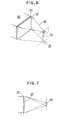
- Fig. 6 shows an example of the formation of an image type holographic stereogram.
- Fig. 7 shows a plan view of Fig. 6.
- the position at which a diffusing plate 24 is disposed corresponds to the position at which an object was photographed by the camera.
- a 2- dimensional image 22 is an image which is obtained when the object is seen at the position of the diffusing plate 24.
- a size of diffusing plate 24 is equal to a size of virtual opening that is determined by the visual point setting area in the holographic stereogram.
- Each pixel of the 2-dimensional image 22 to be recorded onto the hologram 20 receives an object light 28 derived from the region of the diffusing plate 24 by the irradiation of a laser beam 26.
- the object light 28 which passed through each pixel of the 2-dimensional image 22 enters onto the hologram 20 and is interfered with a reference light 30 from the opposite side, so that the direction of each pixel of the 2-dimensional image is recorded as a form of an interference fringe.
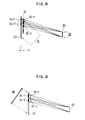
- the recording of the interference fringe will now be described in detail with reference to Fig. 8.
- Fig. 8 shows the two pixels 32-1 and 32-2 as an example.
- the light from the diffusing plate 24 is subjected to the modulation of the transmission factors which the pixels 32-1 and 32-2 have and enters the hologram 20.
- interference fringes 34-1 and 34-2 which are recorded on the hologram 20 are separated every pixels 32-1 and 32-2. Intensities of the interference fringes 34-1 and 34-2 depend on the transmission factors of the pixels 32-1 and 32-2. Distributions of the interference fringes 34-1 and 34-2 relate to the positions of the diffusing plate 24 and the pixels 32-1 and 32-2.
- the reference light 30 has been inputted from the rear side of the hologram 20.
- the reference light 30 is inputted from the same surface as the 2-dimensional image 20. But, in case of obtaining the interference fringe, namely, phase distribution of the hologram 20 by the calculation, the direction of the reference light is not physically restricted.
- Fig. 9 shows the reconstruction of a solid image by the hologram 20 formed by Fig. 8.
- the interference fringes 34-1 and 34-2 in which each pixel was recorded generates the lights of pixel openings 35-1 and 35-2.
- the lights are diffracted toward a visible range 40 in which the diffusing plate has been disposed.
- the intensities of the interference fringes 34-1 and 34-2 are proportional to the intensity of each pixel of the recorded 2-dimensional image, the whole image of the recorded 2-dimensional image can be seen at the position of the visible range 40 in which the diffusing plate 24 in Fig.
- Fig. 10 shows the reconstructing principle of the stereoscopic display apparatus.
- the phase distribution display section 12 is disposed closely in front of the 2-dimensional image display section 10 of the transmission factor modulating type.
- the distribution of the interference fringes in the phase distribution display section 12 is determined by the positional relation between the pixels 32-1 and 32-2 and the diffusing plate 24, by once calculating and storing the interference fringes (phase distributions) 34-1 and 34-2 which are displayed in the phase distribution display section 12 and are used to deflect the light to the visible range 40 corresponding to the set position of the diffusing plate, there is no need to again calculate them. That is, the phase distributions which are displayed in the phase distribution display section 12 can be fixedly supplied into a read only memory or supplied as table data.
- the transmission factor of the image can be realized by changing the intensities of lights to reconstruct the interference fringes 34-1 and 34-2 of the display section 12. Therefore, the 2-dimensional image display section 10 is provided at a position near the phase distribution display section 12. The light intensity of a reproduction light 36 is changed by the transmission factors of the pixels 32-1 and 32-2 of the display image and the lights are inputted to the interference fringes 34-1 and 34-2 of the phase distribution display section 12.
- Fig. 11 is a perspective view of a stereoscopic display apparatus shown in Fig. 10.
- the phase distribution display section 12 is arranged at a position near the 2-dimensional image display section 10 and the reproduction light 36 is irradiated from the rear side of the display section 10.
- the image type holographic stereogram it is necessary to reconstruct 2-dimensional images in the case where they were seen from a plurality of different opening positions in the visible region. That is, as shown in Fig. 11, it is necessary to diffract the light toward a plurality of openings which are set in a visible region 45 from the same pixel position of the 2- dimensional image display section 10.
- the diffracting direction of the light which is emitted from the same pixel of the display section 10 is changed with the elapse of time, thereby enabling a solid image to be seen by an after image.
- the light is diffracted toward a virtual opening area A at time t1 and the light is diffracted toward a different virtual opening area A ;+k at time t2.
- Fig. 12A is a side elevational view showing further in detail the light deflection by the phase distribution display section 12.
- Fig. 12B is a plan view of Fig. 12A.
- the visible region 45 is divided as a virtual opening in the horizontal direction, thereby obtaining stripe-shaped regions which are long in the vertical direction.
- a 2- dimensional image obtained by being observed from the central virtual opening area A is displayed in the 2- dimensional image display section 10.
- one interference fringe is deflected in the phase distribution display section 12 so as to be irradiated to the whole region in the height direction of the virtual opening A with respect to the vertical direction of Fig. 12A.
- each interference fringe of the phase distribution display section 12 is deflected so as to be collected toward the central virtual opening area A of the visible region 45.
- phase distribution (interference fringe) which gives a light deflection that is determined every image of a different visual direction has previously been stored as table data in the phase distribution storing table 18 shown in Fig. 5.
- the formation of the data which is stored into the phase distribution storing table 18 will now be described.
- One laser beam is divided into two beams.
- One of the two laser beams is irradiated to an object, so that a laser beam (object light) is scattered by the object.
- a hologram is obtained by an interference of two light fluxes of the laser beam (object light) and another laser beam (reference light).
- a wave front of the reference light is set to R ⁇ exp(j ⁇ r ) and a wave front of the object light is set to O ⁇ exp(j ⁇ o )
- an exposing intensity I H of the hologram is
- the first term of the right side of the equation (2) indicates that the wave front from the object was reproduced.
- the second term of the right side denotes a conjugate wave of the object light. From the above description of the principle, it will be understood that it is sufficient to calculate only the third term of the right side of the equation (1) in the calculation of the phase distribution of the hologram.
- Fig. 13 shows the principle of the calculation of the phase distribution in the holographic stereogram.
- the reference light is constructed by a plane wave
- the coordinate value in the Z-axis direction of the 2-dimensional image 22 is equal to Z ; and is constant.
- the exposing intensity I H at a point Q having the coordinates (X hi , Y hi ) on a holographic stereogram 44 is where, k denotes the number of waves of the laser beam
- Fig. 14 shows a deflecting function of the phase distribution display section 12 of the invention which is used to stereoscopically display a solid image having parallaxes in the horizontal and vertical directions.
- the phase distribution display section 12 total (M x N) one-pixel phase display sections 46 each corresponding to one pixel of the 2-dimensional image are arranged, in which (M) phase display sections 46 are arranged in the vertical direction and (N) phase display sections 46 are arranged in the horizontal direction.
- the horizontal direction is expressed by (j) and the vertical direction is expressed by (i)
- the pixel corresponding to an arbitrary one-pixel phase display section 46 is expressed by P lj .
- a virtual opening 48 is arranged at the position serving as a visible region for the phase display section 12.
- Total (n x m) virtual openings 48 are arranged, in which (n) virtual openings 48 are arranged in the horizontal direction and (m) virtual openings 48 are arranged in the vertical direction.
- an arbitrary virtual opening region is expressed by S kf .
- An attention is now paid to a phase display section 46 of one pixel at the right upper corner of the phase distribution display section 12.
- a deflecting state of the display light from the corresponding pixel Pin is shown in Fig. 14.
- the light from the corresponding pixel P 1N is deflected for regions S 11 to S nm of the virtual opening 48 as shown in the diagram.
- Fig. 15 shows a calculating method of a phase distribution to realize the deflecting function shown in Fig. 14.
- a calculating method of a phase distribution in the one-pixel phase display section 46 of the corresponding pixel P lj is shown with respect to the relation with a region S kC of one virtual opening 48 as an example.
- a plurality of virtual point light sources 50 are arranged in the virtual opening 48 in the horizontal and vertical directions.
- Avirtual reference light 52 is also set.
- a phase distribution is calculated by the equations (3) and (4) every pixel 54 for a phase display constructing the 1-pixel phase display section 46 with respect to all of the virtual point light sources 50.
- 2-dimensional image data as shown in Fig.
- a plurality of 2- dimensional image data G 11 to G mn in the case where the virtual opening areas S 11 to S mn were seen as visual points are prepared and time-divisionally displayed. Therefore, the virtual openings 48 shown in Fig. 14 change in the horizontal and vertical directions with the elapse of time in association with the switching of the 2-dimensional image data G 11 to G mn .
- the calculation of the phase distribution of Fig. 15 is executed with respect to each of the virtual opening regions whose positions change with the elapse of time in association with the 2-dimensional images G 11 to G mn .
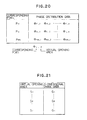
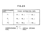
- phase distributions ⁇ ij,11 to ⁇ ij,mn are calculated so as to deflect the lights from the pixels into the virtual openings 48 of the different regions S 11 to S mn in correspondence to the 2-dimensional image displays by the time-division. Therefore, as shown in Fig. 16, the phase distribution data which is used by the time-divisional display is stored in the phase distribution storing table 18 of the invention every corresponding pixels P 11 to P MN .
- Fig. 18 shows the deflecting function of the phase distribution display section 12 which is used for a stereoscopic display of an image having a parallax in the horizontal direction. Pixels which are long in the vertical direction are arranged in the phase display section 12. On the other hand, (n) virtual openings 48 are arranged in the horizontal direction as stripe regions which are long in the vertical direction. Now, assuming that the horizontal direction is expressed by f, an arbitrary virtual opening region is expressed by S f .
- Fig. 19 shows a calculating method of a phase distribution to realize the deflecting function shown in Fig. 18.
- a calculating method of a phase distribution in the 1-pixel phase display section 46 of the corresponding pixel P lj is shown with respect to the relation with the region S 1 of one virtual opening 48 as an example. Even in this case, a plurality of virtual point light sources 50 are arranged in the virtual opening 48 in the horizontal and vertical directions. The virtual reference light 52 is also set.
- phase distributions are calculated by the equations (3) and (4) every pixels 54 for phase display constructing the 1-pixel phase display section 46 with respect to all of the virtual point light sources 50.
- 2-dimensional image data as shown in Fig.
- a plurality of 2-dimensional image data G 1 to G n in the case where the virtual opening regions S 1 to S n were seen as visual points are prepared and time-divisionally displayed. Therefore, the virtual opening 48 shown in Fig. 18 changes in the horizontal direction with the elapse of time in association with the switching of the 2- dimensional image data G 1 to G n . Therefore, the calculation of the phase distribution in Fig. 19 is executed with respect to the virtual opening regions whose positions change with the elapse of time in association with the switching of the 2-dimensional images G 1 to G n .
- phase distributions ⁇ ij,1 to ⁇ ij,n are calculated so as to deflect the lights from the pixels into the virtual openings 48 of the different regions S 1 to S n in correspondence to the 2-dimensional image display according to the time-division. Therefore, as shown in Fig. 20, the phase distribution data which is used by the time-divisional display is stored into the phase distribution storing table in case of an image having a parallax in the horizontal direction every corresponding pixels P 11 to P MN .
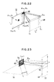
- Fig. 22 shows the deflecting function of the phase distribution display section 12 for performing a stereoscopic display of an image having a parallax in the horizontal direction by using divided images.
- Pixels which are long in the vertical direction are arranged in the phase display section 12.
- stripe regions which are long in the vertical direction are arranged in the virtual opening 48 in the horizontal direction.
- S f an arbitrary virtual opening region is expressed by S f .
- the 2-dimensional image is now divided in the vertical direction into stripe images which are long in the horizontal direction.
- the 1-pixel phase display section 46 at the right upper corner of the phase display section 12 the light from the corresponding pixel PIN is deflected to the regions S 11 to S ln of the top row of the virtual opening on the basis of the image division.
- the light is also deflected to the regions of the second row of the virtual opening 48.
- all of the 1-pixel phase display section 46 arranged in the vertical direction by the phase display section 12 are deflected in the same direction, they have the same phase distribution.
- the phase distributions of a plurality of 1-pixel display section 46 arranged in the vertical direction of the phase display section 12 can be handled as one phase distribution, the corresponding pixels are expressed by P 1 to P N in the vertical direction.
- Fig. 23 shows a calculating method of a phase distribution to realize the deflecting function shown in Fig. 22.
- a calculating method of a phase distribution in the 1-pixel phase display section 46 of the corresponding pixel P is shown with respect to the relation with the region S f of one virtual opening 48.
- a horizontal plane 56 which is perpendicular to the 1-pixel phase display section 46 and the virtual opening 48 is set.
- a plurality of virtual point light source 50 are arranged in the horizontal direction on the virtual opening 48 along the horizontal plane 56.
- the virtual reference light 52 is also set.
- phase distributions are calculated by the equations (3) and (4) every pixels 54 for phase display constructing the 1-pixel phase display section 46 with respect to all of the virtual point light sources 50.
- the 2-dimensional image data is the same as that in Fig. 21.
- a plurality of 2-dimensional image data G 1 to G n in the case where the virtual opening regions S 1 to S n were seen as visual points are prepared and time-divisionally displayed. Therefore, the virtual openings 48 shown in Fig. 22 change in the horizontal direction with the elapse of time in association with the switching of the 2-dimensional image data G 1 to G n . Accordingly, the calculation of phase distributions in Fig. 23 is executed with respect to the virtual opening regions whose positions change with the elapse of time in association with the switching of the 2-dimensional images G 1 to G n .
- phase distributions ⁇ j,1 to ⁇ l>j,n are calculated so as to deflect the lights from the pixels into the virtual openings 48 of the different regions S 1 to S n in correspondence to the 2-dimensional image display by the time-division. Consequently, as shown in Fig. 24, the phase distribution data which is used by the time-divisional display of every corresponding pixel is stored in the phase distribution storing table in case of an image having a parallax in the horizontal direction.
- a Lenticular lens 112 is provided as an optical device having a visible region enlarging function in the vertical direction. The image is diffused in the vertical direction, thereby producing the visible region 45.
- Fig. 26 shows a construction of a display apparatus of the first embodiment of a stereoscopic display apparatus of the invention.
- This embodiment is characterized in that a liquid crystal display is used as a 2-dimensional image display section 10 and a liquid crystal display is also used as a phase distribution display section 12.
- the liquid crystal display used as a 2-dimensional image display section 10 has the pixels of the number which are necessary to display 2-dimensional images and changes a transmission light amount of the incident reproduction light.
- the 2-dimensional image having parallaxes in the horizontal and vertical directions shown in Fig. 17 or the 2-dimensional image having a parallax in only the horizontal direction shown in Fig. 21 is displayed in the 2-dimensional image display section 10.
- Each of phase cells 64 of the liquid crystal display which is used in the phase distribution display section 12 has a very small pixel size such as 1.0 ⁇ m as partially enlargedly shown in Fig. 26 as compared with one pixel cell 62 of the 2-dimensional image display section 10.
- the phase distribution data in Fig. 16 is supplied and phase information (interference fringe) is displayed in such a micropixel of the phase display section 12.
- the phase distribution data shown in Fig. 20 is supplied and phase information (interference fringe) is displayed.
- the phase display section 12 accordingly, modulates the light from the 2-dimensional display section 10, thereby diffracting the light toward a predetermined virtual opening portion.
- Fig. 27 shows a whole construction of a display apparatus 58 with which the 2-dimensional image display section 10 and the phase distribution display section 12 shown in Fig. 26 are integrated.
- the display sections 12 and 10 are overlapped in the visual recognizing direction and the phase cells 64 are arranged in a matrix form.
- the phase cell 64 is constructed by pixels 66 for phase display which were further finely divided and a driving circuit 68 to drive the pixels 66.
- the pixel cells 62 of the 2-dimensional image display section construct one pixel 70 for displaying a 2-dimensional image. Adriving circuit 72 is provided in the cell 70.
- address lines extending in the horizontal direction are indicated by X1 to Xn and address lines extending in the vertical direction are shown by Y1 to y n .
- Fig. 28 shows a detailed structure of the display apparatus 58 in Fig. 27 with respect to four cells as an example.
- the lower layer of the display apparatus 58 constructs a liquid crystal display as a 2-dimensional image display section 10 and the upper layer constructs a liquid crystal display as a phase distribution display section 12.
- Driving circuits 68-11 to 68-22 are formed in the pixel electrodes 76-11 to 76-22. Further, address lines 78-1 and 78-2 of x, and X2 and signal lines 80-1 and 80-2 of y 1 and Y2 are arranged around the pixel electrodes 76-11 to 76-22.
- a glass substrate 82 in which a common electrode 84 is formed on the lower surface is arranged on the upper side of the 2-dimensional image display section 10.
- a liquid crystal is interposed between the glass substrates 74 and 84 shown in the diagram so as to sandwich the upper and lower surfaces by deflecting plates (PL), thereby obtaining a structure of the liquid crystal display as a 2-dimensional image display section 10.
- a common electrode 86 is provided on the upper side of a common glass substrate 82, and cell electrode sections 66-11 to 66-22 are further formed on the lower surface side of a top glass substrate 88.
- micro pixel electrodes 90 are two-dimensionally arranged and a gate switch 92, a decoding circuit 94, and a signal generating circuit 96 are formed as a driving circuit.
- Driving circuits 72-11 to 72-22 are formed in the cell electrode portions 66-11 to 66-22 of the glass substrate 88.
- address lines 98-1 and 98-2 shown by X1 and x 2 and signal lines 100-1 and 100-2 indicated by y 1 and Y2 are arranged for the glass substrate 88.
- the phase distribution display section 12 can realize a liquid crystal display by interposing a liquid crystal between the glass substrates 82 and 88 so as to be sandwiched by deflecting plates (PL).
- PL deflecting plates
- a ne- matic liquid crystal is used as a liquid crystal which is used in each of the display sections 10 and 12.
- the liquid crystal on the side of the phase distribution display section 12 has a homogeneous orientation.
- the cells on the horizontal line are turned on by the address lines 98-1 and 98-2 in the x direction and the phase distribution signals are given to the cells by the signal lines 100-1 and 100-2 in the y direction, thereby driving the phase distribution display section 12.
- a reproduction light is inputted from the side of the glass substrate 74 of the lower layer.
- the liquid crystal display as a 2-dimensional image display section 10 since a deflecting angle changes in dependence on the inputted pixel signal, a transmission amount of the light can be controlled.
- the deflecting direction can be controlled by changing the phase.
- Fig. 29 shows the second embodiment in which a 2-dimensional image having a parallax in the horizontal direction is further divided and an image type holographic stereogram having a parallax in the horizontal direction is stereoscopically displayed.
- the 2-dimensional image display section 10 is constructed by the liquid crystal display and the phase distribution display section 12 is also constructed by a liquid crystal display.
- the 2-dimensional image display section 10 can use the same liquid crystal display as that shown in the first embodiment of Fig. 26.
- the phase distribution display section 12 can use the liquid crystal display in which small pixels are arranged in the horizontal direction and large pixels are arranged in the vertical direction. A pixel size in the vertical direction is substantially equal to the pixel size of the 2-dimensional image display section 10.
- the Lenticular lens 112 in which a plurality of cylindrical lenses are arranged is provided as an optical device having a visible region enlarging function in the vertical direction, thereby enlarging the visible region in the vertical direction.
- Fig. 30 shows a visual recognizing range of a solid image in the second embodiment.
- the display light from the 2-dimensional image display section 10 which was diffused in only the horizontal direction by the phase distribution display section 12 is enlarged in the vertical direction of the visible region 45 by, for example, the Lenticularlens 112 as a unidirectional diffusing screen. Therefore, the observercan recognize a solid image by seeing two 2-dimensional images of different visual point positions when they are seen from, for instance, a virtual opening region A and another virtual opening region A i+k as after-image displays by the time-division.
- Fig. 31 is an explanatory diagram showing a whole construction of a display apparatus comprising the 2- dimensional image display section 10 and the phase distribution display section 12 in the second embodiment of Fig. 29.
- the 2-dimensional image display section 10 side is the same as that in the first embodiment of Fig. 27.
- a phase cell 64 with regard to the phase distribution display section 12, pixels 102 for phase display which are short in the horizontal direction and each of which has almost the same size as that of the pixel 70 for displaying a 2-dimensional image are arranged in the vertical direction, and a driving circuit 104 is further integratedly provided.
- Fig. 32 shows a specific structure of a display apparatus 60 in Fig. 31 with respect to four cells.
- the 2- dimensional image display section 10 of the lower layer is substantially the same as that in the first embodiment of Fig. 28.
- a plurality of pixel electrodes 106 each of which is short in the horizontal direction and has a width of one pixel in the vertical direction are arranged in each of four cell electrode sections 102-11 to 102-22 as shown in the cell electrode section 102-22 which was particularly shown in the diagram.
- a gate switch 108, a decoding circuit 110, and a signal generating circuit 114 are further provided as a driving circuit.
- a liquid crystal sandwiched by upper and lower deflecting plates (PL) is interposed between the intermediate glass substrate 82 and an upper glass substrate 105. Further, the Lenticular lens 112 shown in Fig. 29 is disposed on the glass substrate 105 of the upper layer.
- all of the cells arranged in the vertical direction have the same phase distribution. Therefore, the cells on the same vertical line are turned on by the signal lines 100-1 and 100-2 extending in the vertical direction and the phase distribution information is simultaneously given to each cell by a signal line 116 in the Y direction, thereby driving the phase distribution display section 12.
- Fig. 33 is an explanatory diagram showing a modification of the second embodiment of the invention and is characterized in that a 1-dimensional liquid crystal device is used as a 2-dimensional image display section and a phase distribution display section.
- the optical system comprises: a 1-dimensional image display 120; a 1-dimensional phase display 122; a galvano mirror 124; a lens system 126; and the Lenticular lens 112.
- the 1-dimensional image display 120, the 1-dimensional phase display 122, and the galvano mirror 124 are controlled by a display control section 130.
- Adivided 2-dimensional image storing table 132 and a 1-dimensional phase distribution storing table 134 are provided for the display control section 130. As shown in Fig.
- Fig. 35 picks up and shows the optical system in Fig. 33.
- Adisplay light from each pixel of the 1-dimensional image display 120 is subjected to the deflection by the phase distribution displayed in the corresponding 1- dimensional phase display 122 and enters the galvano mirror 124.
- the 1-dimensional display image scanned in the vertical direction by the galvano mirror 124 is formed onto the Lenticular lens 112 and the visible region is enlarged in the vertical direction, so that an observer 42 can see a solid image.
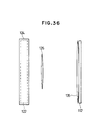
- Fig. 36 shows a plan view of Fig. 35.
- the 1-dimensional phase display 122 and the 1-dimensional image display 120 are located below the galvano mirror 124.
- Acylindrical lens 135 having an optical power in only the horizontal direction is further arranged behind the Lenticular lens 112.
- Fig. 37 shows the vertical scan of the galvano mirror 124 in Fig. 35.
- a deflecting operation to the lens 126 is performed within a range from a virtual image 122-1 to a virtual image 122-3.
- the light is inputted as a scan light in the vertical direction by the lens 126 into the Lenticular lens 112 having the cylindrical lens 135 on the rear side.
- Fig. 38 shows the third embodiment of the invention using an acoustic optical device (AOM device) as a phase distribution display.
- AOM device acoustic optical device
- the same 2-dimensional image display section 10 as that in each of the first and second embodiments is used.
- an acoustic optical device 136 is provided subsequent to the 2-dimensional image display section 10.
- the acoustic optical device 136 is made of a crystal of Ta0 2 and has a structure such that a transducer 138 as an acoustic vibrator for converting an electric signal into an acoustic signal is provided on one side and an absorbing material 140 for absorbing a sound wave is provided on the opposite side.
- the acoustic optical device 136 generates a wave which is propagated in the horizontal direction which is determined by the arranging position of the transducer 138 and generates a 1-dimensional phase distribution similar to that in the second embodiment shown in Fig. 29.
- the Lenticular lens 112 is provided to enlarge the visible region in the vertical direction.
- Fig. 39 is a time chart showing the driving operation of the acoustic optical device 136 in Fig. 38. That is, an electric signal of a frequency distribution B1' is given to the transducer 138 at time t1, thereby producing a corresponding spatial frequency distribution B1 in the acoustic optical device 136 as shown in Fig. 40.
- the spatial frequency distribution B1 for example, the tight from a pixel 144-1 is diffracted at a desired angle 8 1 and the light from the pixel 144-1 can be seen from a certain virtual opening.
- An electric signal of a frequency distribution B2' is subsequently given to the transducer 138 at a timing of time t2 in Fig.
- the light from the pixel 144-1 is emitted at an angle of 0 2 due to the refractive index distribution by the spatial frequency distribution B2 in the acoustic optical device 136.
- the light from the pixel 114-1 can be seen from a virtual opening different from that at time t1. In this instance, since the refractive index distribution of the spatial frequency distribution B1 produced at time t1 has been moved to the corresponding position of a next pixel 144-2, so that the light from the pixel 144-2 is emitted at an angle 8 1 .
- both of the lights from the pixels 144-1 and 144-2 can be seen at the position where the laser beams emitted at the angles 8 1 and 0 2 are overlapped.
- the refractive index distribution which is produced on the acoustic optical device 136 moves with the elapse of time, since the light from a micro pixel is seen, by reconstructing the images in accordance with the synchronization depending on the pixel array, a flow of image doesn't occur.
- one 2-dimensional image can be seen at the same position of the virtual opening.
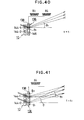
- Fig. 42 shows an embodiment including an illuminating section of the third embodiment using an acoustic optical device.
- the light from a light source 148 of a semiconductor laser is converted into the parallel light by an aspheric mirror 150 and enters a photoconductive plate 152.
- Half mirrors 154-1 to 154-3 and a mirror 156 are obliquely arranged in the photoconductive plate 152, thereby allowing the reproduction lights to obliquely enter the liquid crystal display as a 2-dimensional image display section 10 as shown by arrows of broken lines. Reflectances of the half mirrors 154-1 to 154-3 are different in order to equalize the intensities of incident lights.
- a large device cannot be obtained because of a difference of the materials which are used in the acoustic optical device
- small acoustic optical devices are combined, thereby realizing an acoustic optical device of a large area.
- a sound wave from the transducer 138 can be also propagated to the next acoustic optical device 136 by an acoustic transferring material 158.
- a plurality of acoustic optical devices 136 each having the transducer 138 can be also combined.
- Fig. 44 shows a fundamental construction of the fourth embodiment according to the invention.
- the pixels constructing the 2-dimensional image are diffracted so as to be seen from the corresponding virtual opening, such a function is substantially the same as the directional diffusing function for deflecting the laser beam and for diffusing the light with a certain extent. Therefore, in the fourth embodiment, an image type holographic stereogram is formed by a deflector 160 and a directional diffusing functional device 162 in place of the phase display section.
- a solid image can be recognized by using a parallax of both eyes and a vergence of two eyes.
- Fig. 45 shows a state of a stereoscopic display of Fig. 44.
- the light from each pixel of the 2-dimensional image display 10 is deflected in the horizontal direction by a combination of the deflector 160 and the directional diffusing functional device 162. Further, the light is diffused in the vertical direction by the Lenticular lens 112 provided as necessary. Therefore, in the visible range 45 in which the virtual opening is located, the left eye of the observer 42 observers the 2-dimensional image seen from the virtual opening area A;, while the left eye observes the 2-dimensional image seen from the virtual opening area A ;+k . Thus , a solid image due to the parallax between both eyes and a vergence between both eyes can be recognized.
- Fig. 46 shows a display apparatus 170 with which the deflector 160 and the directional diffusing functional device 162 shown in Fig. 44 are integrated.
- An internal structure when it is seen as a plan view is taken out and shown in Fig. 47.
- a light emitting device 174, a galvano mirror 178 which is driven by a motor 176, an a directional diffusing functional device 180 execute the display of one pixel by a group in a lump.
- the light emitted from the light emitting device 174 is deflected by the galvano mirror 178 and enters the directional diffusing functional device 180. Practically speaking, such a light enters a thin diffusing plate.
- the light which entered the directional diffusing functional device using a thin diffusing plate is slightly diffused onto the line of the incident laser beam and is emitted as shown in Fig. 48.
- the light emitted from the directional diffusing functional device 180 is extended toward the virtual opening.
- the observer42 can see the 2-dimensional image at the position of the virtual opening by the light emitted from the display apparatus 170.
- a solid image can be perceived by seeing different images by the right and left eyes.
- Fig. 49 shows an embodiment in which a deflecting function was realized by changing the relative positions of the light emitting device and the lens.
- Two pixels are picked up and shown in the diagram, when considering the pixels on the lower side, piezoelectric devices 182 are attached to a supporting member 185, a lever 186 supported by a fulcrum 184 is attached, and a light emitting device 188 provided for the lever 186 can be moved in the direction perpendicular to the optical axis by the driving of the piezoelectric device 182.
- a lens 190 and the directional diffusing functional device 180 using a thin diffusing plate are arranged in front of the light emitting device 188. Therefore, by changing the relative position of the light emitting device 188 for the lens 190 by the driving of the piezoelectric device 182, the light from the light emitting device 188 can be deflected.
- FIG. 50 An embodiment of Fig. 50 is characterized in that the light emitting device 188 is attached to the supporting member 185 and a lever 194 having the fulcrum 184 is driven by the piezoelectric device 182 and the lens 190 is moved, thereby deflecting the light from the light emitting device 188.
- a lens 198 to enlarge a deflecting angle is provided in addition to the lens 190 and the lens 198 on the light emitting device 188 side is finely moved by the driving of the lever 186 by the piezoelectric device 182, thereby performing the deflecting operation.
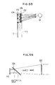
- Fig. 52 shows an embodiment in which the deflecting direction is controlled on the basis of a difference of the light emitting positions and the virtual opening position at which a 2-dimensional image can be observed is controlled. That is, Fig. 52 shows a plan view.
- An LED array 200 is used as means for controlling the deflecting direction due to a difference of the light emitting positions.
- the LED array 200 has a line-shape which is long in the vertical direction and each LED is densely arranged in the horizontal direction. Therefore, in the LED array 200, the light emitting point moves in the horizontal direction with the elapse of time.
- a Fresnel lens 202 of a focal distance of 2F is arranged in close vicinity to the LED array 200.
- a Fresnel lens 204 having a focal distance F is arranged at a position of the focal distance of 2F from the Fresnel lens 202.
- the 2-dimensional image display 10 is arranged in close vicinity to the Fresnel lens 204.
- the light irradiated to the Fresnel lens 204 passes through the 2-dimensional image display 10 and is formed as an image in the region of a corresponding virtual opening 210 in the visible range 45. Since the light emitting position of the LED array 200 has a certain region as a light source, the image forming position in the visible range 45 also has a certain region and such a region functions as a virtual opening 210. A2-dimensional image can be seen at this position.
- FIG. 53 An embodiment of Fig. 53 is characterized in that a Lenticular lens 206 and a liquid crystal shutter 208 are provided in place of the LED array 200 in Fig. 52. Namely, the light from the light source is converged by the Lenticular lens 206 and is inputted to the liquid crystal shutter 208. A slit-like opening which is narrow in the horizontal direction and is long in the vertical direction is formed by the liquid crystal shutter 208. This opening is moved in the horizontal direction with the elapse of time.
- Fig. 54 is characterized in thatthe directional diffusing functional device 180 is further provided subsequent to the 2-dimensional image display 10 in the embodiment of Fig. 52, thereby preventing that the virtual opening 210 is limited by the size of light source.
- a Lenticular lens 218 is provided as a deflector in correspondence to a pixel 424 of the 2-dimensional image display 10.
- a plurality of display pixels 424 of the 2-dimensional image display 10 are made correspond to one Lenticular lens and those pixels are arranged at the focal point positions of the Lenticular lens 218.
- the direction of the light is determined by the position of the pixel as a picture element and the deflecting direction can be controlled.
- a mask 216 is provided subsequent to the Lenticular lens 218. A crosstalk from the adjacent pixel is eliminated by the mask 216. Further, the Lenticular lens 112 can be also provided as necessary.
- Fig. 56 shows the formation of a hologram in the case where a hologram having a fixed interference fringe was used as a directional diffusing functional device in the fourth embodiment.
- Fig. 57 shows a reconstructing state.
- the light from a diffusing plate 222 is transmitted as an object wave through a half mirror 224.
- the reference light is inputted from the perpendicular direction into the half mirror 224 and is reflected and a hologram 220 is formed by an interference exposure by the object wave and the reference wave.
- a deflecting state in which the setting position of the diffusing plate 222 upon formation is set to visible range 45-1 can be obtained.
- a visible range 45-2 different from the visible range 45-1 can be set as shown by a broken line.
- an LD array 225 in which laser diodes are two-dimensionally arranged can be also used as shown in Fig. 58.
- one laser diode (LD) corresponds to one of the pixels of the 2-dimensional image in the first to third embodiments.
- a plurality of laser diodes correspond to one of the pixels of the 2-dimensional image in the fourth embodiment.
- Fig. 59 shows an embodiment of a stereoscopic display apparatus of the invention which can display a color image and relates to a color display by the time-division as an example.
- the 2-dimensional image display section 10, phase distribution display section 12, and Lenticular lens 112 are the same as those in the second embodiment.
- a light source is provided every color component of R, G and B. Namely, semiconductor lasers are provided as a light source 226 for a red light (R), a light source 228 for a green light (G), and a light source 230 for a blue light (B).
- the color components of R, G, and B from the light sources 226, 228, and 230 are reflected by dichroic mirrors 232 and 234 and enter an aspheric mirror 236 and are converted into the parallel lights.
- the parallel lights are reflected by the same half mirrors 154-1 to 154-3 and mirror 156 as those shown in Fig. 42 and are irradiated to the 2-dimensional image display section 10.
- Fig. 60 shows a driving timing by the time-division of the RGB images for the light sources of RGB in Fig. 59 and the 2-dimensional image display section 10.
- Fig. 61 shows an embodiment of a stereoscopic display apparatus for displaying a color solid image by the space-division.
- the apparatus comprises the 2-dimensional image display section 10, phase distribution display section 12, and Lenticular lens 112 and uses a white light 242 as a light source for the display section 10.
- Figs. 62A and 62B show pixel constructions of the 2-dimensional image display section 10 and phase distribution display section 12 which are used for displaying a color solid image by the space-division in Fig. 61.
- Fig. 62A shows the 2-dimensional image display section 10.
- a filter 244 for R, a filter 246 for G, and a fitter 248 for B are provided for the pixels.
- the RGB filters are repetitively arranged in the horizontal and vertical directions.
- Fig. 62B shows a cell arrangement of the phase distribution display 12.
- a cell 250 for R, a cell 252 for G, and a cell 254 for B are arranged in one-to-one correspondence to each filter of RGB in the 2-dimensional image display section 10 in Fig. 62A.
- Fig. 64A shows an arrangement of the filters 244, 246, and 248 for RGB by the color solid image display by the space division in case of using a phase distribution display for deflecting the light in only the horizontal direction.
- Fig. 64B shows an arrangement of the cells 250,252, and 254 for R, G, and B in the phase distribution display 12 corresponding to Fig. 64A.
- the RGB filters of the pixels provided in the 2-dimensional image display section 10 shown in Figs. 62A, 62B, 64A, and 64B receive the irradiation of the white light or the light including bright line spectra of R, G, and B and extract the RGB components and emits the lights of the intensities according to the control intensities of the liquid crystal pixels.
- an image type holographic stereogram there is no need to perform the phase calculation with respect to each of the 2-dimensional images of different visual directions.
- a solid image can be allowed to be recognized as an after-image. Therefore, since there is no need to perform the calculation of the phase distribution upon reconstruction display, the construction of the apparatus can be simplified.
- Embodiments of the invention can cope with the high-speed display in a moving image display or the like. The calculation load on the computer can be obviously remarkably reduced.
Landscapes
- Physics & Mathematics (AREA)
- General Physics & Mathematics (AREA)
- Optics & Photonics (AREA)
- Holo Graphy (AREA)
- Testing, Inspecting, Measuring Of Stereoscopic Televisions And Televisions (AREA)
Applications Claiming Priority (3)
| Application Number | Priority Date | Filing Date | Title |
|---|---|---|---|
| JP260924/92 | 1992-09-30 | ||
| JP26092492 | 1992-09-30 | ||
| JP4260924A JPH06110374A (ja) | 1992-09-30 | 1992-09-30 | 立体表示装置 |
Publications (3)
| Publication Number | Publication Date |
|---|---|
| EP0590832A2 true EP0590832A2 (de) | 1994-04-06 |
| EP0590832A3 EP0590832A3 (en) | 1996-05-08 |
| EP0590832B1 EP0590832B1 (de) | 2002-05-15 |
Family
ID=17354659
Family Applications (1)
| Application Number | Title | Priority Date | Filing Date |
|---|---|---|---|
| EP93307334A Expired - Lifetime EP0590832B1 (de) | 1992-09-30 | 1993-09-16 | Stereoskopisches Darstellungsgerät |
Country Status (5)
| Country | Link |
|---|---|
| US (2) | US5497189A (de) |
| EP (1) | EP0590832B1 (de) |
| JP (1) | JPH06110374A (de) |
| CA (1) | CA2106244C (de) |
| DE (1) | DE69331925T2 (de) |
Cited By (4)
| Publication number | Priority date | Publication date | Assignee | Title |
|---|---|---|---|---|
| EP0650301A3 (de) * | 1993-10-26 | 1995-07-12 | Matsushita Electric Industrial Co Ltd | Vorrichtung zur dreidimensionalen Bildanzeige. |
| WO2001031384A1 (en) * | 1999-10-27 | 2001-05-03 | Gregory Michael Orme | Improvements in three dimensional processing techniques and multi-dimensional devices |
| EP1233296A3 (de) * | 1994-03-18 | 2002-10-16 | Fujitsu Limited | Vorrichtung zur stereoskopischen Anzeige |
| CN110275309A (zh) * | 2019-07-04 | 2019-09-24 | 京东方科技集团股份有限公司 | 偏振微透镜结构、显示装置及其驱动方法 |
Families Citing this family (37)
| Publication number | Priority date | Publication date | Assignee | Title |
|---|---|---|---|---|
| WO1996041331A1 (en) * | 1995-06-07 | 1996-12-19 | Gregory Barrington, Ltd. | Free-vision three-dimensional image with enhanced viewing |
| DE69735736T2 (de) * | 1996-01-31 | 2006-11-02 | Canon K.K. | Stereoskopische Bilddarstellungsvorrichtung mit verbreitertem Beobachtungsfeld |
| US6009188A (en) | 1996-02-16 | 1999-12-28 | Microsoft Corporation | Method and system for digital plenoptic imaging |
| WO1997035223A1 (en) | 1996-03-15 | 1997-09-25 | Retinal Display Cayman Limited | Method of and apparatus for viewing an image |
| US6304263B1 (en) | 1996-06-05 | 2001-10-16 | Hyper3D Corp. | Three-dimensional display system: apparatus and method |
| US6259450B1 (en) | 1996-06-05 | 2001-07-10 | Hyper3D Corp. | Three-dimensional display system apparatus and method |
| GB9623682D0 (en) * | 1996-11-14 | 1997-01-08 | Philips Electronics Nv | Autostereoscopic display apparatus |
| US6088052A (en) * | 1997-01-08 | 2000-07-11 | Recherches Point Lab Inc. | 3D stereoscopic video display system |
| HUP9700348A1 (hu) * | 1997-02-04 | 1998-12-28 | Holografika E.C. | Eljárás és berendezés háromdimenziós kép megjelenítésére |
| US6157424A (en) * | 1998-03-30 | 2000-12-05 | Dimension Technologies, Inc. | 2D/3D imaging display |
| US6073854A (en) * | 1998-05-21 | 2000-06-13 | Lti Corporation | Telephone card or the like using lenticular lens material |
| KR100304784B1 (ko) * | 1998-05-25 | 2001-09-24 | 박호군 | 편광과광띠를이용한다자시청용3차원영상표시장치 |
| WO2000007066A1 (en) | 1998-07-29 | 2000-02-10 | Digilens, Inc. | In-line infinity display system employing one or more switchable holographic optical elements |
| AU6143199A (en) * | 1998-09-14 | 2000-04-03 | Digilens Inc. | Holographic illumination system and holographic projection system |
| US6339486B1 (en) | 1998-10-16 | 2002-01-15 | Digilens, Inc. | Holographic technique for illumination of image displays using ambient illumination |
| US6421109B1 (en) | 1998-10-16 | 2002-07-16 | Digilens, Inc. | Method and system for display resolution multiplication |
| US6850210B1 (en) * | 1998-11-12 | 2005-02-01 | Stereographics Corporation | Parallax panoramagram having improved depth and sharpness |
| US6678078B1 (en) | 1999-01-07 | 2004-01-13 | Digilens, Inc. | Optical filter employing holographic optical elements and image generating system incorporating the optical filter |
| US6504629B1 (en) | 1999-03-23 | 2003-01-07 | Digilens, Inc. | Method and apparatus for illuminating a display |
| US6507419B1 (en) | 1999-03-23 | 2003-01-14 | Digilens, Inc. | Illumination system using optical feedback |
| WO2001011895A1 (en) | 1999-08-04 | 2001-02-15 | Digilens, Inc. | Apparatus for producing a three-dimensional image |
| RU2158949C1 (ru) * | 1999-09-02 | 2000-11-10 | Общество с ограниченной ответственностью "НЕЙРОК" | Способ воспроизведения изображения объекта |
| US6717728B2 (en) | 1999-12-08 | 2004-04-06 | Neurok Llc | System and method for visualization of stereo and multi aspect images |
| US6424437B1 (en) | 2000-10-10 | 2002-07-23 | Digilens, Inc. | Projection display employing switchable holographic optical elements |
| US6759998B2 (en) * | 2001-10-19 | 2004-07-06 | Intel Corporation | Method and apparatus for generating a three-dimensional image on an electronic display device |
| WO2003058979A2 (en) * | 2002-01-04 | 2003-07-17 | Neurok Llc | Three-dimensional image projection employing retro-reflective screens |
| GB2390948A (en) * | 2002-07-17 | 2004-01-21 | Sharp Kk | Autostereoscopic display |
| GB0400373D0 (en) * | 2004-01-09 | 2004-02-11 | Koninkl Philips Electronics Nv | A three-dimensional display |
| US7522236B2 (en) * | 2005-09-23 | 2009-04-21 | Apple Inc. | Cosmetically uniform reflective border area in a transflective display |
| TWI292833B (en) * | 2006-05-04 | 2008-01-21 | Ind Tech Res Inst | Image display apparatur |
| CN101226325B (zh) | 2008-02-03 | 2010-06-02 | 李志扬 | 基于随机相长干涉的三维显示方法及装置 |
| WO2010120260A1 (en) * | 2009-04-13 | 2010-10-21 | Hewlett-Packard Development Company, L.P. | Dynamically reconfigurable holograms for generating color holographic images |
| WO2009136218A1 (en) * | 2008-05-06 | 2009-11-12 | Microvision Inc. | An apparatus for displaying 3 d images |
| DE102008043621A1 (de) * | 2008-11-10 | 2010-05-12 | Seereal Technologies S.A. | Holografisches Farbdisplay |
| CN105487239B (zh) * | 2015-11-13 | 2018-03-02 | 苏州苏大维格光电科技股份有限公司 | 指向性彩色滤光片和裸眼3d显示装置 |
| CN107765438B (zh) * | 2016-08-18 | 2020-09-15 | 群睿股份有限公司 | 影像显示装置及影像显示方法 |
| CN109991739B (zh) * | 2017-12-29 | 2024-09-10 | 深圳点石创新科技有限公司 | 车载抬头显示器 |
Family Cites Families (5)
| Publication number | Priority date | Publication date | Assignee | Title |
|---|---|---|---|---|
| GB1384963A (en) * | 1972-04-28 | 1975-02-26 | Konishiroku Photo Ind | Method of reproducing images |
| US5036385A (en) * | 1986-03-07 | 1991-07-30 | Dimension Technologies, Inc. | Autostereoscopic display with multiple sets of blinking illuminating lines and light valve |
| US4783133A (en) * | 1986-08-26 | 1988-11-08 | Saginaw Valley State University | Method and apparatus for forming a hologram from incoherent light |
| US4964684A (en) * | 1988-12-28 | 1990-10-23 | John Iovine | Holographic image recording using liquid crystal |
| JPH05122733A (ja) * | 1991-10-28 | 1993-05-18 | Nippon Hoso Kyokai <Nhk> | 3次元画像表示装置 |
-
1992
- 1992-09-30 JP JP4260924A patent/JPH06110374A/ja active Pending
-
1993
- 1993-09-15 CA CA002106244A patent/CA2106244C/en not_active Expired - Fee Related
- 1993-09-16 DE DE69331925T patent/DE69331925T2/de not_active Expired - Fee Related
- 1993-09-16 EP EP93307334A patent/EP0590832B1/de not_active Expired - Lifetime
- 1993-09-23 US US08/125,660 patent/US5497189A/en not_active Expired - Lifetime
-
1996
- 1996-01-30 US US08/594,021 patent/US5696552A/en not_active Expired - Lifetime
Cited By (6)
| Publication number | Priority date | Publication date | Assignee | Title |
|---|---|---|---|---|
| EP0650301A3 (de) * | 1993-10-26 | 1995-07-12 | Matsushita Electric Industrial Co Ltd | Vorrichtung zur dreidimensionalen Bildanzeige. |
| US6057878A (en) * | 1993-10-26 | 2000-05-02 | Matsushita Electric Industrial Co., Ltd. | Three-dimensional picture image display apparatus |
| EP1233296A3 (de) * | 1994-03-18 | 2002-10-16 | Fujitsu Limited | Vorrichtung zur stereoskopischen Anzeige |
| WO2001031384A1 (en) * | 1999-10-27 | 2001-05-03 | Gregory Michael Orme | Improvements in three dimensional processing techniques and multi-dimensional devices |
| CN110275309A (zh) * | 2019-07-04 | 2019-09-24 | 京东方科技集团股份有限公司 | 偏振微透镜结构、显示装置及其驱动方法 |
| CN110275309B (zh) * | 2019-07-04 | 2021-12-28 | 京东方科技集团股份有限公司 | 偏振微透镜结构、显示装置及其驱动方法 |
Also Published As
| Publication number | Publication date |
|---|---|
| DE69331925T2 (de) | 2002-08-29 |
| US5696552A (en) | 1997-12-09 |
| US5497189A (en) | 1996-03-05 |
| DE69331925D1 (de) | 2002-06-20 |
| CA2106244C (en) | 1999-08-03 |
| EP0590832B1 (de) | 2002-05-15 |
| EP0590832A3 (en) | 1996-05-08 |
| JPH06110374A (ja) | 1994-04-22 |
| CA2106244A1 (en) | 1994-03-31 |
Similar Documents
| Publication | Publication Date | Title |
|---|---|---|
| US5696552A (en) | Stereoscopic display apparatus | |
| JP7418378B2 (ja) | 表示装置 | |
| US5926294A (en) | Three-dimensional image display device having an elementary hologram panel and method for manufacturing the elementary hologram panel | |
| US7843636B2 (en) | Image display method for a stereoscopic image | |
| US5561537A (en) | Stereoscopic display method and apparatus | |
| EP0900501B1 (de) | Verfahren und gerät zur darstellung dreidimensionaler bilder | |
| EP0899969B1 (de) | Dreidimensionales Bilderzeugungssystem und -gerät | |
| US5943166A (en) | Stereoscopic image display apparatus including a parallax barrier and an optical element including diffraction means | |
| US6940653B2 (en) | Radiation conditioning system | |
| US8220929B2 (en) | Three-dimensional image display apparatus | |
| CN108803295B (zh) | 大视场全息图的制作方法、显示系统及点阵光源 | |
| CN101449214B (zh) | 再现场景的全息投射装置 | |
| US20110043909A1 (en) | Three-dimensional image display apparatus | |
| JP2009288759A (ja) | 3次元像表示装置及び画像表示方法 | |
| US20060290777A1 (en) | Three-dimensional image display apparatus | |
| CN110531525B (zh) | 用于实现三维图像近眼显示的装置 | |
| WO2004051345A1 (ja) | 立体画像表示装置 | |
| WO2010016422A1 (ja) | 画像表示装置 | |
| EP1988420A1 (de) | Vorrichtung zur volumetrischen Anzeige | |
| JP5104063B2 (ja) | 3次元像表示装置 | |
| JP2007041504A (ja) | 3次元像表示装置 | |
| CN100462775C (zh) | 三维图像显示装置 | |
| JP2007199587A (ja) | 3次元像表示装置 | |
| JP2009290440A (ja) | 画像表示方法 | |
| JP2008151863A (ja) | 3次元像表示装置 |
Legal Events
| Date | Code | Title | Description |
|---|---|---|---|
| PUAI | Public reference made under article 153(3) epc to a published international application that has entered the european phase |
Free format text: ORIGINAL CODE: 0009012 |
|
| AK | Designated contracting states |
Kind code of ref document: A2 Designated state(s): DE FR GB |
|
| PUAL | Search report despatched |
Free format text: ORIGINAL CODE: 0009013 |
|
| AK | Designated contracting states |
Kind code of ref document: A3 Designated state(s): DE FR GB |
|
| 17P | Request for examination filed |
Effective date: 19960705 |
|
| 17Q | First examination report despatched |
Effective date: 19970403 |
|
| GRAG | Despatch of communication of intention to grant |
Free format text: ORIGINAL CODE: EPIDOS AGRA |
|
| GRAG | Despatch of communication of intention to grant |
Free format text: ORIGINAL CODE: EPIDOS AGRA |
|
| GRAH | Despatch of communication of intention to grant a patent |
Free format text: ORIGINAL CODE: EPIDOS IGRA |
|
| GRAH | Despatch of communication of intention to grant a patent |
Free format text: ORIGINAL CODE: EPIDOS IGRA |
|
| GRAA | (expected) grant |
Free format text: ORIGINAL CODE: 0009210 |
|
| AK | Designated contracting states |
Kind code of ref document: B1 Designated state(s): DE FR GB |
|
| PG25 | Lapsed in a contracting state [announced via postgrant information from national office to epo] |
Ref country code: FR Free format text: LAPSE BECAUSE OF FAILURE TO SUBMIT A TRANSLATION OF THE DESCRIPTION OR TO PAY THE FEE WITHIN THE PRESCRIBED TIME-LIMIT Effective date: 20020515 |
|
| REG | Reference to a national code |
Ref country code: GB Ref legal event code: FG4D |
|
| REF | Corresponds to: |
Ref document number: 69331925 Country of ref document: DE Date of ref document: 20020620 |
|
| EN | Fr: translation not filed | ||
| PLBE | No opposition filed within time limit |
Free format text: ORIGINAL CODE: 0009261 |
|
| STAA | Information on the status of an ep patent application or granted ep patent |
Free format text: STATUS: NO OPPOSITION FILED WITHIN TIME LIMIT |
|
| 26N | No opposition filed |
Effective date: 20030218 |
|
| PGFP | Annual fee paid to national office [announced via postgrant information from national office to epo] |
Ref country code: DE Payment date: 20060914 Year of fee payment: 14 |
|
| PG25 | Lapsed in a contracting state [announced via postgrant information from national office to epo] |
Ref country code: DE Free format text: LAPSE BECAUSE OF NON-PAYMENT OF DUE FEES Effective date: 20080401 |
|
| PGFP | Annual fee paid to national office [announced via postgrant information from national office to epo] |
Ref country code: GB Payment date: 20090916 Year of fee payment: 17 |
|
| GBPC | Gb: european patent ceased through non-payment of renewal fee |
Effective date: 20100916 |
|
| PG25 | Lapsed in a contracting state [announced via postgrant information from national office to epo] |
Ref country code: GB Free format text: LAPSE BECAUSE OF NON-PAYMENT OF DUE FEES Effective date: 20100916 |