EP0590846B1 - Processeur d'images pour détection et poursuite de cibles - Google Patents
Processeur d'images pour détection et poursuite de cibles Download PDFInfo
- Publication number
- EP0590846B1 EP0590846B1 EP93307464A EP93307464A EP0590846B1 EP 0590846 B1 EP0590846 B1 EP 0590846B1 EP 93307464 A EP93307464 A EP 93307464A EP 93307464 A EP93307464 A EP 93307464A EP 0590846 B1 EP0590846 B1 EP 0590846B1
- Authority
- EP
- European Patent Office
- Prior art keywords
- images
- image
- intensity
- simulated
- producing
- Prior art date
- Legal status (The legal status is an assumption and is not a legal conclusion. Google has not performed a legal analysis and makes no representation as to the accuracy of the status listed.)
- Expired - Lifetime
Links
Images



Classifications
-
- G—PHYSICS
- G01—MEASURING; TESTING
- G01S—RADIO DIRECTION-FINDING; RADIO NAVIGATION; DETERMINING DISTANCE OR VELOCITY BY USE OF RADIO WAVES; LOCATING OR PRESENCE-DETECTING BY USE OF THE REFLECTION OR RERADIATION OF RADIO WAVES; ANALOGOUS ARRANGEMENTS USING OTHER WAVES
- G01S3/00—Direction-finders for determining the direction from which infrasonic, sonic, ultrasonic or electromagnetic waves, or particle emission, not having a directional significance, are being received
- G01S3/78—Direction-finders for determining the direction from which infrasonic, sonic, ultrasonic or electromagnetic waves, or particle emission, not having a directional significance, are being received using electromagnetic waves other than radio waves
- G01S3/782—Systems for determining direction or deviation from predetermined direction
- G01S3/785—Systems for determining direction or deviation from predetermined direction using adjustment of orientation of directivity characteristics of a detector or detector system to give a desired condition of signal derived from that detector or detector system
- G01S3/786—Systems for determining direction or deviation from predetermined direction using adjustment of orientation of directivity characteristics of a detector or detector system to give a desired condition of signal derived from that detector or detector system the desired condition being maintained automatically
- G01S3/7864—T.V. type tracking systems
- G01S3/7865—T.V. type tracking systems using correlation of the live video image with a stored image
-
- G—PHYSICS
- G06—COMPUTING OR CALCULATING; COUNTING
- G06V—IMAGE OR VIDEO RECOGNITION OR UNDERSTANDING
- G06V10/00—Arrangements for image or video recognition or understanding
- G06V10/20—Image preprocessing
- G06V10/255—Detecting or recognising potential candidate objects based on visual cues, e.g. shapes
-
- G—PHYSICS
- G01—MEASURING; TESTING
- G01S—RADIO DIRECTION-FINDING; RADIO NAVIGATION; DETERMINING DISTANCE OR VELOCITY BY USE OF RADIO WAVES; LOCATING OR PRESENCE-DETECTING BY USE OF THE REFLECTION OR RERADIATION OF RADIO WAVES; ANALOGOUS ARRANGEMENTS USING OTHER WAVES
- G01S13/00—Systems using the reflection or reradiation of radio waves, e.g. radar systems; Analogous systems using reflection or reradiation of waves whose nature or wavelength is irrelevant or unspecified
- G01S13/66—Radar-tracking systems; Analogous systems
- G01S13/72—Radar-tracking systems; Analogous systems for two-dimensional [2D] tracking, e.g. combination of angle and range tracking, track-while-scan radar
- G01S13/723—Radar-tracking systems; Analogous systems for two-dimensional [2D] tracking, e.g. combination of angle and range tracking, track-while-scan radar by using numerical data
- G01S13/726—Multiple target tracking
Definitions
- This invention relates to an image processor for target detection and tracking, and more particularly, to target detection and tracking for a plurality of targets.
- a common surveillance problem is encountered when tracking a potentially large number of targets based on measurements originating from a potentially large number of sensors which may be separated over long distances.
- the sensors provide information regarding parameters for the location and the change in location of the targets to a central location relative to the sensor's position.
- Such parameters may include bearing, range, bearing rate, velocity, or position.
- the measurements are corrupted by random noise and deterministic bias, both of which may vary.
- Multitarget, Multisensor tracking Advanced Applications , by Y.Bar-Shalom, ed., published in 1990 by Artech House, Inc.
- multi-hypothesis tracking an association is first assumed between the measurements collected and the potential targets and for every assumption, i.e. hypothesis, the target positions are updated using the measurements in question as input signals to a filter, such as a Kalman filter.
- the resulting error between the measurement and the filtered track is used to rank each hypothesis and as new measurements are collected the process is repeated.
- multisensor tracking problem often proves intractable due to the multitude of detections, the inaccuracy of the sensor measurements, and the possibility of spurious detections, such as caused by multipath or other deterministic and/or random affects.
- association probability may be determined in accordance with specific closed form analytical expressions, such as those used for the Kalman filter, as disclosed in “Tracking in a Cluttered Environment with Probabilistic Data Association,” by Y.Bar-Shalom and E. Tse, published in Automatica , Vol. 11, pp. 451-460 (1973), and in “Sonar Tracking of Multiple Targets Using Joint Probabilistic Data Association,” by T. Fortmann, Y.Bar-Shalom, and M. Scheffe, published in IEEE Journal of Oceanic Engineering , Vol. OE8, No.
- EP 0 482 521 A2 relates to similar problems in a different technical field. Particularly, it relates to a television conference system for transmitting images of the faces of individuals participating in a television conference.
- the system is used for automatic control of the direction of a television camera placed on a camera rotation table in the television conference system.
- the direction of the pick-up camera is automatically controlled so that the pick-up camera is exactly directed to produce an image of a scene wherein the image of the desired person is situated in the center of the image.
- association probabilities still requires excessive computations if the number of measurements per time interval is large.
- these so-called Kalman trackers may exhibit poor convergence behavior.
- typical applications of these trackers, such as for use with sonic or electromagnetic target detection signals suffer from poor environmental propagation conditions requiring the use of nonuniform probability of detection distributions in multitarget association; however, this technique also requires relatively simple analytical expressions for the probability distribution or density function.
- One feature of the invention is to provide an image processor for tracking and detecting a plurality of targets having reduced computational and memory requirements relative to more conventional multitarget, multisensor trackers.
- Another feature of the invention is to provide an image processor for detecting and tracking a plurality of targets that is less sensitive to inaccuracies in target detection signals compared with conventional trackers.
- Yet another feature of the invention is to provide an image processor for detecting and tracking a plurality of targets having improved estimation accuracy compared with traditional time sequential approaches to multitarget, multisensor tracking.
- An image processor for use in detecting and tracking a plurality of targets comprises: a plurality of memory locations for storing intensity images, and a signal processor coupled to the memory locations.
- the signal processor comprises a closed loop feedback system for producing a plurality of intensity images for updating externally derived reference intensity images in response to at least one externally derived data image incorporating target detection signals.
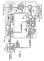
- Figure 1 is a block diagram of one embodiment of an image processor for detecting and tracking targets in accordance with the invention.
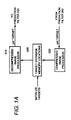
- Figure 1A is a block diagram illustrating a portion of an alternative embodiment of an image processor for tracking and detecting targets in accordance with the invention.
- Figure 2 illustrates one embodiment of a method for producing compressed intensity images in accordance with the invention.
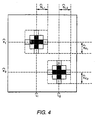
- Figures 3 and 4 illustrate alternative embodiments of a method for producing compressed intensity images in accordance with the invention.
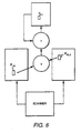
- Figures 5 and 6 illustrate alternative embodiments of a prediction filter for incorporation in an image processor in accordance with the invention.
- a plurality of externally derived data images are available and may be stored in a plurality of memory locations, such as memory locations 400 illustrated in Figure 1.
- each data image corresponds to a particular time t 0 ,t 1 ...t N-1 , where t 0 is typically the reference time for the plurality of data images. Nonetheless, the reference time is not restricted to t 0 and may constitute a time before t 0 , after t N-1 , or between to and t N-1 .
- the images are each comprised of a rectangular array of pixels K rows by L columns having intensity values, each pixel corresponding to a specific location in the rectangular array and having an intensity value I(k,l).
- intensity values may be derived from a received target detection signal amplitude or from other information, such as histogram data.
- each pixel contains the number of target detections which occurred over the pixel "area" in a time interval t i-1 to t i .
- Each data image incorporates target detection signals, such as vibrational energy signals received, for a plurality of targets by a plurality of sensors.
- vibrational energy signals may take a number of forms, such as electromagnetic or sonic signals.
- the images may originate from a number of possible sources, such as conventional sonar or radar systems, although the invention is not limited in this respect.
- One possible source for such a data image incorporating received target detection signals for a plurality of targets may be the output of a phased array sonar system providing correlogram target information in the digital image format previously described.
- target detection signals may be received and then converted to this digital image format.
- a plurality of externally derived reference intensity images are stored in a plurality of memory locations 100.
- Each reference image may incorporate initial target detection signals for at least one target. These images may originate from a number of sources, such as from intelligence information or other information regarding the location and the change in location of the target during a particular time interval or, alternatively, from processing a different set of data images for the same targets using an embodiment of an image processor in accordance with the invention.
- the reference images may be initialized with substantially uniform intensity values indicating no information regarding the location or change in location of the targets and an image processor in accordance with the present invention may be employed to extract updated reference images from the data images provided, as described hereinafter.
- each initially identified target will have two reference images associated with it, an image incorporating information regarding location, such as position, and an image incorporating information regarding change in location, such as velocity.
- image incorporating information regarding location such as position
- image incorporating information regarding change in location such as velocity
- reference images providing information regarding the position and velocity of a plurality of targets are applied to signal processor 200 a pair of images at a time, i.e., on a per target basis.
- signal processor 200 typically may comprise a digital signal processor; alternative embodiments may comprise a microprocessor, an application specific integrated circuit (ASIC), a general purpose digital computer, a massively parallel processor (MPP), or another type of parallel processor.
- signal processor 200 comprises a closed loop feedback system including a simulation filter 210.
- Simulation filter 210 includes a prediction filter 250, which may be a Kalman prediction filter, and a sensor simulation filter 220.
- the closed loop feedback system of signal processor 200 further includes an image generator 255 and a prediction filter 260, as illustrated in Figure 1.
- an image generator 255 and a prediction filter 260, as illustrated in Figure 1.
- a multitude of possible arithmetic/logic circuits may be employed for prediction filters 250 and 260, sensor simulation filter 220, and image generator 255 to enable these image processor elements to perform the image filtering and image forming described hereinafter.
- prediction filter 250 projects or predicts the location of the target in response to the reference images for a given target for the time interval corresponding to the time interval during which the received target detection signals incorporated in the data image would have indicated that the target was sensed or detected. It will be understood that this prediction may be either forward or backward in time relative to the time interval corresponding to the reference images.
- prediction filter 250 predicts the location of a given target for each time interval from t 1 to t N-1 .
- a conventional Kalman prediction filter may be used for prediction filter 250 most effectively where the reference intensity images are stored as compressed intensity images, as described hereinafter.
- a predicted or projected intensity image for a position of a target such as comprised of pixels P r,s , may be constructed by scanning the reference velocity image for that target for each velocity, such as V k,l .
- each pixel V k,l in a velocity intensity image, such as the reference velocity image corresponds to two mutually orthogonal components of velocity respectively represented by the horizontal and vertical displacement of the pixel in the intensity image.
- the predicted position image for that target is constructed by predicting forward or backward in time from every pixel in the reference position image, such as Pm,n, to the predetermined or predicted time and accumulating the image intensities formed by multiplying the corresponding intensity values in the position image and the velocity image for that target. After normalization, this results in a target position image at the predicted time similar to the position image for that target at the reference time.
- prediction filter 250 predicts the location of each target as previously described and these predicted target position images are provided to sensor simulation filter 220.
- Filter 220 first sums or superpositions the predicted images produced by filter 250, such as by summer 230, to form a single target prediction image representing the predicted locations of the targets during the time interval in which the received target detection signals incorporated in the data image would have indicated that the targets were sensed or detected.
- This superposition image or target prediction image is then provided to a sensor filter 240 to produce a simulated intensity image of the data image stored in memory locations 400.
- the simulated image may be stored in a plurality of memory locations 300. Nonetheless, as will appreciated by those skilled in the art, the simulated image may be alternatively provided directly from sensor filter 240 to image generator 255, as shown in Figure 1 by a dashed arrow.
- Sensor filter 240 simulates the effect of the sensor environment by reproducing the effect the presence of a target at a particular location has on the data image. No details regarding the particulars of the filter are provided here since they will depend upon the particular sensor, and effects from multipath, acoustic propagation characteristics, background clutter, etc.
- the sensor filter is implemented as a set of weighting coefficients or weights 235 expressing the effect that the presence of a target in a pixel location has on the pixels in the target position image.
- a particular weighting coefficient of the sensor filter H(k,l;k',l') expresses the effect on the synthesized or simulated pixel value at pixel (k',l'), given the presence of a target at pixel (k,l).
- the simulated image may be produced by a convolution operation of the target prediction image with the sensor filter weights.
- the externally derived sensor filter weights may be periodically updated as the characteristics of the medium change, such as over time.
- the sensor filter may comprise either a simulation or an analytical expression for such sensor environment effects.
- a simulated image for storage in memory locations 300 is then produced and applied to the image generator portion 255 of signal processor 200 executing the image generation.
- the predicted images provided by prediction filter 250, the simulated image stored in memory locations 300 and the data image stored in memory locations 400, are combined by signal processor 200; however, in this embodiment of the invention several steps are executed before such image generation or formation takes place.
- an image comparison is performed by an image comparator 280 to compare the simulated image with the data image to determine whether the simulated image has converged to the data image.
- a number of methods for determining convergence between intensity images are possible.
- the images are compared on a pixel-by-pixel basis.
- the differences in corresponding pixel intensity values may be summed and that sum may be compared to a predetermined amount.
- the differences in corresponding pixel intensity values may be squared and the sum of the squares may be compared to a predetermined amount.
- the magnitude of the difference in corresponding pixel intensity values on a pixel-by-pixel basis may be compared to a predetermined amount.
- the difference in corresponding pixel intensity values on a pixel-by-pixel basis may be squared and compared with a predetermined amount.
- Many other techniques for determining convergence may occur to one skilled in the relevant art and the invention is not limited in scope to the techniques enumerated. If the simulated image has not converged to the data image, additional images are formed by image generator 255.
- An image combiner 270 constructs or forms a plurality of combined images based on the comparison of the simulated image and the data image described above.
- the images may be combined in accordance with a number of other equations chosen to reflect the differences between the data image and the simulated image and provide those differences as a correction to each of the predicted images, such as a function of either D k /S k , given by f(D k /S k ), or D k - S k , given by f(D k /S k ), or a combination thereof.
- a function of either D k /S k given by f(D k /S k ), or D k - S k , given by f(D k /S k ), or a combination thereof.
- prediction filter 260 may comprise a Kalman prediction filter, as previously described regarding prediction filter 250.
- the prediction filter may employ a similar technique as previously described regarding prediction filter 250 for using a target position image and a target velocity image to produce a predicted target position image for the reference time constituting an updated reference image.
- the reference images are then replaced with the updated reference images in memory locations 100.
- the reference velocity images for each target may be updated by filtering the combined target position image and the corresponding reference position image for that target to produce an updated reference velocity image for the target.
- a plurality of combined images for a target may be filtered to produce an updated reference velocity image for that target.
- the prediction filters may be omitted if only one data image is involved.
- signal processor 200 executes a closed loop feedback system for producing a simulated image from the updated reference images until the simulated image converges to the data image.
- this feedback system occurs after convergence between the data image stored in memory locations 400 and the simulated image stored in memory locations 300. If convergence has occurred, then the differences between the data image and the simulated image, e.g., D k - S k in this embodiment, termed the residuals, are filtered. In particular, the residuals should be sufficiently close to uniform with a small enough amplitude, such as on the order of a multiple of the quantization noise, to indicate that all of the targets have been detected. If convergence has occurred, but the residuals are not uniform or have an excessively large amplitude, the presence of a yet unidentified target in the data image is likely.
- the residuals, or their logarithms as previously described are summed and compared with a predetermined amount. If the sum exceeds a predetermined amount, a new or additional target image may be generated by new target image generator 290 in Figure 1.
- a number of possible techniques for filtering the residuals and for forming an additional target image are possible.
- One technique is to filter the residuals for the row and column pixel locations of the mean intensity in the image and for the variance in those row and column pixel locations, and to construct a two-dimensional Gaussian distributed intensity image having substantially the same row and column pixel values for the mean and variance.
- the image may be "thresholded" to identify peaks or spikes in the image before performing the filtering described above.
- the new or additional target image is then provided to prediction filter 260, which performs prediction backward or forward in time to produce a reference image at the reference time corresponding to the newly identified target. In this instance, where a single data image is included in memory locations 400, a substantially uniform target velocity image may prove satisfactory for such prediction.
- Prediction filter 250 predicts the location of the target in a given reference image during the time intervals corresponding to each data image. Thus, filter 250 produces a predicted image for each target for each time interval. These images are provided to filter 220, in which for each time interval, the predicted images corresponding to the targets are superpositioned or summed, as indicated by summer 230, and then convolved with sensor filter 240 to produce a plurality of simulated images in which a simulated image corresponds to each data image.
- Each simulated image is then compared with its corresponding data image to determine whether convergence has occurred. As described previously, determination of convergence will depend on the particular method employed; however, all simulated images should demonstrate convergence to conclude that it has taken place. If convergence has not occurred, a plurality of combined images are constructed, again as previously described. Thus, a combined image is produced for each target for the time intervals corresponding to each data image. All of the combined images corresponding to the time intervals for a given target are then provided to prediction filter 260 which projects backward or forward in time to the reference time to produce a single updated reference position image for that target. This is accomplished by first filtering the combined images to produce an updated reference velocity image for that target.
- the velocity histogram is produced by determining a hypothetical velocity V k,l between every pixel pair P r,s and P m,n in the respective target position images and assigning to that velocity the product of the image intensities for these pixels in the position images.
- V k,l a hypothetical velocity between every pixel pair P r,s and P m,n in the respective target position images
- assigning to that velocity the product of the image intensities for these pixels in the position images assigning to that velocity the product of the image intensities for these pixels in the position images.
- these histograms provide the velocity of the target at the reference time by assuming the target velocity is constant over the relevant time period. This is done between various pairs of target position images with the intensities assigned to corresponding velocities being summed.
- any images having velocity information such as a reference target velocity image, for example, are produced by external target detection systems, such as radar or sonar
- the corresponding intensity values for each velocity may also be summed. After summing the intensities for each velocity, the image is normalized. Then, as previously described, each combined image for the target is projected backwards or forwards to the reference time, and these images are superpositioned and normalized to provide the updated reference position image.
- This process of image filtering, image generating, and reference image updating is repeated until convergence occurs.
- the residuals of each of the simulated images after removing each of the corresponding data images are evaluated, as previously described, to determine whether additional target images should be generated or constructed. If these images are formed, again as previously described, the process of filtering and image generation is repeated until convergence again occurs and until the residuals comprise a substantially uniform distribution or exhibit sufficiently small amplitudes.
- Additional reference images for a newly identified target may be generated by one of a number of approaches in the instance where memory locations 400 include a plurality of data images. Each simulated image corresponding to one of the stored data images may be removed from its corresponding data image to produce a set of residual images, a residual image corresponding to each data image. In one approach, not shown in Figure 1, each of the residual images may be projected by prediction filter 260 either forward or backward to the reference time to correspond with the reference images. At this point, to produce a position image for the newly identified target the residual images may be superpositioned, normalized, and filtered for the row and column pixel locations for the mean intensity and for the variance in these row and column pixel locations, as previously described.
- one of the residual images may be selected, such as the residual image having the least uniform residuals or having the residuals of greatest intensity, and a target position image may be generated from the residuals by new target image generator 290.
- a target velocity image for the newly identified target may be generated by first producing a velocity image for the plurality of targets from the data images stored in memory locations 400, such as by the technique described in conjunction with Figure 6. Then, the residuals remaining after removing each of the reference velocity images from the velocity image produced from the data images may be filtered by any one of the techniques herein described to generate a velocity image for the newly identified target. These position and velocity target images may then be applied to prediction filter 260 to provide additional reference images for the plurality of reference images stored in memory locations 100.
- FIG. 1A An alternative embodiment of an image processor for target detection and tracking in accordance with the present invention is shown in Figure 1A.
- the embodiment illustrated in Figure 1A is substantially identical with the embodiment in Figure 1 except that memory locations 100 coupled to signal processor 200 of Figure 1 are replaced with a target database 500 comprising memory locations for storing compressed target position and target velocity intensity images.
- target database 500 has stored a corresponding compressed intensity image.
- Figure 1A further illustrates a signal processor 510 for decompressing the image before applying it to prediction filter 250 and a signal processor 520 for compressing the image after the image has been produced by prediction filter 260.
- the digital intensity images are filtered for reduced memory storage utilization in accordance with the following method.
- the intensity images to be filtered or compressed are comprised of K x L pixels arranged in K rows and L columns of sampled intensity values, each of these sample intensity values being denoted I(l,k) with l and k corresponding to the row and column location of the sampled intensity value.
- the method comprises the steps of transmitting the sampled intensity values I(k,l) to a signal filtering device, such as a digital signal processor, filtering these sample intensity values with the signal filtering device to produce at least four pixel values providing a compressed digital intensity image, and storing the four filtering-produced pixel values in memory locations.
- the step of filtering the sampled intensity values comprises the steps of filtering the sampled intensity values to produce an estimate of the row pixel location corresponding to the mean of the sampled intensity values and an estimate of the variance of that pixel location, and filtering the sampled intensity values to produce an estimate of the column pixel location corresponding to the mean of the sampled intensity values and an estimate of the variance of that pixel location.
- the step of filtering the sampled intensity values may comprise the steps of filtering the sampled intensity values to produce estimates of the row pixel location with the maximum intensity and the extent in pixels away from that location of intensity values x% of that maximum intensity, where x is between 0 and 100 inclusive, and filtering the sampled intensity values to produce estimates of the column pixel location with the maximum intensity and the extent in pixels away from that location of intensity values y% of that maximum intensity, where y is between 0 and 100 inclusive.
- the mean and estimates, K , L , and variance estimates, S K , S L are calculated in accordance with the following equations:
- the maximum and extent row and column pixel values are determined by first selecting the largest intensity value in the image, designated by pixel values K and,L and, and constructing a "window" around it using one-half of the largest distance between pixels in the image which are a predetermined percentage of the maximum intensity, designated by pixel values This is illustrated in Figure 3.
- the local maxima in the image may be selected and then a window is again constructed around each maxima by "thresholding" the image to those values which are at least a predetermined percentage of the maximum, as illustrated in Figure 4, by a and Finally, the remaining pixels in each of the windows corresponding to the local maxima are used to calculate the mean and variance row and column pixel locations for that window by the method previously applied to a complete intensity image.
- the mean and variance row and column pixel estimates for each window are stored.
- the maximum and extent row and column pixel values are stored. It will be understood that this same filtering method may be applied to target velocity images as well as target position images.
- image reconstruction or decompression takes place by transmitting to an image generator the filtering-produced pixel values that have been stored and producing a digital image with the image generator comprised of K columns and L rows of pixels and having a compressed intensity image corresponding to the filtering-produced pixel values.
- the stored pixel values are mean and variance row and column pixel estimates, this comprises constructing a two-dimensional Gaussian distributed intensity image having the same mean and variance.
- the stored values are maximum and extent pixel values
- a two-dimensional uniform intensity image having the same maximum and extent may be produced.
- image compression and decompression may take place at various locations in signal processor 200 other than those illustrated by Figure 1A.
- any signal processing that takes place on a per target basis, as illustrated in Figure 1 may be compressed and decompressed for improved computational efficiency and reduced memory utilization.
- image compression and decompression as previously described, by its nature must introduce errors into the decompressed or reconstructed image. Nonetheless, in the context of the present invention, the errors introduced have proven not to substantially degrade the performance of the image processor.
- processing one or more data images in accordance with the invention to produce updated reference images may begin with compressed intensity images in place of complete reference intensity images.
- an alternative embodiment of the invention may include filter 220 and image generator 255 without filters 250 and 260.
- Such an embodiment may prove satisfactory where a single data image corresponds to the reference time so that no prediction forward or backward is necessary for satisfactory performance.
- This embodiment operates as previously described except that the reference images are employed for the steps of the previous embodiment involving the predicted images.
- a significant amount of the image processing may be performed in parallel for improved computational efficiency.
- the processing of image pixels in accordance with the invention may be performed by parallel processors, each processor dedicated to particular pixel locations.
Landscapes
- Engineering & Computer Science (AREA)
- Physics & Mathematics (AREA)
- General Physics & Mathematics (AREA)
- Multimedia (AREA)
- Radar, Positioning & Navigation (AREA)
- Electromagnetism (AREA)
- Theoretical Computer Science (AREA)
- Remote Sensing (AREA)
- Radar Systems Or Details Thereof (AREA)
- Measurement Of Velocity Or Position Using Acoustic Or Ultrasonic Waves (AREA)
- Cable Transmission Systems, Equalization Of Radio And Reduction Of Echo (AREA)
- Filters That Use Time-Delay Elements (AREA)
- Image Processing (AREA)
Claims (21)
- Processeur d'image pour produire des images d'intensité mises à jour destinées à être utilisées pour la détection et la poursuite d'une pluralité de cibles, ledit processeur d'image comprenant :des première (100) et seconde (400) pluralités d'emplacements de mémoire pour mémoriser des images d'intensité, etun processeur de signal (200), sensible à une pluralité d'images d'intensité déduites extérieurement, pour produire des images d'intensité mises à jour, ledit processeur de signal (200) étant couplé auxdites première (100) et seconde (400) pluralités d'emplacements de mémoire, lesdites images d'intensité déduites extérieurement comprenant une pluralité d'images de référence, ladite première pluralité d'emplacements de mémoire (100) étant adaptée pour mémoriser lesdites images de référence à l'intérieur de ceux-ci, des paires respectives desdites images de référence comprenant des informations concernant l'emplacement et le changement d'emplacement d'au moins l'une desdites cibles pendant un intervalle de temps prédéterminé, et lesdites images d'intensité déduites extérieurement comprenant au moins une image d'intensité incorporant des signaux de détection de cible reçus fournissant des informations concernant les emplacements desdites cibles pendant un intervalle de temps particulier par rapport audit intervalle de temps prédéterminé, ladite seconde pluralité d'emplacements de mémoire (400) étant adaptée pour mémoriser ladite au moins une image d'intensité à l'intérieur de ceux-ci ;ledit processeur de signal (200) comprenant un système à rétroaction en boucle fermée pour fournir une pluralité d'images pour mettre à jour lesdites images de référence en réponse à ladite au moins une image d'intensité, ledit système comprenant :un premier filtre (210) sensible à ladite pluralité d'images de référence pour produire une image simulée de ladite au moins une image d'intensité ; etun générateur d'images (255) pour former une pluralité d'images combinées pour mettre à jour lesdites images de référence en combinant ladite image simulée avec ladite au moins une image d'intensité.
- Processeur d'image selon la revendication 1, caractérisé par
un second filtre (260) sensible auxdites images combinées pour produire une pluralité d'images pour mettre à jour lesdites images de référence. - Processeur d'image selon la revendication 2,
caractérisé en ce que
ledit processeur de signal (200) comprend un processeur de signal numérique, chacune desdites images étant composée de pixels, chacun desdits pixels ayant une valeur d'intensité. - Processeur d'image selon la revendication 2,
caractérisé en ce queladite première pluralité d'emplacements de mémoire (100) est adaptée pour mémoriser lesdites images de référence en tant qu'images d'intensité compressées ;ledit processeur d'image comprenant, de plus, un processeur de signal pour produire des images de référence à partir des images d'intensité compressées et pour produire des images d'intensité compressées à partir des images de référence. - Processeur d'image selon la revendication 3,
caractérisé en ce que
ledit premier filtre (210) comprend un filtre de prédiction (250) pour produire une pluralité d'images prédites à partir desdites images de référence et un filtre de simulation de capteur (240) pour produire ladite image d'intensité simulée à partir de ladite pluralité d'images prédites. - Processeur d'image selon la revendication 5,
caractérisé en ce que
ledit second filtre (260) comprend un filtre de prédiction pour produire ladite pluralité d'images pour mettre à jour lesdites images de référence à partir desdites images combinées. - Processeur d'image selon la revendication 6,
caractérisé en ce que
chacun desdits filtres de prédiction (250, 260) comprend un filtre de prédiction de Kalman. - Processeur d'image selon la revendication 6,
caractérisé en ce que
ledit générateur d'images (255) est adapté pour former ladite pluralité d'images combinées en combinant séparément chacune desdites images prédites avec ladite au moins une image d'intensité et ladite image d'intensité simulée, de sorte que les différences entre ladite au moins une image d'intensité et ladite image simulée soient incorporées dans ladite pluralité d'images combinées. - Processeur d'image selon la revendication 8,
caractérisé en ce que
ledit générateur d'images (255) est adapté pour former lesdites images combinées conformément à l'équation - Processeur d'image selon la revendication 8,
caractérisé en ce que
ledit processeur de signal numérique comprend un microprocesseur. - Procédé pour produire des images d'intensité destinées à être utilisées pour la détection et la poursuite d'une pluralité de cibles, lesdites images étant formées par un processeur d'image en combinant une pluralité d'images d'intensité déduites extérieurement, au moins l'une desdites images d'intensité déduites extérieurement étant composée de signaux de détection de cible convertis reçus, ladite au moins une image d'intensité constituant une image d'intensité convertie, lesdits signaux de détection fournissant des informations concernant les emplacements desdites cibles pendant un intervalle de temps particulier, les autres desdites images d'intensité déduites extérieurement comprenant une pluralité d'images de référence, des paires respectives desdites images de référence fournissant des informations concernant l'emplacement et le changement d'emplacement d'au moins l'une desdites cibles pendant un intervalle de temps prédéterminé par rapport audit intervalle de temps particulier, ledit procédé comprenant les étapes consistant à :produire une image d'intensité simulée de ladite au moins une image d'intensité convertie déduite extérieurement à partir desdites images 'de référence en filtrant lesdites images de référence ; etformer une pluralité d'images d'intensité combinées en combinant ladite image d'intensité simulée avec ladite image d'intensité convertie.
- Procédé selon la revendication 11,
caractérisé en ce qu'il comprend, de plus, avant l'étape consistant à produire, les étapes consistant à :recevoir des signaux de détection de cible pour ladite pluralité de cibles ; etconvertir lesdits signaux de détection de cible reçus en ladite au moins une image d'intensité. - Procédé selon la revendication 11,
caractérisé en ce qu'il comprend, de plus, à la suite de l'étape consistant à former, les étapes consistant à :produire une pluralité d'images de référence mises à jour à partir desdites images d'intensité combinées en filtrant lesdites images d'intensité combinées ; etexécuter de manière récursive les étapes énumérées précédemment de production d'une image d'intensité simulée, de formation d'une pluralité d'images d'intensité combinées et de production d'une pluralité d'images de référence mises à jour jusqu'à ce que les différences entre la dernière image d'intensité simulée produite et ladite image d'intensité convertie convergent vers un niveau prédéterminé. - Procédé selon la revendication 13,
caractérisé en ce qu'il comprend, de plus, les étapes supplémentaires consistant à :produire une image d'intensité résiduelle correspondant aux différences entre ladite dernière image simulée produite et ladite image convertie après la convergence vers un niveau prédéterminé ;former deux images de référence à partir de ladite image d'intensité résiduelle fournissant des informations concernant l'emplacement et le changement d'emplacement d'une autre cible ; etexécuter de manière récursive les étapes consistant à produire une autre image d'intensité simulée, à former une pluralité d'images d'intensité combinées et à produire une pluralité d'images de référence mises à jour jusqu'à ce que les différences entre la dernière autre image d'intensité simulée produite et ladite image d'intensité convertie convergent vers un niveau prédéterminé. - Procédé selon la revendication 13,
caractérisé en ce qu'il comprend, de plus, l'étape consistant à mémoriser lesdites images de référence dans ladite première pluralité d'emplacements de mémoire en tant qu'images d'intensité compressées ; etdans lequel l'étape consistant à produire une image d'intensité simulée comprend, de plus, l'étape consistant à former des images de référence à partir desdites images d'intensité compressées ; etdans lequel l'étape consistant à produire une pluralité d'images de référence mises à jour à partir desdites images combinées comprend, de plus, l'étape consistant à former des images de référence mises à jour compressées à partir desdites images de référence mises à jour. - Procédé selon la revendication 13,
caractérisé en ce queau moins une autre desdites images déduites extérieurement est composée de signaux de détection de cible convertis reçus, ladite au moins une autre image déduite extérieurement constituant une autre image d'intensité convertie, les signaux de détection de cible convertis cités en dernier fournissant des informations concernant les emplacements desdites cibles pendant un autre intervalle de temps ;dans lequel l'étape consistant à produire une image d'intensité simulée comprend la production d'une image d'intensité simulée de ladite autre image d'intensité convertie ;dans lequel l'étape consistant à former comprend la formation d'une pluralité d'images d'intensité combinées en combinant chacune desdites images d'intensité simulées avec l'image d'intensité convertie correspondante ; etdans lequel l'étape consistant à exécuter de manière récursive les étapes énumérées précédemment est exécutée jusqu'à ce que les différences entre chacune desdites dernières images d'intensité simulées produites et l'image d'intensité convertie correspondante convergent vers une quantité prédéterminée. - Procédé selon la revendication 13,
caractérisé en ce que
l'étape consistant à produire une image simulée comprend les étapes consistant à :produire une pluralité d'images prédisant les emplacements desdites cibles pendant ledit intervalle de temps particulier en appliquant lesdites images de référence à un filtre de prédiction ;former une image de prédiction de cible en superposant ladite pluralité d'images prédites ; etappliquer ladite image de prédiction de cible à un filtre de simulation de capteur afin de produire ladite image simulée. - Procédé selon la revendication 17,
caractérisé en ce que
l'étape consistant à former lesdites images d'intensité combinées comprend l'étape consistant à produire une pluralité d'images combinées d'une manière selon laquelle chacune desdites images prédites est combinée séparément avec ladite image d'intensité convertie et ladite image simulée, de sorte que les différences entre ladite image d'intensité convertie et ladite image simulée soient incorporées dans lesdites images d'intensité combinées. - Procédé selon la revendication 18,
caractérisé en ce que
lesdites images d'intensité combinées, prédites, converties et simulées sont composées d'un certain nombre correspondant de pixels arrangés selon un agencement rectangulaire, l'étape consistant à former ladite pluralité d'images d'intensité combinées étant conforme à l'équation - Procédé selon la revendication 19,
caractérisé en ce que
l'étape consistant à produire lesdites images d'intensité de référence mises à jour comprend l'étape consistant à appliquer lesdites images d'intensité combinées à un filtre de prédiction. - Procédé selon la revendication 20,
caractérisé en ce que
lesdits signaux de détection de cible comprennent des signaux d'énergie vibratoire, des signaux sonores ou électromagnétiques.
Applications Claiming Priority (2)
| Application Number | Priority Date | Filing Date | Title |
|---|---|---|---|
| US953912 | 1992-09-30 | ||
| US07/953,912 US5390133A (en) | 1992-09-30 | 1992-09-30 | Image processor for target detection and tracking |
Publications (3)
| Publication Number | Publication Date |
|---|---|
| EP0590846A2 EP0590846A2 (fr) | 1994-04-06 |
| EP0590846A3 EP0590846A3 (fr) | 1994-11-30 |
| EP0590846B1 true EP0590846B1 (fr) | 2002-01-02 |
Family
ID=25494716
Family Applications (1)
| Application Number | Title | Priority Date | Filing Date |
|---|---|---|---|
| EP93307464A Expired - Lifetime EP0590846B1 (fr) | 1992-09-30 | 1993-09-21 | Processeur d'images pour détection et poursuite de cibles |
Country Status (5)
| Country | Link |
|---|---|
| US (1) | US5390133A (fr) |
| EP (1) | EP0590846B1 (fr) |
| JP (1) | JPH06201826A (fr) |
| AU (1) | AU667395B2 (fr) |
| DE (1) | DE69331407T2 (fr) |
Families Citing this family (35)
| Publication number | Priority date | Publication date | Assignee | Title |
|---|---|---|---|---|
| CA2107068C (fr) * | 1993-09-27 | 2003-04-15 | Brian M. Barry | Repartiteur de donnees parametrique adaptatif pour la saisie et la poursuite de signaux discrets entrelaces |
| US5798942A (en) * | 1994-04-05 | 1998-08-25 | Trw Inc. | N-best feasible hypotheses multitarget tracking system for space-based early warning systems |
| DE4439742C1 (de) * | 1994-10-28 | 1996-03-07 | Daimler Benz Ag | Verfahren zur automatischen kombinatorischen Optimierung von Zuordnungen bei der Bahnverfolgung mehrerer sich bewegender Objekte |
| FR2734911B1 (fr) * | 1995-06-01 | 1997-08-01 | Aerospatiale | Procede et dispositif pour detecter le mouvement d'une cible et leurs applications |
| US5947413A (en) * | 1996-11-12 | 1999-09-07 | Raytheon Company | Correlation filters for target reacquisition in trackers |
| SE510436C2 (sv) * | 1997-06-19 | 1999-05-25 | Celsiustech Sustems Ab | Måltypsestimering vid målspårning |
| US6535833B1 (en) * | 1999-11-22 | 2003-03-18 | Nokia Mobile Phones Ltd. | Method and apparatus for filtering measurements used in a generalized positioning system |
| US7408572B2 (en) * | 2002-07-06 | 2008-08-05 | Nova Research, Inc. | Method and apparatus for an on-chip variable acuity imager array incorporating roll, pitch and yaw angle rates measurement |
| US7298867B2 (en) * | 2004-02-20 | 2007-11-20 | Lockheed Martin Corporation | Component association tracker system and method |
| JP2008503810A (ja) * | 2004-06-22 | 2008-02-07 | ラビット・ジョイント・ベンチャー・リミテッド | 信号処理方法及び装置 |
| US7477785B2 (en) | 2004-11-19 | 2009-01-13 | Microsoft Corporation | Fuzzy image comparator |
| US7620248B2 (en) * | 2004-11-19 | 2009-11-17 | Microsoft Corporation | System and method for validating graphical components of images |
| US20060110043A1 (en) * | 2004-11-19 | 2006-05-25 | Microsoft Corporation | System and method for validating graphical components of images by analysis |
| US20060110045A1 (en) * | 2004-11-19 | 2006-05-25 | Microsoft Corporation | System and method for validating graphical components of images |
| US7639841B2 (en) * | 2004-12-20 | 2009-12-29 | Siemens Corporation | System and method for on-road detection of a vehicle using knowledge fusion |
| PL1913557T3 (pl) * | 2005-06-23 | 2016-12-30 | System i metoda śledzenia poruszających się obiektów | |
| US8370113B2 (en) * | 2006-09-29 | 2013-02-05 | Netlogic Microsystems, Inc. | Low-power and low-cost adaptive self-linearization system with fast convergence |
| US8054217B2 (en) | 2006-10-26 | 2011-11-08 | Raytheon Company | Radar imaging system and method using gradient magnitude second moment spatial variance detection |
| US8212717B2 (en) * | 2006-10-26 | 2012-07-03 | Raytheon Company | Radar imaging system and method using second moment spatial variance |
| FR2923024B1 (fr) * | 2007-10-26 | 2010-08-13 | Thales Sa | Procede de detection d'une cible |
| ES2407830T3 (es) * | 2008-08-28 | 2013-06-14 | Saab Ab | Un sistema de seguimiento de objetivos y un procedimiento para el seguimiento de un objetivo |
| US20110148928A1 (en) * | 2009-12-17 | 2011-06-23 | General Electric Company | System and method to correct motion in gated-pet images using non-rigid registration |
| IL219639A (en) | 2012-05-08 | 2016-04-21 | Israel Aerospace Ind Ltd | Remote object tracking |
| WO2014111923A1 (fr) | 2013-01-15 | 2014-07-24 | Israel Aerospace Industries Ltd | Suivi à distance d'objets |
| IL224273B (en) | 2013-01-17 | 2018-05-31 | Cohen Yossi | Delay compensation during remote sensor control |
| US9939525B2 (en) * | 2013-11-29 | 2018-04-10 | L.H. Kosowsky & Associates, Inc. | Imaging system for obscured environments |
| US10309784B2 (en) | 2014-07-31 | 2019-06-04 | Honeywell International Inc. | Merging intensities in a PHD filter based on a sensor track ID |
| US10605607B2 (en) | 2014-07-31 | 2020-03-31 | Honeywell International Inc. | Two step pruning in a PHD filter |
| US9851437B2 (en) * | 2014-07-31 | 2017-12-26 | Honeywell International Inc. | Adjusting weight of intensity in a PHD filter based on sensor track ID |
| US11175142B2 (en) | 2014-07-31 | 2021-11-16 | Honeywell International Inc. | Updating intensities in a PHD filter based on a sensor track ID |
| US10234553B2 (en) * | 2014-09-19 | 2019-03-19 | GM Global Technology Operations LLC | Doppler-based compression of imaging radar data |
| US10349087B2 (en) * | 2017-07-13 | 2019-07-09 | The University Of North Carolina At Chapel Hill | Methods, systems, and computer readable media for reconstructing images using blurring and noise-enhanced pixel intensity resampling |
| TWI762243B (zh) * | 2021-03-17 | 2022-04-21 | 緯創資通股份有限公司 | 頻率調變連續波雷達、數位訊號處理方法與表徵資訊偵測方法 |
| CN117852925B (zh) * | 2024-01-16 | 2024-08-20 | 国信蓝桥教育科技股份有限公司 | 一种基于虚拟仿真的物联网实训分数评估方法及系统 |
| CN119270218B (zh) * | 2024-11-12 | 2025-10-17 | 中国人民解放军国防科技大学 | 一种雷达微弱目标混合积累检测性能分析方法及装置 |
Family Cites Families (14)
| Publication number | Priority date | Publication date | Assignee | Title |
|---|---|---|---|---|
| US4405940A (en) * | 1977-05-31 | 1983-09-20 | Westinghouse Electric Corp. | Apparatus and method for preprocessing video frame signals |
| US4490851A (en) * | 1982-04-16 | 1984-12-25 | The United States Of America As Represented By The Secretary Of The Army | Two-dimensional image data reducer and classifier |
| DE3241896A1 (de) * | 1982-11-12 | 1984-05-17 | Licentia Patent-Verwaltungs-Gmbh, 6000 Frankfurt | Verfahren zur verbesserung der bildverarbeitung bei optronischen flugkoerpererfassungsgeraeten |
| US4719584A (en) * | 1985-04-01 | 1988-01-12 | Hughes Aircraft Company | Dual mode video tracker |
| US4855932A (en) * | 1987-07-08 | 1989-08-08 | Lockheed Electronics Company | Three-dimensional electro-optical tracker |
| US4937878A (en) * | 1988-08-08 | 1990-06-26 | Hughes Aircraft Company | Signal processing for autonomous acquisition of objects in cluttered background |
| FR2656106B1 (fr) * | 1988-12-12 | 1992-06-05 | Thomson Csf | Procede et dispositif d'acquisition automatique de cibles. |
| US5005147A (en) * | 1988-12-30 | 1991-04-02 | The United States Of America As Represented By The Administrator, The National Aeronautics And Space Administration | Method and apparatus for sensor fusion |
| US5062056A (en) * | 1989-10-18 | 1991-10-29 | Hughes Aircraft Company | Apparatus and method for tracking a target |
| JPH04157889A (ja) * | 1990-10-20 | 1992-05-29 | Fujitsu Ltd | 人物撮像位置の自動調整方法 |
| US5150426A (en) * | 1990-11-20 | 1992-09-22 | Hughes Aircraft Company | Moving target detection method using two-frame subtraction and a two quadrant multiplier |
| GB9025797D0 (en) * | 1990-11-28 | 1991-01-09 | Hitachi Europ Ltd | Motion target tracking system |
| US5214433A (en) * | 1992-06-17 | 1993-05-25 | The United States Of America As Represented By The Secretary Of The Navy | Two-stage target tracking system and method |
| GB2270436A (en) * | 1992-09-05 | 1994-03-09 | Ibm | Target tracking system |
-
1992
- 1992-09-30 US US07/953,912 patent/US5390133A/en not_active Expired - Lifetime
-
1993
- 1993-09-16 AU AU47403/93A patent/AU667395B2/en not_active Ceased
- 1993-09-21 DE DE69331407T patent/DE69331407T2/de not_active Expired - Fee Related
- 1993-09-21 EP EP93307464A patent/EP0590846B1/fr not_active Expired - Lifetime
- 1993-09-27 JP JP5238649A patent/JPH06201826A/ja active Pending
Also Published As
| Publication number | Publication date |
|---|---|
| JPH06201826A (ja) | 1994-07-22 |
| EP0590846A3 (fr) | 1994-11-30 |
| EP0590846A2 (fr) | 1994-04-06 |
| AU667395B2 (en) | 1996-03-21 |
| DE69331407T2 (de) | 2002-09-19 |
| US5390133A (en) | 1995-02-14 |
| AU4740393A (en) | 1994-04-14 |
| DE69331407D1 (de) | 2002-02-07 |
Similar Documents
| Publication | Publication Date | Title |
|---|---|---|
| US5390133A (en) | Image processor for target detection and tracking | |
| US12352849B2 (en) | Methods and systems for detection of objects in a vicinity of a vehicle | |
| US5500904A (en) | System and method for indicating a change between images | |
| US5146228A (en) | Coherent correlation addition for increasing match information in scene matching navigation systems | |
| Thrun et al. | Monte carlo localization with mixture proposal distribution | |
| Arnold et al. | Efficient target tracking using dynamic programming | |
| Reed et al. | A recursive moving-target-indication algorithm for optical image sequences | |
| Davey et al. | Using phase to improve track-before-detect | |
| US5170440A (en) | Perceptual grouping by multiple hypothesis probabilistic data association | |
| EP0399180B1 (fr) | Méthode et appareil de surveillance et poursuite de cibles | |
| CN114720969A (zh) | 用于压缩雷达数据的方法和系统 | |
| CN118642106B (zh) | 一种基于气象数据的深度学习sar海杂波仿真与抑制方法 | |
| Tripathi et al. | Innovation-based fractional order adaptive Kalman filter | |
| CN121477177A (zh) | 基于nomp的高特征分辨率水下弱目标参数估计方法 | |
| Pulford | A survey of manoeuvring target tracking methods | |
| EP0802425A2 (fr) | Synthèse d'image à ouverture totale au moyen de mesures d'images à ouverture tournante en forme de bandes | |
| Clark et al. | PHD filter multi-target tracking in 3D sonar | |
| CN119395686B (zh) | 一种非线性场景多目标跟踪方法、系统及存储介质 | |
| US5737249A (en) | Active sonar range-beam partitioner | |
| US11202040B2 (en) | System and method for monitoring a sample | |
| Teimouri et al. | A hybrid localization method for a soccer playing robot | |
| Bruno et al. | The optimal 2D multiframe detector/tracker | |
| CN121432337B (zh) | 一种基于轨迹泊松多伯努利混合滤波的相干匹配场跟踪方法及其系统 | |
| Gaetjens et al. | A tale of three priors | |
| CN120802204B (zh) | 一种基于人工智能的雷达信号处理方法及装置 |
Legal Events
| Date | Code | Title | Description |
|---|---|---|---|
| PUAI | Public reference made under article 153(3) epc to a published international application that has entered the european phase |
Free format text: ORIGINAL CODE: 0009012 |
|
| AK | Designated contracting states |
Kind code of ref document: A2 Designated state(s): DE FR GB IT |
|
| PUAL | Search report despatched |
Free format text: ORIGINAL CODE: 0009013 |
|
| AK | Designated contracting states |
Kind code of ref document: A3 Designated state(s): DE FR GB IT |
|
| 17P | Request for examination filed |
Effective date: 19950530 |
|
| 17Q | First examination report despatched |
Effective date: 19991222 |
|
| GRAG | Despatch of communication of intention to grant |
Free format text: ORIGINAL CODE: EPIDOS AGRA |
|
| GRAG | Despatch of communication of intention to grant |
Free format text: ORIGINAL CODE: EPIDOS AGRA |
|
| GRAH | Despatch of communication of intention to grant a patent |
Free format text: ORIGINAL CODE: EPIDOS IGRA |
|
| GRAH | Despatch of communication of intention to grant a patent |
Free format text: ORIGINAL CODE: EPIDOS IGRA |
|
| RAP1 | Party data changed (applicant data changed or rights of an application transferred) |
Owner name: LOCKHEED MARTIN CORPORATION |
|
| GRAA | (expected) grant |
Free format text: ORIGINAL CODE: 0009210 |
|
| REG | Reference to a national code |
Ref country code: GB Ref legal event code: IF02 |
|
| AK | Designated contracting states |
Kind code of ref document: B1 Designated state(s): DE FR GB IT |
|
| PG25 | Lapsed in a contracting state [announced via postgrant information from national office to epo] |
Ref country code: IT Free format text: LAPSE BECAUSE OF FAILURE TO SUBMIT A TRANSLATION OF THE DESCRIPTION OR TO PAY THE FEE WITHIN THE PRESCRIBED TIME-LIMIT;WARNING: LAPSES OF ITALIAN PATENTS WITH EFFECTIVE DATE BEFORE 2007 MAY HAVE OCCURRED AT ANY TIME BEFORE 2007. THE CORRECT EFFECTIVE DATE MAY BE DIFFERENT FROM THE ONE RECORDED. Effective date: 20020102 |
|
| REF | Corresponds to: |
Ref document number: 69331407 Country of ref document: DE Date of ref document: 20020207 |
|
| ET | Fr: translation filed | ||
| REG | Reference to a national code |
Ref country code: FR Ref legal event code: TP |
|
| PG25 | Lapsed in a contracting state [announced via postgrant information from national office to epo] |
Ref country code: GB Free format text: LAPSE BECAUSE OF NON-PAYMENT OF DUE FEES Effective date: 20020921 |
|
| PLBE | No opposition filed within time limit |
Free format text: ORIGINAL CODE: 0009261 |
|
| STAA | Information on the status of an ep patent application or granted ep patent |
Free format text: STATUS: NO OPPOSITION FILED WITHIN TIME LIMIT |
|
| 26N | No opposition filed | ||
| PG25 | Lapsed in a contracting state [announced via postgrant information from national office to epo] |
Ref country code: DE Free format text: LAPSE BECAUSE OF NON-PAYMENT OF DUE FEES Effective date: 20030401 |
|
| GBPC | Gb: european patent ceased through non-payment of renewal fee |
Effective date: 20020921 |
|
| PG25 | Lapsed in a contracting state [announced via postgrant information from national office to epo] |
Ref country code: FR Free format text: LAPSE BECAUSE OF NON-PAYMENT OF DUE FEES Effective date: 20030603 |
|
| REG | Reference to a national code |
Ref country code: FR Ref legal event code: ST |