EP0590852A2 - Séparation de couleurs pour impression graphique en couleurs avec mémoire limitée - Google Patents
Séparation de couleurs pour impression graphique en couleurs avec mémoire limitée Download PDFInfo
- Publication number
- EP0590852A2 EP0590852A2 EP93307475A EP93307475A EP0590852A2 EP 0590852 A2 EP0590852 A2 EP 0590852A2 EP 93307475 A EP93307475 A EP 93307475A EP 93307475 A EP93307475 A EP 93307475A EP 0590852 A2 EP0590852 A2 EP 0590852A2
- Authority
- EP
- European Patent Office
- Prior art keywords
- color
- black
- band
- data
- block
- Prior art date
- Legal status (The legal status is an assumption and is not a legal conclusion. Google has not performed a legal analysis and makes no representation as to the accuracy of the status listed.)
- Granted
Links
Images


Classifications
-
- G—PHYSICS
- G06—COMPUTING OR CALCULATING; COUNTING
- G06K—GRAPHICAL DATA READING; PRESENTATION OF DATA; RECORD CARRIERS; HANDLING RECORD CARRIERS
- G06K15/00—Arrangements for producing a permanent visual presentation of the output data, e.g. computer output printers
- G06K15/02—Arrangements for producing a permanent visual presentation of the output data, e.g. computer output printers using printers
- G06K15/10—Arrangements for producing a permanent visual presentation of the output data, e.g. computer output printers using printers by matrix printers
- G06K15/102—Arrangements for producing a permanent visual presentation of the output data, e.g. computer output printers using printers by matrix printers using ink jet print heads
-
- H—ELECTRICITY
- H04—ELECTRIC COMMUNICATION TECHNIQUE
- H04N—PICTORIAL COMMUNICATION, e.g. TELEVISION
- H04N1/00—Scanning, transmission or reproduction of documents or the like, e.g. facsimile transmission; Details thereof
- H04N1/46—Colour picture communication systems
- H04N1/52—Circuits or arrangements for halftone screening
-
- G—PHYSICS
- G06—COMPUTING OR CALCULATING; COUNTING
- G06K—GRAPHICAL DATA READING; PRESENTATION OF DATA; RECORD CARRIERS; HANDLING RECORD CARRIERS
- G06K2215/00—Arrangements for producing a permanent visual presentation of the output data
- G06K2215/0002—Handling the output data
- G06K2215/0062—Handling the output data combining generic and host data, e.g. filling a raster
- G06K2215/0071—Post-treatment of the composed image, e.g. compression, rotation
-
- G—PHYSICS
- G06—COMPUTING OR CALCULATING; COUNTING
- G06K—GRAPHICAL DATA READING; PRESENTATION OF DATA; RECORD CARRIERS; HANDLING RECORD CARRIERS
- G06K2215/00—Arrangements for producing a permanent visual presentation of the output data
- G06K2215/0082—Architecture adapted for a particular function
- G06K2215/0094—Colour printing
Definitions
- This invention relates to the field of liquid ink printing systems, for example ink jet printing systems, and, more particularly, to methods for improving resolution and print quality in four-color ink jet printing systems.
- CMY Cyan, Magenta and Yellow
- Process black composite black
- Some ink jet printers employ both a color pen and a black pen, but not for use at the same time. In other words, only one or the other pen may be used in the printer at one time.
- Commercial examples are the Hewlett-Packard DeskWriter CTM and DeskJet 500 CTM. Because only one pen can be used at a time, a page is either color or black, but not a mix of color and black on the same page. The user must manually swap pens before a page prints if the wrong pen is in the printer. When the color pen is in use, areas that should be black are printed using composite black. This compromises print quality and printing speed, for the reasons stated above.
- CMYK primary colors plus black
- CMYK complementary metal-oxide-semiconductor
- CMYK complementary metal-oxide-semiconductor
- the Hewlett-Packard PaintJet XLTM contains four print heads, one each for CMY and K. While that printer does not have to use composite black, its resolution is only 180 dots per inch (DPI).
- the Kodak DACONIX Color 4 Printer also contains four print heads for CMYK, only at 192 DPI.
- the Sharp JX-730 Color Ink Jet Printer is another four color printer that is 216 DPI. Both the Kodak and Sharp printers can print black adjacent to color, but again, at much lower resolution and only on special paper.
- delta a minimum spacing
- the processing problem is further complicated when the entire image is not available for evaluation at one time, such as when the image is generated in a piece-meal fashion.
- Generating the image piece-meal is commonly done in computers with a limited amount of memory to generate the image.
- banding the computer needs only enough memory to manipulate one portion of image being generated, each of the portions being known as a band.
- the computer After the computer has imaged a single band, it sends the band to the printer before beginning to form the next band of the image. In this way, the entire image can be generated in an amount of memory substantially less than required to generate the entire image at once, approximately 1/N the amount of memory, where N is equal to the number of bands used.
- the banding process is able to dynamically adjust the size of the bands to match the amount of memory available in the computer.
- the complication for the color separation process arises at the boundaries between adjacent bands. Because only a single band is imaged at a time, the banding process does not know the color properties of the pixels in an adjacent band. For example, if, in the current band, a vertical black line terminates on a band boundary, there is no information within the current band to determine whether there is color in the adjacent band within the minimum spacing of the black line. As a result, it cannot be determined whether to print the line in true black or composite black without some knowledge of future bands.
- An object of the present invention is to allow mixing color and true black printing within a single printed page at high resolution.
- Another object is to increase resolution in four-color liquid ink printing on plain non-glossy paper.
- Another object is to maintain a predetermined minimum spacing between true black ink and color ink across band boundaries in printing systems that employ banding.
- a further object is to compensate for pen misalignment in a two-pen four-color printing system.
- Another object is to speed processing of bit-map color plane data to improve printing speed in a color printing system.
- Another object is to design and implement a very high speed strategy for modifying bit-map color plane data so as to maximize use of true black ink while maintaining a minimum spacing between black ink and color ink, all without unduly slowing the printing process.
- the new method initially separates data that represents black from data that represents color.
- Data that represents black is moved into a "K plane" from the CMY planes.
- the CMY planes control their respective colors in the color pen, and the K plane controls the K pen.
- the present method calls for first identifying color graphics data in the color (CMY) planes that represents composite black (i.e. the corresponding bits are turned on in all three CMY planes), and replacing that data with data in the K plane. This is done in a manner that maintains a predetermined minimum spacing - delta - between K plane bits and color plane bits. Initially, composite black data is moved from the CMY planes to the K plane, thus changing it from representing composite black to representing (true) black. But this cannot be done blindly, as the new K plane data in some cases would violate the minimum spacing restriction. In such cases, composite black must be used. So the method next detects and corrects minimum spacing violations.
- the next step is to re-check the data to detect new spacing violations resulting from the corrections, etc.
- This re-checking may be implemented recursively, though it need not necessarily be done in that manner. Additional details for carrying out these methods at high speed, to maximize printing throughput, are disclosed.
- CMY planes which are approximately 1 Megabyte each
- black tables which are 16 Kilobytes each
- the method proceeds with examining the true black data and the color data, to detect data representing black dots within a predetermined minimum spacing from color dots. If such data is detected, it is corrected by re-designating the offending black data as composite black data for printing in color ink. This new color data may be too close to black data, however. So the method further calls for repeating the examining and re-designating steps until no black dots are detected within the minimum spacing from color dots. Similarly, question mark data is converted to color data since anything within a predetermined minimum spacing of color must be printed with color.
- a similar sequence of steps are applied to the question mark data. If black data is within the minimum spacing from question mark data, the black data is redesignated as question mark data. If after the question mark data has been examined there are no such data, the processing of the band is complete and the band can be sent to the printer for printing. Printing the data includes printing the true black data using black ink, and printing the color data, including the composite black bits, using color ink, thereby maintaining at least the minimum spacing between black dots and color dots on the printed page.
- the indeterminate band is temporarily stored, i.e., spooled, to a secondary storage device (such as a disk drive) awaiting additional information.
- a secondary storage device such as a disk drive
- the question mark bits Prior to storing the band, the question mark bits are converted to black bits, since there is a high probability that the question mark bits will ultimately turn out to be black. If, however, that assumption turns out to be false, and any of the question mark bits resolve to color bits, the spooled band must be abandoned and the band reimaged.
- any additional processing normally done on the band e.g., compression, color matching, ink depletion, or edge enhancement, is completed.
- the secondary storage is examined for any pending spooled bands, which may have been resolved based on the processing of the current band. If there are any pending bands and there are remaining question marks, no more pending bands are examined since additional information is still required and therefore the next band is requested. If new color has propagated up into one of the pending bands, i.e., we assumed incorrectly that the question marks would be resolved to black, the pending band must be discarded and the band reimaged. If, however, the assumption is correct and the question marks were resolved as black, the pending band is forwarded on to the printer for printing in the manner described above. This process is repeated until all of the pending bands have been examined.
- the step of examining the data is done expeditiously by first selecting a block size equal to at least the minimum spacing in both vertical and horizontal dimensions. Next is partitioning the input data to define a series of blocks of the selected block size. Each one of the series of blocks is designated as color, black or white. Having done so, we examine the block designations to detect black blocks adjacent color blocks. Where this occurs, the detected black blocks are re-designated as color blocks. These steps are repeated until no black blocks are detected adjacent color blocks, thereby ensuring at least the minimum spacing between color data and black data. Thereafter, printing the black blocks using black ink and printing the color blocks using color inks completes the printing process.
- the processed data can of course be stored to a file or otherwise transferred, for example, for deferred or remote printing operations.
- each block has a series of bits, each black table bit corresponding to a respective one of the K plane blocks, and indicating by its binary state whether or not the corresponding K plane block is a black block.
- the color table has a series of bits, each color table bit corresponding to a respective one of the color plane blocks and indicating whether or not the corresponding color plane block is a color block.
- the corresponding bits in both the color and black tables are used since the two tables are mutually exclusive otherwise.
- the method calls for examining adjacent bits in the black table as follows. First, testing a corresponding black table byte to detect an indication of a black block to the left or right of the color table bit, thereby indirectly detecting a black block adjacent the color block. The method further includes testing black table bytes directly above and below the corresponding black table byte detect any adjacent on bits indicating adjacent black blocks. Diagonally adjacent locations in the black table are tested as well. The process is similarly applied to question mark blocks adjacent to color blocks, with the resulting question mark blocks being converted to color blocks. Similarly, black blocks adjacent to question mark blocks can be easily ascertained.
- the invention thus includes methods of processing graphics input data for output at high resolution with adequate color separation.
- the resulting output data may be used to drive a CRT or other color display device, or to control a liquid-ink printer as is illustrated in the preferred embodiment.
- the new methodology is useful in any output or rendering application in which separation of one "color” or ink (black in the example) from other colors by at least a minimum spacing is desired.
- FIG. 1 is an illustration of an array of ink dot locations on a substrate showing a six-dot spacing around a selected dot location.
- FIGS. 2-4 illustrate examples of valid configurations of ink drops applied to a substrate in which a predetermined minimum distance (six dots) is maintained between each black dot and each color or composite black dot.
- FIGS. 5-6 illustrate examples of invalid configurations of ink dots applied to a substrate in that, in each example, at least one color or composite black dot is located less than the minimum spacing from a black dot.
- FIG. 7A illustrates a portion of a combined color (CMY) plane which is partitioned to form three rows by eight columns of blocks, each block consisting of eight bytes of data.
- CY combined color
- FIG. 7B illustrates a portion of a color table in which each bit corresponds to a respective one of the data blocks of FIG. 8A and indicates whether or not the corresponding block has any color bits ON.
- FIG. 8A illustrates a K (black) plane which is partitioned to form three rows by eight columns of blocks in the same manner as the color plane of FIG. 8A.
- FIG. 8B illustrates a portion of a black table in which each bit corresponds to a respective one of the data blocks of FIG. 9A and indicates whether or not the corresponding block has any K bits ON.
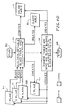
- FIG. 9 is a top-level flowchart of the steps taken for each of the bands received of a banded image.
- FIG. 10 is a conceptual diagram illustrating a method according to the present invention of processing CMY color data for printing by a 4-color (CMYK) liquid ink printing system so as to maximize use of black ink while maintaining a predetermined minimum spacing between black blocks and color blocks.
- CMYK 4-color
- FIG. 11 is a flowchart of a process for determining whether a given block of data is color, white or black, ie. whether a given block should be printed by the color pen or the black pen.
- FIG. 12 illustrates a portion of a color table in which one bit is ON, and identifies the pertinent surrounding bits in the corresponding black table.
- FIG. 13A is a portion of a color table with two bits ON.
- FIG. 13B is the color table of FIG. 13A with same-row neighbor bits turned ON (a "mask").
- FIG. 13C is a portion of a black table corresponding to FIGS. 13A and 13B.
- FIG. 13D shows the resulting mask after logically ANDing the black table of FIG. 13C with the mask of FIG. 13B.
- FIG. 14A shows a portion of a color table in which the leftmost bit of one byte is ON.
- FIG. 14B is a portion of a black table corresponding to the color table of FIG. 14A and indicating by 1's three bits adjacent the ON bit of FIG. 14A.
- FIG. 14C is a portion of a color table in which the rightmost bit of a selected byte is ON.
- FIG. 14D is a portion of a black table corresponding to the color table of FIG. 14C and indicating by 1's the bits adjacent the ON bit of FIG. 14C.
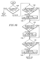
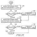
- FIGS. 15-17 show a flowchart of a method of examining the color table and black table to detect black blocks which are adjacent to color blocks.
- FIG. 18 is a flowchart of a method of moving selected data from the black plane into the color planes in order to correct minimum spacing violations.
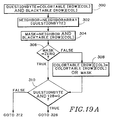
- FIGS. 19A-19D show a flowchart of a method of examining the black and color tables to detect black blocks which are adjacent to question mark blocks.
- FIG. 20 shows a flowchart of a method of examining each of the spooled bands to determine the action required for each.
- FIG. 21 shows a flowchart of a method of determining the action required for the current band.
- FIG. 22 shows a flowchart of a method of removing the question mark blocks from the color table.
- FIGS. 23-25 illustrate operation of the invention as applied to a specific example of a graphics image.
- FIG. 26 shows a banded image with the band boundaries shown as horizontal lines across the page.
- CMY The colors Cyan, Magenta and Yellow are referred to as CMY .
- Black is referred to as K (K instead of B, so as to not confuse this color with Blue).
- two pens are provided - one containing the color inks CMY and the other containing black ink. These are called the color pen and the black pen, respectively.
- Black printed on the page using the color pen i.e. a combination of CMY
- black printed on the page using the black pen will simply be called black.
- a dot (also called a pixel) is the smallest single area on the page that a pen can place ink.
- a commercial embodiment of the invention provides for printing at a resolution of 300 Dots Per Inch (DPI) both vertically and horizontally.
- DPI Dots Per Inch
- the input data to a printing system indicates where to place ink on the printed page in the form of bit-map planes.
- a plane conceptually is a two-dimensional array of bits corresponding to a particular a page to be printed. Each plane contains the data for one color. There may be three color planes, for example CMY, as noted above. Any desired color may be obtained by combinations of these colors. Other systems may use RGB (red-green-blue) color planes, as is common in video display systems.
- Each bit in a plane represents one dot location on the page. If the bit is on (value 1), the ink for that color plane for that dot is printed. If the bit is off (value 0) nothing is printed for that color plane for that dot. Since all three color planes are frequently considered together in this specification, we shall refer to "a bit in the color planes" to mean the corresponding bits (i.e. those having the same row/col location) in all three color planes. Similarly, we will refer to a "block of data in the color planes" to mean the corresponding blocks of data in all three color planes. In some systems, input data may comprise four planes, one each for the colors CMY and one for black (K). Alternatively, the K plane may be derived from the CMY color planes as explained below.
- An image can be comprised of distinct segments or bands of the image.
- the image is typically broken into bands when there are memory constraints within the computer or the printer which prohibit the entire image from being resident in memory at one time.
- CMY inks and K ink are mutually exclusive, i.e. a dot can have either some combination of CMY inks, or K ink, or no ink, but can never have a combination of CMY inks and K ink. Accordingly, a dot can have one and only one of the following printed on it:
- the CMY and K inks can be placed on the page.
- the CMY and K inks cannot be within a predetermined minimum distance of each other.
- This minimum spacing requirement varies with the print environment (e.g. paper quality, temperature, humidity etc.).
- a useful minimum distance is two to three dots.
- the problem of how close the CMY inks can be to the K ink is complicated by the fact that, when two pens are positioned in an actual printer, they can be mis-aligned. This misalignment can extend to a distance equivalent to two to three dots. Consequently, in the preferred embodiment, the minimum separation between CMY and K (black) inks is 6 dots (or pixels). In general, the minimum spacing is referred to as delta. The actual number of dots depends upon the application.
- the distance 6 dots is a linear distance, for example 1/50th of an inch (at 300 DPI), which is also used for diagonal measures.
- FIG. 1 illustrates an array of dot locations on a generally planar substrate such as a sheet of paper. Each dot location is represented by a small open circle, except for one dot location at which the circle is solid black. A circle about the solid black dot location illustrates a radius of six dots. For example, if the dot array represented were 300 DPI, the radius of the circle is approximately 1/50th of one inch.
- the circle indicates which of the surrounding dots cannot be color or composite black. Thus, any dot location that is on or within the circle cannot be printed by the color pen. Conversely, if the dot in the center of the circle represents color or composite black, then no dot that is on or within the circle should be printed with the black pen.
- a valid configuration of dots on a page is one that has no CMY ink within delta dots of K ink.
- Figures 2 through 4 give examples of valid configurations of ink drops on a page.
- solid black circles represent a black dot(K ink); shaded or hatched circles represent color or composite black dots (CMY ink); and open circles represent white dots (no ink).
- FIGS. 5 through 7 illustrate invalid configurations.
- at least one CMY ink dot is within delta (here six dots) of a black dot.
- bit plane data represent the inks that are printed on the page
- the restrictions described above concerning overlapping and minimum spacing between color and black inks may conveniently be implemented by applying to the restrictions to corresponding data in the bit planes.
- the same bit is on in all three CMY planes, this represents a composite black dot. If no bit is on in any plane for a dot, this is an empty dot (white space).
- to implement the minimum spacing restriction if there is a bit turned on in the K plane, there cannot be a bit turned on in the CM or Y planes within six dots of the corresponding bit location.
- the method is preferably implemented in software, though special hardware or a combination of the two may be used. Suitable code may be executed to process the print data in any convenient location. For example, it may be implemented in a "printer driver" program in a computer or in software in the printer itself. In the preferred embodiment, three major data structures are defined: the K plane, the color table and the black table. These will now be discussed in detail.
- the K plane represents where to use the black pen on the page. Each bit in the K plane represents one dot on the printed page. The K plane thus has the same dimensions as the color planes. If a bit is on in the K plane, none of the corresponding bits in the CMY planes can be on, nor can any of the CMY plane bits be on within delta of the K plane bit.
- the K plane is represented by reference number 60 in the diagram of FIG. 10. Where banding is used, both the K plane and the CMY planes have dimensions equal to the band size.
- the color table is a compressed representation of the CMY planes. It is important to understand the relationship between the color table and the CMY planes.
- Each bit in the color table represents a predetermined subset of the CMY planes.
- each table bit represents a contiguous, rectangular array of bits in the CMY planes called a block .
- the color planes had dimensions 50 by 100 bits, they could be divided into, for example, four equal, contiguous, rectangular arrays (blocks) of 25 by 50 bits each. In other words, each block would be a quadrant of the color planes. If each such block is represented by one bit in a color table, the color table would be two by two bits.
- the color data is compressed in this illustration by a factor of 1250 (i.e. 25 by 50 bits into one bit). (There is an additional factor of three, in that three color planes (CMY) are compressed into one, for a total "compression" of 3750:1)
- each bit in the color table in a preferred embodiment represents one 8-bit by 8-bit array in the CMY planes. Ergo, the size of a block in the preferred embodiment is 8-bits by 8-bits.
- the individual color planes are represented by reference numbers 54,56 and 58 in FIG. 10. The color table is 62 in the same figure.
- the block size is selected to be at least equal to the minimum spacing required between color dots and black dots. Recall that each data bit in the color and K planes corresponds to a dot location on the printed page. Thus, an 8-bit by 8-bit block size is adequate as it exceeds, in both the vertical and horizontal dimensions, the 6-dot minimum ink spacing requirement described above. So a white block between color and black blocks ensures at least the minimum spacing. For example, if the color table has a zero bit, indicating no color bits for a particular block, then it would be permissible to have black ink to one side of that block, and color ink(s) to the other side of that block, as there would be at least eight white bits in between (the intervening block). This exceeds the 6-dot delta minimum spacing requirement, while obviating the need to explicitly check each one of the intervening bits.
- FIG. 8A illustrates the concept of a "combined" color plane.
- the combined plane represents the logical OR function of all three (CMY) color planes, except that it excludes (i.e. indicates as zero or off) bits which are on in all three color planes.
- C OR M OR Y it is not precisely the logic function: C OR M OR Y. Rather, it is the logic function: C OR M OR Y AND NOT (C AND M AND Y).
- C OR M OR Y AND NOT (C AND M AND Y) Thus, if a particular bit is on in any of the three color planes, but not on in all three color planes, then the corresponding bit will be on in the combined color plane.
- This combined plane therefore indicates color, but not composite black.
- the data is partitioned to define a regular array of blocks. In the figure, there are three rows (numbered 1-3) by eight columns (numbered 1-8) in the array. Each block consists of 8 bytes of data.
- FIG. 8B shows three bytes of a color table corresponding to the combined color plane of FIG. 8A.
- Each byte in FIG. 8B corresponds to a row in FIG. 8A; each bit corresponding to one block of data.
- column 1 of the color plane has bits turned on (value 1), so the bit that represents that block in the color table is also turned on.
- Blocks in the color plane that have no bits turned on (value 0) are represented in the color table with a zero, as noted above. Even if only one bit is turned on in a block, as appears in row 3, column 2, the corresponding bit in the color table is turned on.
- the color table of FIG. 8B therefore indicates which blocks in the CMY color planes have color but not composite black.
- the black table is a compressed representation of the K plane data.
- the same 8-bit by 8-bit block size is used as in the color table. Accordingly, the black table and the color table are the same size, and each bit location in each table corresponds to the same block location in the K-plane and in the color planes, respectively.
- FIG. 9 shows the relationship between the K plane (FIG. 9A) and the corresponding black table (FIG. 9B). The relationship is essentially the same as that described with respect to FIG. 8, bearing in mind that all three color planes (not shown individually) affect the color table, while the black table reflects solely the single K plane.
- FIG. 9 provides an overview of the entire sequence that is executed when each band of the image is received.
- the process begins with step 201 where the current band of CMY image data is loaded into memory.
- the band is first checked in step 209 to see whether it is being loaded for the first time or as a result of so-called "new color" being propagated into the current band (see step 214). This condition is indicated by whether the tables already reflect the current band, i.e., are the tables "done.” If the tables for the current band have already been constructed, the composite black in the CMY data is moved directly into the K plane according to the black tables in step 211, and the resulting data sent to the printer for printing in step 213.
- the color and black tables are updated to include the current band in step 203. From this new image information the K-plane is constructed in step 205. Next, the current band is checked to see if it is the last band on the page in step 207. If not, the black blocks in the bottom row of the current band are converted to question marks in step 212 by turning on the corresponding color bit in the color table. In step 214, the tables are then examined to detect adjacency violations and, if detected, correct them by moving black blocks adjacent to color blocks back into the CMY planes.
- step 214 the tables are examined to detect black blocks adjacent to question mark blocks in step 216 and, if detected, are set to question mark blocks.
- the method checks for any spooled bands and, if detected, beginning with the oldest band, determines the action needed for each spooled band in step 218. It is during step 218 that the band is reimaged if the band was spooled with incorrect image data.
- the method determines what action is required for the current band in step 220.
- step 220 the band is spooled if there are existing question marks.
- the final step for the current band is to remove the question marks for the tables in step 222. If the current band is the final band in the page, step 224, the process is complete (step 226), otherwise the aforementioned steps are repeated.
- FIG. 10 provides an overview of the above data structures and their relationships to the principal steps in the new color separation method.
- the major steps are as follows.
- step 52 is building the color and black tables that represent in a compressed format CMY and K (black) regions on the printed page up to and including the current band.
- step 66 is examining the color and black tables to detect color blocks adjacent to black blocks. If such adjacency is detected, changing the adjacent black block to a color block by moving the corresponding K plane data into the color planes for printing as composite black (also part of step 66), thereby enforcing the minimum ink spacing requirements.
- stop 68 is examining the color and black tables to detect color blocks adjacent to black blocks. If such adjacency is detected, changing the adjacent black block to a color block by moving the corresponding K plane data into the color planes for printing as composite black (also part of step 66), thereby enforcing the minimum ink spacing requirements.
- the CMY planes (54, 58, 56) are loaded with the image band to be printed by the windowing system or application. If black is to be printed, the same bit will be on in the CM and Y planes.
- the CMY planes are read and the color and black tables are created as detailed below.
- the initial K plane 60 is created. This initial K plane is a first attempt at performing color separation, but it may be modified later.
- the CMY planes are overwritten each time a new band is received, the color and black tables remain and are merely updated with the new information.
- the tables are sized to represent a complete image or page even though only one band is operated on at a time. Initially, each block will correctly be designated as being either black, color, or white. No attempt is made at this stage (step 52) to look at adjacent blocks, i.e. a color block next to a black block, nor to account for the uncertainty at the band boundary. Next these procedures are described in greater detail.
- each block will be designated as being in one (and only one) of the following three states:
- FIG. 11 is a flowchart of a procedure for making these state determinations to build the color and black tables.
- the color and black tables are initially set to all zeros.
- the procedure illustrated by the flowchart of FIG. 11 is performed once for each 8 by 8 block on a data. Each byte in the block is examined until it can be determined which of the three states - color, black, or white - the block is in. In this description, the block under examination is called the "current block".
- a variable called row indicates which byte (in the current block) is being examined.
- the indicated byte is referred to as the "current byte"
- the procedure begins at step 70 by setting row equal to 1, representing the first byte of the current block.
- Step 72 tests for the end of the block, given that a block has only 8 rows. Since row is not equal to 9, the method proceeds to step 74.
- Step 74 tests whether the C, M OR Y byte ⁇ 0. If the current byte in each of the CM and Y planes is zero, then current byte represents white space. In that case, we proceed via step 96 to the next byte in the block by incrementing row in step 92.
- Step 76 determines which one it is. If the C plane byte equals both the M and Y plane bytes, then this byte is composite black.
- Step 78 copies the data from the C plane (any color plane) to the K plane. Because there is now data in the K plane, the corresponding bit in the black table is turned on (also in step 78).
- step 80 the corresponding bytes in the CMY planes are zeroed out (cleared), since the data is now represented in the K plane. Thus, for the current byte, the data has been moved from the CMY planes to the K plane.
- the method next proceeds (step 82) to examine the next byte in the current block. The foregoing steps 92, 72, 74, 76, 78 and 80 are repeated as long as composite black bytes are found.
- step 76 determines that the current byte is a color byte, i.e. there are bits on in CM or Y that are not the same in all three, then the entire current block must be designated as a color block, by definition. Accordingly, in step 84, the bit in the color table that corresponds to this block is turned on.
- step 86 we test whether or not (e.g. by a flag) black has been detected previously within the current block. (A "black detected" flag would be cleared after each block.) Note that, if black had been found in any of the previous bytes, two things have already happened. First, the CMY data that represented black in an earlier byte was moved to the K plane and erased from the CMY planes. Second, the bit in the black table that represents the current block has already been turned on.
- step 88 is copying data that had been determined to be black in the previous bytes from the K plane back into the CMY planes. Also, step 88 turns off the bit in the black table that represents this block. Once color has been found, the process is complete for the current block (step 94). If a block has no data in the CMY planes, the procedure will loop through steps 72, 74, 96, 92 and find nothing.
- each block has been designated as color, black or white. If a block is color, the corresponding bit is on in the color table only. For black, the corresponding bit is on in the black table only. For white, the corresponding bits are off in both the color and black tables. Now that the state of each block of data has been correctly determined and entered in a table, those tables can be used advantageously for further processing the data at high speed.
- any black blocks in the bottom row of the band must be set to an indeterminant state (called question marks) since it can not (yet) be determined whether these blocks are adjacent to color blocks on the top row of the next band.
- Each black block in the bottom row is set to the question mark state in step 212 by turning on the corresponding color bit in the color table. This is done by simply logically ORing each bit along the bottom row of the black table with the corresponding bit in the color table. Implementing a function to accomplish this task should be readily apparent to one skilled in the art.
- the next step 214 is to examine each color block, and determine if there are any black blocks adjacent to it. If there is no black block adjacent a color block, then the data does not call for printing black ink within one block (i.e. within eight dots or pixels) of color ink. This criterion more than satisfies the six-dot minimum spacing required to avoid adversely affecting the inks on the printed page.
- An adjacent black block can occur in any one of 8 surrounding locations relative to the color block; namely, to either side (in the same row), above or below (in the same column), or diagonally adjacent (i.e. offset by one row and one column in any of the four diagonal directions).
- the blocks of data are examined implicitly by examining the corresponding tables, where each block is represented by a single bit.
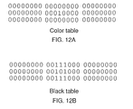
- FIG. 12A a color table, one bit is turned on.
- FIG. 12B identifies the surrounding bits, represented by 1's , that must be checked in the black table. If any one of the surrounding bits in the black table is on or a 1 , it signifies that there is a black block adjacent to a color block.
- the color and black tables can be used to quickly determine where color blocks are adjacent to black blocks.
- the next step is logically ANDing the neighbor byte with each byte in the black table that is located in the same column in the row above, the same row, and the row below the current byte in the color table.
- the result of each ANDing operation is called a mask.
- the resulting mask is a value not equal to zero, it indicates that there is a 1 or on bit in the black table (a "black bit") located adjacent the location that corresponds to the color bit.
- black bit represents a black block adjacent the color block represented by the color bit.
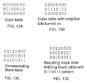
- FIG. 13A shows an excerpt from a color table, having a byte (in the second row) with two bits on.
- FIG. 13B shows the came color table with the left and right neighbor bits turned on (the neighbor byte).
- FIG. 13C shows the corresponding bytes in an exemplary black table.
- FIG. 13 D shows the resulting mask after logically ANDing each byte in the black table of FIG. 13 C with the neighbor byte of FIG. 13B.
- the step of creating a neighbor byte can be implemented at very high speed as follows. For each byte in the color table there are 256 possible combinations of bits, and there are 256 corresponding patterns of bits (or neighbor bytes) after the neighbor bits have been turned on. These neighbor bytes can be pre-computed and stored in an array (called neighborarray) having 256 entries. Each time the process detects one or more bits on in a color table byte, that color table byte can be used as an index into the neighbor byte array to look up the corresponding neighbor byte. This lookup procedure is represented by step 98 in FIG. 15, in which the neighbor byte array is called neighborarray.
- the first step 97 is to determine which bits in the color table actually represent color blocks rather than question mark blocks.
- the true color blocks are those blocks which have a corresponding bit on in the not in the black table. Therefore, by ANDing the color table byte with the complement of the corresponding black table byte 97 the true color blocks can be determined (called colorbyte ).
- the next step 98 is to fetch the neighbor byte for the current color table byte.
- a variable (called neighbor) is loaded with the appropriate neighbor byte from the look-up table ( neighborarray ) specified by the true color byte (colorbyte).
- This variable ( neighbor ) will be used to quickly determine whether there are any black blocks adjacent to the color blocks represented by the current byte in the color table.
- neighbor is logically ANDed with the black table byte in the same row/column location (blackTable[row][col]) to see if there are color blocks adjacent to black blocks.
- the result byte is called mask.
- fixBlack is a procedure that, for a given mask pattern and row/column pair in the color/black tables, moves the corresponding block of K plane data back into the CMY planes. For each block moved, the corresponding black table bit is turned off and the corresponding color table bit is turned on.
- the above technique does not address the case in which the "neighbor" bits to be examined in the black table are in a different byte to the left or right.
- the color table bit of interest (a "1") is at either end of the byte
- three of the "neighbor bits” in the black table are in a neighboring byte (adjacent the corresponding byte) and must be inspected explicitly.
- the leftmost bit of a color table byte is on, then the rightmost bit of the black table bytes to the left of, upper left of, and lower left of the corresponding byte in the black table must be checked.
- FIG. 14A shows a color table in which the leftmost bit of a byte is on.
- FIG. 14B shows the corresponding portion of a black table, in which the bits indicated with a "1" and numbered 200, 202 and 204 must be checked to see if the corresponding blocks contain black.
- FIG. 14C shows another color table in which the rightmost bit of a byte is on.
- FIG. 14D shows the corresponding portion of a black table, in which the bits indicated with a "1" and numbered 206, 208 and 210 must be checked to see if the corresponding blocks contain black. Accordingly, a procedure for checking adjacent bits must be able to cross byte boundaries in these special cases.
- any bit is on in a color table byte, it is necessary to detect every occurrence of a black table bit that is on adjacent the bit location in the black table that corresponds to the on color table bit.
- step 106 the indexes for the black table are [row-1] and [column-1]. This location corresponds to bit 200 in FIG. 14B.
- This byte in the black table is ANDed with the number 1 and the result checked for zero in step 106.
- the "mask” is a binary one, which is a byte with only the rightmost bit turned on. If the result of step 106 is False, the rightmost bit of this black table byte is on, adjacent to (above and left of) the leftmost bit of the color table byte. Accordingly, in step 108, fixBlack is called to move the corresponding black block to the CMY planes. If the result is True, the rightmost bit of this black table byte is off (zero), and we proceed to step 110 directly without calling fixBlack.
- step 128 (above and to the right); step 132 (same row - to the right); and step 136 (below and to the right).
- the procedure is similar to that employed for checking bytes to the left side, described above, so detail may be omitted. Note however that in FIG. 16 the adjacent bytes are ANDed with the number 128 so as to detect the leftmost bit in the blacktable byte, whereas the mask used in FIG. 15 was the number 1 to detect the rightmost bit. After checking each black table byte, the fixBlack procedure is called, as described above, to move data as necessary.
- the bytes above and below must be checked. More precisely, it remains to examine the black table bytes above and below the black table location corresponding to the current color table byte.
- mask is set to the value of neighbor logically ANDed with the byte from the black table above the color table byte.
- the black table index is set to [row -1][ col].
- the value neighbor corresponds, for example, to the byte shown in FIG. 13B. It is the current color table byte with neighbor bits turned on. If the corresponding black table bytes are as shown in FIG. 13C, the results after ANDing each black table byte with the neighbor byte are as shown in FIG. 13D.
- the next step 148 checks to see if the resulting value ( mask ) is equal to zero. If it is not equal to zero (False), there are black blocks adjacent to color blocks, and fixBlack is called with the appropriate values in step 150. The next step is to examine the black table byte below the color table byte. If the result of step 148 is True, we proceed to the next test without calling fixblack in step 150.
- the next step 152 is to set mask to the value of neighbor ANDed with the byte from the black table below the color table byte.
- the black table index is set to [row+1][ col].
- Step 154 checks to see if the resulting value is equal to zero. If mask is not equal to zero (False), there are black blocks adjacent to color blocks, and in step 156 fixBlack is called to correct the violation. If mask is equal to zero (True), the process is completed and stops 158.
- the method has checked all possible surrounding bits in the black table. For any black block adjacent to a color block, that black block was moved from the K plane back to the CMY planes, and the color and black tables updated accordingly. The foregoing procedures illustrated in FIGS. 15-17 are repeated for each byte in the color table that has at least one bit on.
- fixblack A preferred method of moving data from the black K plane back into the CMY color planes is arbitrarily called fixblack, as noted above. This method is illustrated in the flowchart of FIG. 18.
- the function fixBlack is passed three data - mask , row and col (column). Row and column are the address or index of the current byte. fixblack is called when that byte in the color and black tables represents black adjacent to color.
- the mask itself a byte, indicates (by a 1 ) which bit in the current byte represents the black block to be moved. More than one bit may be on in the mask.
- the row is checked to see if it is less than the top row of the current band. If so, then the corresponding band is marked as having new color 161.
- the new color flag indicates that black data was moved to color data in a previous band.
- the new color flag indicates that the pending band contains invalid data and must be reimaged before being issued to the printer for printing. The description of how the new color flag is used is described in detail below. As a result of the invalid data it is unnecessary to move the black data to the color data. Instead, just update the black table as shown in step 170 and the color table as shown in step 172, both explained below.
- bit is initialized to 128 in step 160, the leftmost bit of a byte.
- the bit will be shifted to the right, and at each shift, will be used to see if the same bit is on in the mask. If so, then the corresponding block that must be moved from the K plane to the CMY planes.
- Step 162 checks that the value of bit is still greater than zero. If so, bit is ANDed with the mask in step 164. If the result is not equal to zero (False), then in step 166 the K plane data represented by this bit in the black table is moved to the CMY planes.
- step 168 the bit value is shifted right by one, and the testing continues for the rest of the byte.
- step 170 the black table byte is replaced by itself logically ANDed with the binary complement of mask.
- step 172 the color table byte is ORed with the mask, thereby turning on the mask bits in the color table.
- findBlack refers to the procedures for finding and correcting adjacency violations, detailed above with reference to the flowchart of FIGS. 15-17.
- the methods called findBlack and fixBlack may be arranged to operate recursively, though that is not essential.
- the specific implementation is a matter of design choice, as long as processing continues until all minimum spacing violations are detected and corrected. Is some cases, as shown below, changing data can "propagate" over an entire page.
- the step of detecting spacing violations between black blocks and question mark blocks and propagating question marks is analogous to that of detecting spacing violations between black blocks and color blocks and propagating color.
- the findBlack routine has been modified to detect spacing violations between black blocks and question mark blocks.
- the method of propagating question marks begins in step 300 by identifying the question marks present in the byte specified by the row and column addresses.
- the question mark blocks are easily identified by those blocks which have the corresponding bits on in both the black table and the color table.
- the remainder of the method is identical to that of findBlack except that where findBlack called fixblack the method shown in FIGS.
- a spacing violation within the current band can not necessarily be resolved due to the possibility of color data in the next band within the predetermined distance from black data in current band. If the current band can not be resolved, i.e., there are question marks within the current band, all of the remaining question mark blocks are converted to black blocks and the current band is spooled to the secondary storage device. It is assumed that question marks will resolve to black because of the predominance of black on the printed page and also because of the desirability of printing in true black.
- the process for examining all of the spooled bands is shown in FIG. 20.
- the first step is to set the band to be examined to the oldest spooled band 228.
- This band is then examined for the existence of question marks 230 by examining the regions of the black and color tables that represent the band under examination. If the band has any question marks, they must have propagated up from subsequent bands (after the current band was spooled) and, therefore, all subsequent bands have question marks. It is then unnecessary to examine any other bands 232.
- By first checking for question marks we will never re-image a band that has question marks in it. This ensures that when a band is re-imaged, the black and color tables will be complete, and have no question marks.
- step 234 If the band under examination does not have any question marks, we check in step 234 to see whether any new color is present. What is meant by new color is that question marks that were assumed to be resolved to black were actually resolved to color. Therefore, the spooled data is erroneous and needs to be discarded.
- the spooled band must be re-imaged in step 236.
- the method essentially reenters the flowchart shown in FIG. 9 at step 201. Since the tables are fully and accurately reflect the requested band, the tables are "done" and the method can proceed to step 211. Fortunately, the color and black tables are correct and so the correct K-plane and CMY-planes can be quickly reassembled. After the planes are assembled they can be sent directly to the printer in step 213 for printing.
- the spooled band was spooled correctly and the spooled band is sent to the printer for printing in step 240. If the band is the last spooled band 242, the process is complete at step 244. Otherwise, the band to be examined is set to the next spooled band in step 246 and the sequence is repeated. In this way, all of the spooled bands are examined after each new band is received to determine if any have been resolved, and, if so, dispose of the band appropriately.
- the processing of the current band is quite simple.
- the first step in 248 is to determine whether there are any question marks within the current band. If there are question marks, the band must be spooled in step 250 to await subsequent bands. If the band is spooled to disk, the band is marked as processed in step 252, which is used to determine whether the band is "done" in step 209 of FIG. 9, and the processing of the current band is complete. If, however, there are no question marks in the current band, the band is sent directly to the printer in step 256 and the process complete.
- the final process step for each band received is removing the question marks from the tables in step 222.
- An expeditious method of removing the question marks is shown in FIG. 22.
- the process begins in step 262 by setting the row equal to the top row of the spooled band.
- the column is initialized by setting it equal to 1. If the column is less than the width of the black table, the current question byte is extracted from the tables by ANDing the color table byte and the corresponding black table byte in step 274. If the there are no question marks in the current question byte (step 276), the column is incremented in step 280 and the sequence is repeated.
- step 278 If, however, there are question marks in the current question byte, the question marks are eliminated by ANDing the current byte in the color table with the complement of the question byte in step 278. The method continues while the column is less than the width of the black table (step 266) and the row is less than or equal to the bottom row of the current band (step 268).
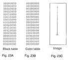
- FIGS. 23-25 illustrate an example of operation of the invention.
- FIG. 23C illustrates a graphics image.
- the vertical line is to be printed black.
- a circle indicating color ink At the lower end of the vertical line is a circle indicating color ink.
- the black line thus abuts the color ink.
- the black line In CMY color plane data, the black line would be represented as composite black, and the circle as the desired color.
- FIG. 23A shows the contents of a black table
- FIG. 23B shows the contents of a color table after this initial processing has been completed. Only a single bit remains on in the color table (row 12), indicating the color ink (the circle) in the image of FIG. 23C. A series of 1's in the black table now represent the vertical black line in the image. The initial table building corresponding to step 52 in FIG. 10 has been completed.
- step 146 (FIG. 17)
- step 146 (FIG. 17)
- mask 0011 1000 (neighbor) AND 0001 0000 (blackTable [row-1][col]).
- fixBlack is called to correct the minimum spacing violation.
- fixBlack is passed the mask to identify the offending table bit, and the table row and column locations.
- fixBlack receives the parameters: 0001 0000 (mask), 11 (row eleven), 1 (column 1 -- only one column in the example).
- fixBlack moves the corresponding block of data from the K plane back into the color planes, and updates the black and color tables accordingly (see FIG. 18).
- the bit directly above the color bit in FIG. 23B is turned on.
- the corresponding bit in the black table is turned off.
- Next findBlack is called, i.e. the procedure of FIGS. 15-17, to check the black table bits surrounding the new color table bit (in row 11) to detect black adjacent color once again.
- the black table bit in row 11 is now off, and is not at issue.
- But the black table bit in row 10 is detected as being adjacent the color table bit in row 11. Therefore, as before, the corresponding block of data is moved from the K plane back into the color planes.
- the tables are updated, i.e. the color table bit in row 10 is turned on, and the black table bit in row 10 is turned off.
- FIG. 24A black table
- FIG. 24B color table
- the data shown in the tables of FIG. 24 is represented by the image of FIG. 24C. Referring to FIG. 24C, the heavy (lower) portion of the vertical line represents composite black, while the finer (upper) portion of the line represents true black. This illustrates graphically how the composite black is "propagating" up from the color region.
- banded page to be printed is shown generally at 180 with band boundaries 182,184,186,188 drawn horizontally across the page.
- the page is comprised of five separate bands, i.e. Band 1-5, each not necessarily comprising the same amount of the page as the other.
- the actual number of bands used to comprise the page can vary as well.
- the bars 194 in Bands 3 and 4 are color.
- the vertical and horizontal lines, including the border around the bars, are black.
- the CMYK planes for Band 1 are brought into memory.
- the first step is marking blocks as black or color. There is only black data in Band 1, and there is no black data within a predetermined spacing from the band boundary, as indicated by broken line 190.
- the resulting black table has no blocks in the bottom row of the black table corresponding to band one. Therefore, this band is sent directly to the printer.
- Band 2 is treated the same way as band one, and is sent to the printer.
- Band 3 does contain both black and color data. After the black and color blocks are marked in Band 3, there are black blocks on the bottom row of the band in the black table. Note the border around the bar chart is black, and straddles the band boundary 186 (see 192). Question marks are placed on the black blocks at the bottom of the band.
- Band 4 is brought into memory.
- the black circle 196 that straddles Bands 4 and 5 at 188 causes question marks in two blocks, similar to the border in Band 3. After color and question marks have been propagated, color will have propagated back into band three (the color from the bars propagates to the border in Band 4, and continues up the border into band three). The data spooled to disk for Band 3 is incorrect, it assumed the border would be printed with true black, not composite black.
- This method now backs up to Band 3 and receives the CMYK planes again.
- the method keeps track of which bands have been spooled to disk.
- the color and black tables for this band are complete, and the method knows which inks should be used for the border around the color chart.
- the color table will show those blocks for border already marked as color, and will move the K data to the CMY planes so it will be printed as composite black.
Landscapes
- Engineering & Computer Science (AREA)
- Physics & Mathematics (AREA)
- Multimedia (AREA)
- Signal Processing (AREA)
- Mathematical Physics (AREA)
- General Engineering & Computer Science (AREA)
- General Physics & Mathematics (AREA)
- Theoretical Computer Science (AREA)
- Ink Jet (AREA)
- Record Information Processing For Printing (AREA)
- Facsimile Image Signal Circuits (AREA)
- Color Image Communication Systems (AREA)
Applications Claiming Priority (2)
| Application Number | Priority Date | Filing Date | Title |
|---|---|---|---|
| US07/954,787 US5475800A (en) | 1991-10-29 | 1992-09-30 | Color separation in color graphics printing with limited memory |
| US954787 | 1992-09-30 |
Publications (3)
| Publication Number | Publication Date |
|---|---|
| EP0590852A2 true EP0590852A2 (fr) | 1994-04-06 |
| EP0590852A3 EP0590852A3 (en) | 1994-05-18 |
| EP0590852B1 EP0590852B1 (fr) | 1997-08-06 |
Family
ID=25495930
Family Applications (1)
| Application Number | Title | Priority Date | Filing Date |
|---|---|---|---|
| EP93307475A Expired - Lifetime EP0590852B1 (fr) | 1992-09-30 | 1993-09-22 | Séparation de couleurs pour impression graphique en couleurs avec mémoire limitée |
Country Status (4)
| Country | Link |
|---|---|
| US (1) | US5475800A (fr) |
| EP (1) | EP0590852B1 (fr) |
| JP (1) | JP3319834B2 (fr) |
| DE (1) | DE69312840T2 (fr) |
Cited By (1)
| Publication number | Priority date | Publication date | Assignee | Title |
|---|---|---|---|---|
| EP0730247A1 (fr) * | 1995-03-01 | 1996-09-04 | Hewlett-Packard Company | Méthode d'impression à jet d'encre utilisant le renforcement en couleur dans les régions noires |
Families Citing this family (21)
| Publication number | Priority date | Publication date | Assignee | Title |
|---|---|---|---|---|
| US6064761A (en) * | 1993-03-08 | 2000-05-16 | Canon Information Systems Research Australia Pty Limited | Near black under color removal |
| US6116720A (en) * | 1993-10-28 | 2000-09-12 | Canon Kabushiki Kaisha | Ink jet recording method and apparatus for preventing color boundary blur |
| JP3029174B2 (ja) * | 1993-10-28 | 2000-04-04 | キヤノン株式会社 | インクジェット記録装置 |
| JPH07135575A (ja) * | 1993-11-12 | 1995-05-23 | Canon Inc | カラー画像情報出力装置 |
| US5553199A (en) * | 1994-05-03 | 1996-09-03 | Eastman Kodak Company | Method and apparatus for calibrating a four color printer |
| JP3175498B2 (ja) * | 1994-10-14 | 2001-06-11 | セイコーエプソン株式会社 | インクジェット式カラー印刷のための黒色領域識別方式 |
| US5975678A (en) * | 1994-10-27 | 1999-11-02 | Canon Kabushiki Kaisha | Ink jet recording apparatus and method using plural types of ink |
| US6259536B1 (en) * | 1995-12-27 | 2001-07-10 | Xerox Corporation | Color printing yielding a background dependent black image (i.e. intelligent black) |
| US5809215A (en) * | 1996-04-18 | 1998-09-15 | Lexmark International, Inc. | Method of printing to inhibit intercolor bleeding |
| US5739917A (en) * | 1996-07-12 | 1998-04-14 | Seiko Epson Corporation | Error-diffusion-type half-toning employing adaptive thresholding for enhanced smoothness |
| US5838885A (en) * | 1996-09-09 | 1998-11-17 | Seiko Epson Corporation | Salt-and-pepper-noise reduction |
| US5778160A (en) * | 1996-09-24 | 1998-07-07 | Xerox Corporation | Liquid ink printing system having region-dependent image processing |
| US5867179A (en) * | 1996-12-31 | 1999-02-02 | Electronics For Imaging, Inc. | Interleaved-to-planar data conversion |
| US6118548A (en) * | 1998-02-05 | 2000-09-12 | Canon Kabushiki Kaisha | Replacing true black with process black |
| JP4158310B2 (ja) * | 2000-03-31 | 2008-10-01 | ブラザー工業株式会社 | インク噴射装置の駆動方法およびその装置 |
| US20030081244A1 (en) * | 2001-10-30 | 2003-05-01 | Clouthier Scott C. | Method and apparatus for processing data in an imaging device |
| US7289243B2 (en) * | 2002-08-07 | 2007-10-30 | Lexmark International, Inc. | Apparatus and method for data compression optimized by print head architecture |
| US7246880B2 (en) * | 2004-10-29 | 2007-07-24 | Hewlett-Packard Development Company, L.P. | Method for black pixel designation in document image data |
| JP2008089804A (ja) * | 2006-09-29 | 2008-04-17 | Fujinon Corp | 撮像装置 |
| US8665482B2 (en) * | 2007-03-01 | 2014-03-04 | Konica Minolta Laboratory U.S.A., Inc. | Raster image processor using a self-tuning banding mode |
| DE102018201669A1 (de) | 2017-03-21 | 2018-09-27 | Heidelberger Druckmaschinen Ag | Verfahren zum Erhalt des Schwarzaufbaus von Objekten |
Family Cites Families (10)
| Publication number | Priority date | Publication date | Assignee | Title |
|---|---|---|---|---|
| US4682216A (en) * | 1983-03-08 | 1987-07-21 | Canon Kabushiki Kaisha | Color image picture forming process and apparatus which improves the quality of the black portions of the picture |
| US4958236A (en) * | 1987-06-11 | 1990-09-18 | Canon Kabushiki Kaisha | Image processing method and apparatus therefor |
| US4896275A (en) * | 1987-07-10 | 1990-01-23 | Bull Hn Information Systems Inc. | Full page graphics image display data reduction |
| JP2713935B2 (ja) * | 1987-12-29 | 1998-02-16 | キヤノン株式会社 | 画像処理方法 |
| JPH01228376A (ja) * | 1988-03-09 | 1989-09-12 | Minolta Camera Co Ltd | 階調表現方法 |
| US5012257A (en) * | 1990-03-16 | 1991-04-30 | Hewlett-Packard Company | Ink jet color graphics printing |
| US5283671A (en) * | 1991-02-20 | 1994-02-01 | Stewart John R | Method and apparatus for converting RGB digital data to optimized CMYK digital data |
| US5168552A (en) * | 1991-10-29 | 1992-12-01 | Hewlett-Packard Company | Color separation in ink jet color graphics printing |
| US5428377A (en) * | 1992-08-11 | 1995-06-27 | Xerox Corporation | Color spatial filtering for thermal ink jet printers |
| US5331438A (en) * | 1992-11-30 | 1994-07-19 | Xerox Corporation | Method and apparatus for improving full color images using process black and printer black |
-
1992
- 1992-09-30 US US07/954,787 patent/US5475800A/en not_active Expired - Lifetime
-
1993
- 1993-09-22 EP EP93307475A patent/EP0590852B1/fr not_active Expired - Lifetime
- 1993-09-22 DE DE69312840T patent/DE69312840T2/de not_active Expired - Fee Related
- 1993-09-30 JP JP26791993A patent/JP3319834B2/ja not_active Expired - Fee Related
Cited By (2)
| Publication number | Priority date | Publication date | Assignee | Title |
|---|---|---|---|---|
| EP0730247A1 (fr) * | 1995-03-01 | 1996-09-04 | Hewlett-Packard Company | Méthode d'impression à jet d'encre utilisant le renforcement en couleur dans les régions noires |
| US5821957A (en) * | 1995-03-01 | 1998-10-13 | Hewlett-Packard Company | Method of ink jet printing using color fortification in black regions |
Also Published As
| Publication number | Publication date |
|---|---|
| DE69312840T2 (de) | 1997-11-27 |
| US5475800A (en) | 1995-12-12 |
| DE69312840D1 (de) | 1997-09-11 |
| JPH06217119A (ja) | 1994-08-05 |
| EP0590852A3 (en) | 1994-05-18 |
| EP0590852B1 (fr) | 1997-08-06 |
| JP3319834B2 (ja) | 2002-09-03 |
Similar Documents
| Publication | Publication Date | Title |
|---|---|---|
| US5168552A (en) | Color separation in ink jet color graphics printing | |
| EP0590852B1 (fr) | Séparation de couleurs pour impression graphique en couleurs avec mémoire limitée | |
| JP3844791B2 (ja) | ディジタル画像の密度の調節方法 | |
| US7999971B2 (en) | Optimization techniques during processing of print jobs | |
| EP0862136B1 (fr) | Planarisation et piégeage de carte vectorielle | |
| US7692813B2 (en) | Image processing apparatus and method, and storage medium | |
| US7362467B1 (en) | Image processing device and image processing method thereof | |
| JP4215842B2 (ja) | カラー画像の印刷方法 | |
| US6429950B1 (en) | Method and apparatus for applying object characterization pixel tags to image data in a digital imaging device | |
| US8339667B2 (en) | Optimizing to-be printed objects during print job processing | |
| US6775410B1 (en) | Image processing method for sharpening corners of text and line art | |
| US6259536B1 (en) | Color printing yielding a background dependent black image (i.e. intelligent black) | |
| US6880907B2 (en) | Method of maintaining edge quality in ink jet printing | |
| US6445463B1 (en) | Image processing method to reduce marking material coverage in printing processes | |
| US20100165370A1 (en) | Laser print apparatus with toner explosion compensation | |
| US5930385A (en) | Apparatus and method for image conversion | |
| JPH08112917A (ja) | インクジェット式カラー印刷のための黒色領域識別方式 | |
| US6275302B1 (en) | Color printing yielding a background dependent neutral gray image (i.e. intelligent gray) | |
| US7536052B2 (en) | Corner sharpening of text and line art in a super resolution anti-aliasing image path | |
| US5848180A (en) | Color bitmap generation with background dependent black objects | |
| US7835046B2 (en) | Data processing apparatus, data processing method, computer program, and storage medium | |
| JP3636891B2 (ja) | カラー画像出力方法 | |
| JPS63242561A (ja) | フオント縮小システム | |
| JPH0781145A (ja) | 多色印刷装置 | |
| JPH0516435A (ja) | 画像形成装置 |
Legal Events
| Date | Code | Title | Description |
|---|---|---|---|
| PUAI | Public reference made under article 153(3) epc to a published international application that has entered the european phase |
Free format text: ORIGINAL CODE: 0009012 |
|
| PUAL | Search report despatched |
Free format text: ORIGINAL CODE: 0009013 |
|
| AK | Designated contracting states |
Kind code of ref document: A2 Designated state(s): DE FR GB IT |
|
| AK | Designated contracting states |
Kind code of ref document: A3 Designated state(s): DE FR GB IT |
|
| 17P | Request for examination filed |
Effective date: 19941024 |
|
| GRAG | Despatch of communication of intention to grant |
Free format text: ORIGINAL CODE: EPIDOS AGRA |
|
| 17Q | First examination report despatched |
Effective date: 19961202 |
|
| GRAH | Despatch of communication of intention to grant a patent |
Free format text: ORIGINAL CODE: EPIDOS IGRA |
|
| GRAH | Despatch of communication of intention to grant a patent |
Free format text: ORIGINAL CODE: EPIDOS IGRA |
|
| GRAA | (expected) grant |
Free format text: ORIGINAL CODE: 0009210 |
|
| AK | Designated contracting states |
Kind code of ref document: B1 Designated state(s): DE FR GB IT |
|
| REF | Corresponds to: |
Ref document number: 69312840 Country of ref document: DE Date of ref document: 19970911 |
|
| ET | Fr: translation filed | ||
| ITF | It: translation for a ep patent filed | ||
| PLBE | No opposition filed within time limit |
Free format text: ORIGINAL CODE: 0009261 |
|
| STAA | Information on the status of an ep patent application or granted ep patent |
Free format text: STATUS: NO OPPOSITION FILED WITHIN TIME LIMIT |
|
| 26N | No opposition filed | ||
| REG | Reference to a national code |
Ref country code: GB Ref legal event code: 732E |
|
| REG | Reference to a national code |
Ref country code: FR Ref legal event code: TP |
|
| REG | Reference to a national code |
Ref country code: GB Ref legal event code: IF02 |
|
| PGFP | Annual fee paid to national office [announced via postgrant information from national office to epo] |
Ref country code: IT Payment date: 20060930 Year of fee payment: 14 |
|
| PGFP | Annual fee paid to national office [announced via postgrant information from national office to epo] |
Ref country code: GB Payment date: 20070125 Year of fee payment: 14 |
|
| PGFP | Annual fee paid to national office [announced via postgrant information from national office to epo] |
Ref country code: DE Payment date: 20070228 Year of fee payment: 14 |
|
| PGFP | Annual fee paid to national office [announced via postgrant information from national office to epo] |
Ref country code: FR Payment date: 20070207 Year of fee payment: 14 |
|
| GBPC | Gb: european patent ceased through non-payment of renewal fee |
Effective date: 20070922 |
|
| PG25 | Lapsed in a contracting state [announced via postgrant information from national office to epo] |
Ref country code: DE Free format text: LAPSE BECAUSE OF NON-PAYMENT OF DUE FEES Effective date: 20080401 |
|
| REG | Reference to a national code |
Ref country code: FR Ref legal event code: ST Effective date: 20080531 |
|
| PG25 | Lapsed in a contracting state [announced via postgrant information from national office to epo] |
Ref country code: FR Free format text: LAPSE BECAUSE OF NON-PAYMENT OF DUE FEES Effective date: 20071001 |
|
| PG25 | Lapsed in a contracting state [announced via postgrant information from national office to epo] |
Ref country code: GB Free format text: LAPSE BECAUSE OF NON-PAYMENT OF DUE FEES Effective date: 20070922 |
|
| PG25 | Lapsed in a contracting state [announced via postgrant information from national office to epo] |
Ref country code: IT Free format text: LAPSE BECAUSE OF NON-PAYMENT OF DUE FEES Effective date: 20070922 |