EP0590936A2 - Appareil de commutation électrique avec déclencheur digitale et sélection de fréquence automatique - Google Patents
Appareil de commutation électrique avec déclencheur digitale et sélection de fréquence automatique Download PDFInfo
- Publication number
- EP0590936A2 EP0590936A2 EP93307679A EP93307679A EP0590936A2 EP 0590936 A2 EP0590936 A2 EP 0590936A2 EP 93307679 A EP93307679 A EP 93307679A EP 93307679 A EP93307679 A EP 93307679A EP 0590936 A2 EP0590936 A2 EP 0590936A2
- Authority
- EP
- European Patent Office
- Prior art keywords
- current
- samples
- per cycle
- power source
- count
- Prior art date
- Legal status (The legal status is an assumption and is not a legal conclusion. Google has not performed a legal analysis and makes no representation as to the accuracy of the status listed.)
- Granted
Links
Images


Classifications
-
- G—PHYSICS
- G01—MEASURING; TESTING
- G01R—MEASURING ELECTRIC VARIABLES; MEASURING MAGNETIC VARIABLES
- G01R19/00—Arrangements for measuring currents or voltages or for indicating presence or sign thereof
- G01R19/165—Indicating that current or voltage is either above or below a predetermined value or within or outside a predetermined range of values
- G01R19/16528—Indicating that current or voltage is either above or below a predetermined value or within or outside a predetermined range of values using digital techniques or performing arithmetic operations
-
- H—ELECTRICITY
- H02—GENERATION; CONVERSION OR DISTRIBUTION OF ELECTRIC POWER
- H02H—EMERGENCY PROTECTIVE CIRCUIT ARRANGEMENTS
- H02H3/00—Emergency protective circuit arrangements for automatic disconnection directly responsive to an undesired change from normal electric working condition with or without subsequent reconnection ; integrated protection
- H02H3/006—Calibration or setting of parameters
-
- H—ELECTRICITY
- H01—ELECTRIC ELEMENTS
- H01H—ELECTRIC SWITCHES; RELAYS; SELECTORS; EMERGENCY PROTECTIVE DEVICES
- H01H71/00—Details of the protective switches or relays covered by groups H01H73/00 - H01H83/00
- H01H71/74—Means for adjusting the conditions under which the device will function to provide protection
- H01H71/7409—Interchangeable elements
-
- H—ELECTRICITY
- H02—GENERATION; CONVERSION OR DISTRIBUTION OF ELECTRIC POWER
- H02H—EMERGENCY PROTECTIVE CIRCUIT ARRANGEMENTS
- H02H1/00—Details of emergency protective circuit arrangements
- H02H1/0007—Details of emergency protective circuit arrangements concerning the detecting means
-
- H—ELECTRICITY
- H02—GENERATION; CONVERSION OR DISTRIBUTION OF ELECTRIC POWER
- H02H—EMERGENCY PROTECTIVE CIRCUIT ARRANGEMENTS
- H02H3/00—Emergency protective circuit arrangements for automatic disconnection directly responsive to an undesired change from normal electric working condition with or without subsequent reconnection ; integrated protection
- H02H3/08—Emergency protective circuit arrangements for automatic disconnection directly responsive to an undesired change from normal electric working condition with or without subsequent reconnection ; integrated protection responsive to excess current
- H02H3/093—Emergency protective circuit arrangements for automatic disconnection directly responsive to an undesired change from normal electric working condition with or without subsequent reconnection ; integrated protection responsive to excess current with timing means
Definitions
- This invention relates to an electrical apparatus for connecting a load to either of a 50 Hz power source and to a 60 Hz power source, and in particular to electrical switching apparatus such as circuit interrupters and contactors having a digital trip unit, and more particularly, to such apparatus usable with both 50 Hz and 60 Hz power systems.
- Circuit breakers are widely used in industrial, commercial and residential applications for protecting electrical conductors and apparatus from damage due to excessive current flow. Initially used as direct replacement for fuses, circuit breakers have been gradually called upon to provide more sophisticated types of protection other than merely interrupting the circuit when the current flow exceeds a certain level. More elaborate time-current trip characteristics have been developed such that a circuit breaker can rapidly open upon very high overload conditions, but delays interruption upon detection of lower overload currents with the time delay being roughly inversely proportional to the degree of overload. Circuit breakers are also available which interrupt upon the detection of ground fault currents. As the complexity of electrical distribution circuits has increased, the control portions of the circuit breaker have been interconnected to provide selective coordination.
- solid state electronic control circuits were developed for use in high power, low voltage circuit breakers. These electronic control circuits performed functions such as instantaneous and delayed tripping which were traditionally achieved by magnetic-thermal means. The improved accuracy and flexibility of the solid state electronic controls resulted in their wide spread acceptance.
- circuit breakers must be compatible with the local power systems in different parts of the world. Thus, they must be adaptable for operating at a fundamental frequency of 50 Hz and 60 Hz.
- the capacitor discharges through a resistor selected to bleed the voltage off of the capacitor at a rate which mimics cooling of the load.
- Another approach has been to charge a memory capacitor when a trip occurs. The voltage on this capacitor is bled and read on power-up so that the microprocessor knows that the trip occurred and shortens the next trip time based on the time since the last trip.
- An object of the invention is to provide an electrical apparatus such as a circuit breaker or contactor converting a load to an ac-power source.
- an electrical apparatus for connecting a load to either of a 50 Hz power source and 60 Hz power source, said apparatus comprising separable contacts selectively connecting said load to the power source when closed and disconnecting the load from the power source when open, sensing means sensing current flowing through said separable contacts to the load when said contacts are close, digital control means including digitizing means digitally sampling said current sensed by said sensing means at selectable time intervals to generate digital current signals, means responsive to predetermined values of said digital current signals to generate a trip signal, and means responsive to said digital current signal to set said selectable time interval to operate said digitizing means to digitally sample said currents an equal number of samples per cycle for both a 50 Hz power source and a 60 HZ power source, and means responsive to said trip signal to open said contacts.
- digital means which digitizes the analog load currents at a sampling rate, synchronized to the ac power, of a selected odd integer number of samples per cycle of the ac power, and uses the digitized current samples to generate an rms value of the current for performing various protection functions.
- the selected odd integer number of samples per cycle is equal to the highest order odd harmonic selected to be detected in the currents plus 2.
- 15 samples per cycle are taken synchronously with the ac current to include the 13th harmonic. This reduces the sampling rate by almost half that called for under the Nyquist criteria previously used in these applications.
- the invention further includes means for automatically setting the sampling interval for synchronous sampling at the odd integer number of samples per cycle for both 50 Hz and 60 Hz power systems, so that the circuit breaker can be used with either frequency system without the need for manual adjustment. If this count exceeds a selected threshold, the circuit breaker is being powered by a 60 Hz source and the sampling interval is set accordingly. If the count is below the selected count, the interval is set for synchronous sampling of the 50 Hz source to which the breaker is connected. While this preliminary sampling could always be carried out using a fixed sampling interval, in the preferred embodiment of the invention, the sampling interval last used by the apparatus is employed. The known time period is selected as a fixed number of samples at the stored interval. If the interval for 60 Hz is used in the calculations, a first selected count is used, while a lower selected count is used if the 50 Hz interval is the stored interval.
- the present invention is responsive to the higher order harmonics needed for accurate tripping with present day non-linear loads while placing a much lower processing burden on the microprocessor than required by conventional digital switching units.
- the invention further provides automatic adjustment of the sampling interval to accommodate for both 50 Hz and 60 Hz power systems. This eliminates the need to stock two versions of the apparatus or the need for manual adaptation for the particular power source.
- Figure 1 is a isometric view of a circuit breaker with the rating plug shown removed from the casing.
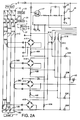
- FIGS 2A-C together illustrate a schematic circuit diagram of the circuit breaker of Figure 1.
- Figure 3 is waveform diagram illustrating the principle of operation of one aspect of the invention.
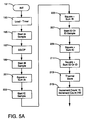
- Figures 4A-C illustrate a flow chart of a main program for the processor which forms part of the circuit breaker of Figure 1.
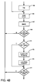
- Figures 5A and B illustrate a flow chart of an interrupt routine for digitizing currents monitored by the circuit breaker.
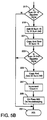
- Figure 6 is a flow chart of a routine for counting zero crossings.
- Figure 7 is a flow chart of a routine for selecting the sampling interval.
- the invention will be described as applied to a low voltage, four pole, molded case circuit breaker. However, it will be realized by those skilled in the art that the invention has application to other types of circuit breakers, and even to other types of electrical switching apparatus, such as electrical contactors including motor starters.
- the molded case circuit breaker 1 includes an insulated housing 3, formed from a molded base 5 and a molded cover 7, assembled at a parting line 9.
- the circuit breaker 1 is connected through line terminals 11A, B, C, and N to an electrical power system 13, and through load terminal 15A, B, C and to a load 17.
- Separable contacts 19A, B, C and N in internal conductors 21A, B, C, and N complete a circuit between the line terminals 11 and load terminals 15 when closed, and interrupt current flow to the load 17 when open.
- the contacts 19 are controlled by a circuit breaker mechanism 23.
- the operating mechanism 23 is actuated automatically by a shunt trip unit 27.
- the shunt trip unit 27 is controlled by signals applied to terminals 29 which are connected to an electronic trip unit 31.
- the heart of the electronic trip unit 31 is a custom integrated circuit 33 known as a SuRE Chip.
- the SuRE Chip incorporates a microcontroller core processor such as a Motorola MC68HC05-35 with 2K bytes of program memory and 128 bytes of user RAM 36.
- An additional 256 bytes of nonvolatile RAM (NVRAM) in the form of an EEPROM 37 are also provided.
- An 8-bit analog to digital converter subsystem 39 having a 6-input multiplexer and 4-bit prescaler provides a dynamic range of 12-bits with a conversion time of 48 ⁇ s.
- the SuRE Chip 33 provides all of the essential analog and digital functions in a single monolithic device.
- the electronic trip unit 31 provides a selection of protective functions. These include a hardware override trip, instantaneous protection, short delay protection, fourth-pole or ground fault protection (not shown), long delay protection, and over temperature protection. All except the override trip and over temperature protection are based upon true rms values of current.
- the electronic trip unit 31 includes current transformers 39A, B, C, N which generate secondary currents representing phase currents i A , i B i C and i N and neutral current i N flowing in the internal conductors 21A, B, C, N.
- the secondary currents generated by the current transformers 39 are fullwave rectified by on-board rectifiers 41A, B, C, N. Each of these rectifiers 41 produces a negative going voltage across a current sensing resistor 43A, B, C, N. In addition, each current flows through a capacitor 45 to develop 70 vdc power supply.
- Excess secondary current is bypassed by a FET 47 under control of the SuRE Chip 33 which monitors the 70-volt supply via sense circuitry composed of zener diode 49 and resistors 51 and 53 through the BSEN input.
- the SuRE Chip turns on the FET 47 through the BDR output.
- a circuit 55 which includes transistor 57 and capacitor 59 generates a 5 volt supply also under control of the SuRE Chip 33. Details of these supply and reference circuits are provided in the above referenced application on the SuRE Chip IC.
- Each of the negative going voltages across the resistors 43A, B, C, N is converted by a resistor 61A, B, C, N, respectively, into a current analog which is sourced from and digitized via SuRE Chip input MUXO, MUX1, MUX2, or MUX3.
- the four negative going voltages representing the phase current are auctioneered by the diodes 63A, B, C, N.
- a very large current in any phase will produce a very large negative going voltage at the common junction 65. This in turn will pull the CPO input to the SuRE Chip 33 below its threshold causing a hardware override trip.
- a voltage divider formed by the resistors 67 and 69 and zener diode 71 determines the secondary current level at which this occurs.
- This hardware override type feature provides protection against very large currents which must be interrupted immediately and cannot wait for the processing time of the SuRE Chip 33.
- the circuit breaker 1 mimics the heating of the load connected to the circuit breaker which includes the wiring. This includes cooling of this load after the current is interrupted. This feature prevents reenergizing the load until the digitally model heat state signal indicates that the load has cooled to a safe level.
- This digitally modelled heat state signal is a representation of I2t heating of the load.
- a memory capacitor 73 is forced to track the internal digital representation of I2t heating generated by the long delay trip function. This capacitor 73 stores an analog equivalent of the digital heat state signal. When the breaker trips and the SuRE Chip is deenergized, the thermal memory capacitor 73 discharges through the resistor 75.
- the value of the resistor 75 is selected so that the capacitor 73 discharges at a rate which models the cooling rate of the load.
- the internal digital representation of I2t heating is preset in proportion to any voltage remaining on the capacitor 73.
- the electronic trip unit 31 models the cooling of the load after a trip event. It may require several minutes before the load is cooled sufficiently that it may be reenergized. While this performs-a valuable protective function, it can be a nuisance when the circuit breaker is being tested or calibrated.
- the memory capacitor 73 can be charged to a preset value upon tripping of the circuit breaker.
- the resistor 75 bleeds charge on the capacitor 73 so that the decaying capacitor voltage provides a representation of time since the trip.
- the voltage on the capacitor is read by the microprocessor 35 and used to shorten the next trip time based on the time since the last trip.
- this memory capacitor performs an important protective function, but can be a nuisance during testing or calibration of the circuit breaker.
- a second resistor 77 is connected in parallel with the resistor 75 across the capacitor 73.
- the resistor 77 is connected to a test point terminal 79.
- the capacitor 73 can be rapidly discharged through the resistor 77, the value of which is selected to reset the memory capacitor 73 at a substantially more rapid rate than is effected by the resistor 77.
- test point terminals 83, 85 and 87 can be accessed to disable the long delay feature, verify the long delay trip threshold and the short delay trip threshold, through resistors 89, 91 and 93, respectively.
- the rating plug 95 has a resistor 97 which is connected through pin connections 99 between ground and an input MXO of the A/D converter 39.
- the resistor 97 when the plug is in place is in series with a resistor 101.
- the plug 95 is removably received in a recess 105 in the front panel of the circuit breaker 1 as seen in Figure 1.
- the frame size of the circuit breaker which is the maximum continuous current that the circuit breaker is designed to carry is established by the resistor 101. In a particular installation, it may be desirable to establish a maximum continuous current which is less than that permitted by the frame size.
- the removable rating plug 95 permits altering of this maximum continuous current by inserting the rating plug 95 with the appropriate valued resistor 97.
- a pair of rotary switches 107 and 109 permit the user to select one of eight settings for short delay or instantaneous pickup (current level), and short delay time, respectively.
- the switches 107 and 109 share a pull-up resistors 111 with the active switch being selected by the PC4 and PC5 outputs of the SuRE Chip 33.
- Synchronous serial input/output port (SSIOP) communications are available at SDO pin 113, SDI pin 115, SCK pin 117 and a ground pin 119.
- This link is capable of transmitting the entire contents of volatile and nonvolatile RAM and is also capable of accepting data for storage in EEPROM.
- This serial communications facility is used for factory calibration of the circuit breaker. During normal operation, the SSIOP periodically transmits two bits which identify the option selection and code version.
- the SuRE Chip 33 monitors the phase currents and the various parameter settings and generates, as appropriate, instantaneous, short delay, and long delay trip signals. It also generates a trip signal in response to the hardware override trip discussed above.
- the SuRE Chip 33 actuates the shunt trip 27 by turning on an SCR 121.
- the resistors 123 and 125 in capacitor 127 provide noise suppression for the SCR 121.
- a printed circuit board 129 on which the electronic components of Figure 2 are mounted is located under the cover 7 of the circuit breaker housing 3.
- the rating plug 95 has a stem 131 with a locking lug 133 on the end which extends through an opening 135 in the printed circuit board.
- the removable rating plug 95 is locked into the circuit breaker by inserting a screw driver in a slot 137 in the stem 131 and rotating the stem to engage the locking lug 133 in the circuit breaker.
- the pin connections 99 engage sockets (not shown) in the printed circuit board 129 to insert the rating resistor 97 into the circuit as described in connection with Figures 2A-C.
- test point terminals 79-87 are mounted on the printed circuit board 129 in alignment with the recess 105 in the front cover of the circuit breaker. Thus, these test points are only accessible when the rating plug 95 has been removed. Thus, for factory calibration or field testing of the memory feature, the rating plug 95 is removed and a jumper is placed between the test point terminals 79 and 81 to rapidly discharge the memory capacity 73.
- the secondary analog currents representative of the load and neutral phase currents are digitized by the analog to digital converter 39 for input to the SuRE Chip 33.
- the current practice is to sample the analog signals for digitizing at the Nyquist rate which is more than twice the frequency of the highest order harmonic to be detected.
- the above referenced paper suggests as that a sampling rate of 27 samples per cycle be taken to detect the thirteenth harmonic.
- sampling synchronously it is meant that the sampling interval is divisible into the fundamental frequency period an exact integer number of times, and since we are sampling an odd number of times per cycle, this integer must be odd.
- the phase of the sampling frequency can be random with respect to the fundamental frequency of the ac signal being digitized.
- the digitized current samples are utilized by the SuRE Chip 33 to generate digital rms currents. For instantaneous and short delay trips, fifteen samples (samples taken in one cycle) are used for the rms calculation. For the long delay trip calculation, 240 samples (samples taken over sixteen cycles), are used as more time is available to analyze the currents.
- the 240 sample rms values are transmitted over the SSIOP communications link to calibration equipment for use in the calibration procedure.
- the squaring and summing of each sample is accomplished during the 48 ⁇ s A/D conversion time of the next sample. Timekeeping relies upon the count of interrupts. All other tasks are performed in a main routine and are subject to interruption. To prevent the data that is being operated upon by the main routine from being modified by the interrupt routine (data tearing), the main routine operates only on data that was gathered during the previous cycle and buffered by the interrupt routine.
- Figure 4 illustrates a flow chart for the main routine run by the microprocessor 35.
- initialization tasks are performed at 147 and then the main loop is begun at 149.
- the routine waits at 151 until 15 current samples have been accumulated. If the breaker has not been tripped as determined at 153, the separate currents are scaled and the current of greatest magnitude is selected at 155.
- An instantaneous protection routine 157, a short delay protection routine 159, and, if provided, a ground fault protection routine 161 are called in sequence to set flags if the criteria for the instantaneous, short delay or ground fault trips have been exceeded.
- a trip signal is generated at 163 which turns on the SCR 121 to actuate the shunt trip mechanism 27, which opens the circuit breaker contacts 19.
- ROM checks and deadman checks are performed at 165 and 167, respectively.
- the main program cycles through the loop just described until 240 samples have been accumulated as determined at 169. If the breaker is not tripped as determined at 171, the appropriately scaled rms current calculated from 240 samples for the largest phase current is selected at 173 and used by the long delay protection routine at 175 to determine if the breaker should be tripped.
- the long delay protection routine 175 sets a trip flag which is implemented to generate a trip signal at 163 after 15 new samples have been accumulated. As this only represents one cycle, it is insignificant with respect to the long delay trip time.
- This larger loop is repeated until 960 samples have been accumulated as indicated at 177. When this occurs, the state of a status LED 178 on the front of the breaker (see Figure 1) is changed at 179. On alternate executions of this routine, the status LED 178 is turned on and off. As this routine is run about every second, the status light blinks on and off at this rate to provide an indication the circuit breaker is functioning.
- the SuRE Chip 33 has a diode (not shown) which is used to monitor the temperature of the chip.
- An over-temperature protection routine is run at 187 to check the temperature of the SuRE Chip and trip the circuit breaker if a temperature limit is exceeded.
- the last function implemented by the main routine is a sample time routine run at 189. This routine, which automatically determines whether the power system in which the breaker is connected is 50 Hz or 60 Hz, is described in connection with Figures 6 and 7.
- Figure 5 illustrates the interrupt routine for the main program. This routine is entered at 191 fifteen times per line cycle. Upon entering the interrupt routine, a timer is loaded is at 193 for generating the next interrupt. For 60 Hz, this interval is 1.111 ms, for 50 Hz it is 1.333 ms. The A/D conversion of the phase A current is then initiated at 195. While this is being carried out, serial communications are performed at 197. By this time, the A/D conversion of phase A is completed and digitizing of phase B current is initiated at 199. While this occurring, the phase A digitized current is squared and added to a sum of the phase A squared current at 201.
- phase C is initiated at 203 and the phase B current is squared and the result summed at 205.
- the neutral phase current or ground fault current if that option has been selected, is digitized at 207.
- the phase C and neutral or ground fault currents are then summed and the results squared at 209 and 211.
- the I2t heat state signal stored on the capacitor 75 is updated at 213. Counts for determining when 15 samples and 240 samples have been accumulated are then incremented at 215. Until the sum of squares of 15 samples has been accumulated as determined at 217, the routine returns to the program which was interrupted at 231.
- Figure 6 illustrates a short routine which is initiated by a zero crossing of one of the phase currents monitored, which in the exemplary circuit breaker is phase C.
- the positive zero crossings of phase C current generates an interrupt at 233 which increments a Z count at 235.
- the program then returns to the routine that was being run at 237.
- Figure 7 illustrates the sample time routine 189 in the main program.
- This routine called is every 960 samples (1.066 seconds). It automatically selects the correct sampling interval for the frequency of the power system in which the circuit breaker is being used.
- the monitored analog currents must be sampled synchronously at an odd number of samples per cycle. While different sampling rates could be used for 50 and 60 Hz power systems, these sampling rates must still be synchronous and generate an odd number of samples per cycle. It is convenient for the sake of the software to have the same odd number of samples per cycle generated for power systems of both frequencies.
- the sampling interval is 1.111 ms for 60 Hz and 1.333 ms for 50 Hz.
- the number of zero crossings in a known time period are counted.
- This known time period is selected to be long enough to easily discriminate between 50 Hz and 60 Hz line frequencies taking into account the possibility of miscounts and other anomalies.
- One possibility is to default the time interval to the value for either 50 Hz or 60 Hz and count the number of zero crossings occurring during a given number of sampling intervals.
- the interval last used by the circuit breaker which may be the value set during calibration for a new circuit breaker, is used in the determining the line frequency. The number of zero crossings during a fixed number of sampling intervals is then counted and compared with threshold values.
- the number of positive going zero crossing in 960 sample intervals is counted. For the 1.111 ms sample interval, 960 samples will occur in 1066.8 ms. The number of positive going 60 Hz zero crossings in this time period is 64 while the number of positive going 50 Hz zero crossings in this time period is 53. A count midway between these two counts is then selected to account for possible missed counts and other anomalies. In the exemplary system, the selected count is 59. If the positive going crossings exceed 59, the monitored signal is 60 Hz and a sample interval of 1.111 ms is selected. If the crossings are less than or equal to 59, the monitored signal is a 50 Hz signal and the sampling interval is set to 1.333 ms.
- the frequency test is run utilizing the 1.333 ms sampling interval, 960 samples will occur in 1280 ms. During this time interval, 64 positive going 50 Hz zero crossings and 76 positive going 60 Hz zero crossings will occur. Again, a count of 70 midway between these two counts is selected as the reference. If the positive going crossings exceed 70, the monitored signal is 60 Hz and the 1.111 ms interval is selected. If the crossings are less than or equal to 70, the 1.333 interval for 50 Hz signal is selected.
- Figure 7 illustrates a flow chart for the sample time routine.
- This routine is called at 239 by the main program at 189 each time 960 samples have been accumulated.
- the program is called at 239 in Figure 7, if the zero crossing count is less than 50, as determined at 241, the data is unreliable and the program is exited at 253. If the data appears to be reasonable, and the 1.111 ms sampling interval associated with 60 Hz power was used to generate the samples, as determined at 243, and the count of zero crossings is more than 59 as determined at 245, a 60 Hz signal is being monitored and the correct timing interval is being used. Hence, the program is exited at 253. However, if the count is less than or equal to 59, the monitored current is a 50 Hz signal and the 50 Hz interval of 1.333 ms is selected at 247.
- the monitor power is 50 Hz and the correct timing interval is being used.
- the 60 Hz timing interval of 1.111 ms is selected at 251.
Landscapes
- Physics & Mathematics (AREA)
- General Physics & Mathematics (AREA)
- Emergency Protection Circuit Devices (AREA)
- Breakers (AREA)
Applications Claiming Priority (2)
| Application Number | Priority Date | Filing Date | Title |
|---|---|---|---|
| US07/954,915 US5428495A (en) | 1992-09-30 | 1992-09-30 | Electrical switching apparatus with digital trip unit and automatic frequency selection |
| US954915 | 1992-09-30 |
Publications (3)
| Publication Number | Publication Date |
|---|---|
| EP0590936A2 true EP0590936A2 (fr) | 1994-04-06 |
| EP0590936A3 EP0590936A3 (en) | 1994-06-15 |
| EP0590936B1 EP0590936B1 (fr) | 1999-03-03 |
Family
ID=25496108
Family Applications (1)
| Application Number | Title | Priority Date | Filing Date |
|---|---|---|---|
| EP19930307679 Expired - Lifetime EP0590936B1 (fr) | 1992-09-30 | 1993-09-28 | Appareil de commutation électrique avec déclencheur numérique et sélection de fréquence automatique |
Country Status (5)
| Country | Link |
|---|---|
| US (1) | US5428495A (fr) |
| EP (1) | EP0590936B1 (fr) |
| JP (1) | JPH06203733A (fr) |
| CA (1) | CA2107319C (fr) |
| DE (1) | DE69323680T2 (fr) |
Cited By (5)
| Publication number | Priority date | Publication date | Assignee | Title |
|---|---|---|---|---|
| EP0686851A1 (fr) * | 1994-05-26 | 1995-12-13 | Eaton Corporation | Disjoncteur contrÔlé numériquement avec sélection automatique améliorée de l'intervalle d'échantillonnage pour des systèmes d'alimentation de 50 Hz et 60 Hz |
| KR100387004B1 (ko) * | 1994-12-22 | 2003-08-21 | 이턴 코포레이션 | 회로인터럽터및전류인터럽터 |
| WO2007134767A3 (fr) * | 2006-05-24 | 2008-03-13 | Friedrich Luetze Gmbh & Co Kg | Dispositif de mise hors circuit ou mise en circuit automatique d'un récepteur électrique |
| EP2778693A1 (fr) * | 2013-03-15 | 2014-09-17 | Rockwell Automation Technologies, Inc. | Appareil pour vérifier un état de sécurité au travail d'un système électrique |
| WO2017118558A1 (fr) * | 2016-01-05 | 2017-07-13 | Eaton Electrical Ip Gmbh & Co. Kg | Dispositif de commande pour un entraînement électromagnétique d'un appareil de commutation |
Families Citing this family (25)
| Publication number | Priority date | Publication date | Assignee | Title |
|---|---|---|---|---|
| US5734207A (en) * | 1994-05-06 | 1998-03-31 | Miklinjul Corporation | Voltage polarity memory system and fuse-switch assembly usable therewith |
| US6125023A (en) * | 1999-02-10 | 2000-09-26 | Bezek, Sr.; Donald J. | Circuit breaker receptacle |
| US6426634B1 (en) * | 1999-03-29 | 2002-07-30 | George A. Spencer | Circuit breaker with integrated self-test enhancements |
| US6310753B1 (en) * | 1999-11-05 | 2001-10-30 | Siemens Energy & Automation, Inc. | Low impedance magnetic latch tripping scheme |
| DE10027934B4 (de) * | 2000-05-31 | 2006-01-19 | Siemens Ag | Überstromauslöser für einen Niederspannungs-Leistungsschalter mit mindestens einem einstellbaren Kennwert |
| FR2832559B1 (fr) * | 2001-11-16 | 2004-01-16 | Schneider Electric Ind Sa | Module de commande et de protection d'un appareil interrupteur |
| EP1478985B1 (fr) * | 2002-02-25 | 2019-04-03 | ABB Schweiz AG | Modules d'echantillonnage de donnees et de transmission destines a des systemes de distribution electrique |
| US20040044486A1 (en) * | 2002-09-03 | 2004-03-04 | Tignor Michael S. | Non-linear electronics for sensing maximum dynamic range |
| US6921873B2 (en) * | 2003-08-01 | 2005-07-26 | Eaton Corporation | Circuit breaker trip unit employing a rotary plunger |
| US6853279B1 (en) * | 2003-08-01 | 2005-02-08 | Eaton Corporation | Circuit breaker trip unit including a plunger resetting a trip actuator mechanism and a trip bar |
| US6850135B1 (en) | 2003-08-01 | 2005-02-01 | Gaton Corporation | Circuit breaker trip unit employing a reset overtravel compensating rotary trip lever |
| US20050047045A1 (en) * | 2003-08-29 | 2005-03-03 | Puskar Michael P. | Circuit breaker and trip unit employing multiple function time selector switch |
| US7193827B2 (en) * | 2003-10-16 | 2007-03-20 | Square D Company | Single-sensor microcontroller-based approach for ground fault circuit interrupters |
| US7369389B2 (en) * | 2005-12-08 | 2008-05-06 | General Electric Company | Electronic trip unit for circuit breakers |
| DE102006011713A1 (de) * | 2006-03-14 | 2007-10-04 | Moeller Gmbh | Elektrische Auslöseeinheit für einen Motorschutzschalter eines Elektromotors |
| US8861156B1 (en) | 2006-04-04 | 2014-10-14 | Kent Jeffrey Holce | Status providing starter apparatus, system, and/or method |
| WO2007114951A2 (fr) * | 2006-04-04 | 2007-10-11 | Cerus Industrial Corporation | Appareil, système et/ou procédé pour protéger et commander un dispositif électrique |
| JP4998119B2 (ja) * | 2007-07-06 | 2012-08-15 | 富士電機機器制御株式会社 | 回路遮断器 |
| US7518475B2 (en) * | 2007-07-24 | 2009-04-14 | Eaton Corporation | Electrical switching apparatus, circuit interrupter and method of interrupting overcurrents of a power circuit |
| US8058751B2 (en) * | 2007-10-24 | 2011-11-15 | Eaton Corporation | Circuit interrupter and method of processor phase synchronization |
| US20090195337A1 (en) * | 2008-01-31 | 2009-08-06 | Carlino Harry J | Manually selectable instantaneous current settings for a trip unit and electrical switching apparatus including the same |
| US8610438B1 (en) * | 2012-08-09 | 2013-12-17 | Precision Air & Energy Services, LLC | Branch circuit monitor |
| US9368955B2 (en) | 2013-02-14 | 2016-06-14 | General Electric Company | System and method to derive power and trip a circuit breaker from an external device |
| DE102017211552A1 (de) * | 2017-07-06 | 2019-01-10 | Siemens Aktiengesellschaft | Elektronische Auslöseeinheit und Modul |
| DE102024205474A1 (de) * | 2024-06-13 | 2025-12-18 | Robert Bosch Gesellschaft mit beschränkter Haftung | System und Verfahren zum Verdrahtungsschutz |
Family Cites Families (11)
| Publication number | Priority date | Publication date | Assignee | Title |
|---|---|---|---|---|
| US4019097A (en) * | 1974-12-10 | 1977-04-19 | Westinghouse Electric Corporation | Circuit breaker with solid state passive overcurrent sensing device |
| US4025821A (en) * | 1976-03-10 | 1977-05-24 | Westinghouse Electric Corporation | Circuit breaker with improved trip means having a high rating shunt trip |
| US4331999A (en) * | 1980-04-15 | 1982-05-25 | Westinghouse Electric Corp. | Circuit interrupter with digital trip unit and power supply |
| US4428022A (en) * | 1980-04-15 | 1984-01-24 | Westinghouse Electric Corp. | Circuit interrupter with digital trip unit and automatic reset |
| US4420789A (en) * | 1982-04-19 | 1983-12-13 | General Electric Company | Characteristic timer for a protective relay |
| US4642564A (en) * | 1984-06-15 | 1987-02-10 | Cooper Industries, Inc. | Measuring circuit and method for power distribution equipment |
| US4631625A (en) * | 1984-09-27 | 1986-12-23 | Siemens Energy & Automation, Inc. | Microprocessor controlled circuit breaker trip unit |
| US4603313A (en) * | 1985-08-30 | 1986-07-29 | Westinghouse Electric Corp. | Circuit breaker with replaceable rating plug interlock and push to trip button |
| US5136458A (en) * | 1989-08-31 | 1992-08-04 | Square D Company | Microcomputer based electronic trip system for circuit breakers |
| US5060166A (en) * | 1989-12-06 | 1991-10-22 | Abb Power T&D Company Inc. | Method and apparatus for rapidly analyzing AC waveforms containing DC offsets |
| US5159519A (en) * | 1991-03-11 | 1992-10-27 | General Electric Company | Digital circuit interrupter with an improved sampling algorithm |
-
1992
- 1992-09-30 US US07/954,915 patent/US5428495A/en not_active Expired - Lifetime
-
1993
- 1993-09-28 DE DE69323680T patent/DE69323680T2/de not_active Expired - Fee Related
- 1993-09-28 EP EP19930307679 patent/EP0590936B1/fr not_active Expired - Lifetime
- 1993-09-29 CA CA 2107319 patent/CA2107319C/fr not_active Expired - Fee Related
- 1993-09-30 JP JP26978893A patent/JPH06203733A/ja active Pending
Cited By (9)
| Publication number | Priority date | Publication date | Assignee | Title |
|---|---|---|---|---|
| EP0686851A1 (fr) * | 1994-05-26 | 1995-12-13 | Eaton Corporation | Disjoncteur contrÔlé numériquement avec sélection automatique améliorée de l'intervalle d'échantillonnage pour des systèmes d'alimentation de 50 Hz et 60 Hz |
| AU695361B2 (en) * | 1994-05-26 | 1998-08-13 | Eaton Corporation | Digitally controlled circuit interrupter with improved automatic selection of sampling interval for 50 hz and 60 hz power systems |
| KR100387004B1 (ko) * | 1994-12-22 | 2003-08-21 | 이턴 코포레이션 | 회로인터럽터및전류인터럽터 |
| WO2007134767A3 (fr) * | 2006-05-24 | 2008-03-13 | Friedrich Luetze Gmbh & Co Kg | Dispositif de mise hors circuit ou mise en circuit automatique d'un récepteur électrique |
| EP2778693A1 (fr) * | 2013-03-15 | 2014-09-17 | Rockwell Automation Technologies, Inc. | Appareil pour vérifier un état de sécurité au travail d'un système électrique |
| US9234914B2 (en) | 2013-03-15 | 2016-01-12 | Rockwell Automation Technologies Incorporated | Apparatus to verify an electrically safe work condition |
| WO2017118558A1 (fr) * | 2016-01-05 | 2017-07-13 | Eaton Electrical Ip Gmbh & Co. Kg | Dispositif de commande pour un entraînement électromagnétique d'un appareil de commutation |
| CN108475603A (zh) * | 2016-01-05 | 2018-08-31 | 伊顿智能动力有限公司 | 用于开关设备的电磁驱动器的控制装置 |
| US10937616B2 (en) | 2016-01-05 | 2021-03-02 | Eaton Intelligent Power Limited | Control device for an electromagnetic drive of a switchgear |
Also Published As
| Publication number | Publication date |
|---|---|
| DE69323680T2 (de) | 1999-09-02 |
| CA2107319A1 (fr) | 1994-03-31 |
| DE69323680D1 (de) | 1999-04-08 |
| JPH06203733A (ja) | 1994-07-22 |
| EP0590936B1 (fr) | 1999-03-03 |
| US5428495A (en) | 1995-06-27 |
| EP0590936A3 (en) | 1994-06-15 |
| CA2107319C (fr) | 2005-05-24 |
Similar Documents
| Publication | Publication Date | Title |
|---|---|---|
| US5428495A (en) | Electrical switching apparatus with digital trip unit and automatic frequency selection | |
| EP0590937B1 (fr) | Appareil de commutation avec déclencheur numérique et remise à zéro d'une mémoire | |
| CA1330234C (fr) | Relais de surintensite avec moyen de signalisation | |
| US5311392A (en) | Dual processor electric power trip unit | |
| US5369356A (en) | Distributed current and voltage sampling function for an electric power monitoring unit | |
| US5559719A (en) | Digitally controlled circuit interrupter with improved automatic selection of sampling interval for 50 Hz and 60 Hz power systems | |
| CA2292088C (fr) | Methode et appareil d'essai d'un coupe-circuit de defaut d'amorcage d'arc | |
| JP2810786B2 (ja) | インテリジェント定格プラグを有するプロセッサ制御遮断器トリップ方式 | |
| CA1244929A (fr) | Disjoncteur a dispositif de declenchement numerique a semiconducteur a fonction de declenchement a temps inverse | |
| AU753319B2 (en) | Dual microprocessor electronic trip unit for a circuit interrupter | |
| CA2039704C (fr) | Systeme de disjonction a declenchement sur commande par processeur et active par panne | |
| CA2039698C (fr) | Dispositif de declenchement electronique a micro-ordinateur pour coupe-circuit | |
| US5335135A (en) | Fault recording system for an electric power trip unit | |
| JPS62160029A (ja) | 遮断器及び保護継電器装置 | |
| US5483408A (en) | Overcurrent trip unit with separately adjustable neutral protection | |
| US6696841B2 (en) | Electric power system relay and on-line method of testing same | |
| KR100434662B1 (ko) | 과부하 검출 회로 차단기 | |
| Carbajal et al. | An electric energy distribution systems protection microprocessor based relay |
Legal Events
| Date | Code | Title | Description |
|---|---|---|---|
| PUAI | Public reference made under article 153(3) epc to a published international application that has entered the european phase |
Free format text: ORIGINAL CODE: 0009012 |
|
| AK | Designated contracting states |
Kind code of ref document: A2 Designated state(s): DE FR GB IT |
|
| PUAL | Search report despatched |
Free format text: ORIGINAL CODE: 0009013 |
|
| AK | Designated contracting states |
Kind code of ref document: A3 Designated state(s): DE FR GB IT |
|
| RAP1 | Party data changed (applicant data changed or rights of an application transferred) |
Owner name: EATON CORPORATION |
|
| 17P | Request for examination filed |
Effective date: 19941130 |
|
| 17Q | First examination report despatched |
Effective date: 19970606 |
|
| GRAG | Despatch of communication of intention to grant |
Free format text: ORIGINAL CODE: EPIDOS AGRA |
|
| GRAG | Despatch of communication of intention to grant |
Free format text: ORIGINAL CODE: EPIDOS AGRA |
|
| GRAH | Despatch of communication of intention to grant a patent |
Free format text: ORIGINAL CODE: EPIDOS IGRA |
|
| GRAH | Despatch of communication of intention to grant a patent |
Free format text: ORIGINAL CODE: EPIDOS IGRA |
|
| GRAA | (expected) grant |
Free format text: ORIGINAL CODE: 0009210 |
|
| AK | Designated contracting states |
Kind code of ref document: B1 Designated state(s): DE FR GB IT |
|
| REF | Corresponds to: |
Ref document number: 69323680 Country of ref document: DE Date of ref document: 19990408 |
|
| ET | Fr: translation filed | ||
| ITF | It: translation for a ep patent filed | ||
| PLBE | No opposition filed within time limit |
Free format text: ORIGINAL CODE: 0009261 |
|
| 26N | No opposition filed | ||
| REG | Reference to a national code |
Ref country code: GB Ref legal event code: IF02 |
|
| PGFP | Annual fee paid to national office [announced via postgrant information from national office to epo] |
Ref country code: GB Payment date: 20050809 Year of fee payment: 13 |
|
| PGFP | Annual fee paid to national office [announced via postgrant information from national office to epo] |
Ref country code: DE Payment date: 20060929 Year of fee payment: 14 |
|
| GBPC | Gb: european patent ceased through non-payment of renewal fee |
Effective date: 20060928 |
|
| PG25 | Lapsed in a contracting state [announced via postgrant information from national office to epo] |
Ref country code: GB Free format text: LAPSE BECAUSE OF NON-PAYMENT OF DUE FEES Effective date: 20060928 |
|
| PGFP | Annual fee paid to national office [announced via postgrant information from national office to epo] |
Ref country code: IT Payment date: 20070915 Year of fee payment: 15 |
|
| PGFP | Annual fee paid to national office [announced via postgrant information from national office to epo] |
Ref country code: FR Payment date: 20070904 Year of fee payment: 15 |
|
| PG25 | Lapsed in a contracting state [announced via postgrant information from national office to epo] |
Ref country code: DE Free format text: LAPSE BECAUSE OF NON-PAYMENT OF DUE FEES Effective date: 20080401 |
|
| REG | Reference to a national code |
Ref country code: FR Ref legal event code: ST Effective date: 20090529 |
|
| PG25 | Lapsed in a contracting state [announced via postgrant information from national office to epo] |
Ref country code: IT Free format text: LAPSE BECAUSE OF NON-PAYMENT OF DUE FEES Effective date: 20080928 |
|
| PG25 | Lapsed in a contracting state [announced via postgrant information from national office to epo] |
Ref country code: FR Free format text: LAPSE BECAUSE OF NON-PAYMENT OF DUE FEES Effective date: 20080930 |