EP0590997A2 - Traitement de données d'image - Google Patents
Traitement de données d'image Download PDFInfo
- Publication number
- EP0590997A2 EP0590997A2 EP93307811A EP93307811A EP0590997A2 EP 0590997 A2 EP0590997 A2 EP 0590997A2 EP 93307811 A EP93307811 A EP 93307811A EP 93307811 A EP93307811 A EP 93307811A EP 0590997 A2 EP0590997 A2 EP 0590997A2
- Authority
- EP
- European Patent Office
- Prior art keywords
- colour
- lighting
- space
- polygon
- calculated
- Prior art date
- Legal status (The legal status is an assumption and is not a legal conclusion. Google has not performed a legal analysis and makes no representation as to the accuracy of the status listed.)
- Withdrawn
Links
Images


Classifications
-
- G—PHYSICS
- G06—COMPUTING OR CALCULATING; COUNTING
- G06T—IMAGE DATA PROCESSING OR GENERATION, IN GENERAL
- G06T15/00—Three-dimensional [3D] image rendering
- G06T15/50—Lighting effects
- G06T15/506—Illumination models
Definitions
- the present invention relates to apparatus and methods for processing image data.
- the present invention relates to apparatus and methods for processing image data for use in interactive 3-dimensional graphics environments.
- the present invention also relates to apparatus and methods for generating 2-dimensional representations of 3-dimensional objects, and to image signals and recordings resulting therefrom.
- the final 2-dimensional result may consist of a very large number of coloured picture elements (pixels) which may be viewed on a monitor or printed onto an image carrying medium.
- pixels coloured picture elements
- a machine In interactive systems arranged to generate data representing a 3-dimensional space, objects appear to move within the 3-dimensional space in response to input commands.
- a machine is required to render a 2-dimensional image from data representing a 3-dimensional space and, in addition, the machine is also required to perform this operation repeatedly as the position and/or orientation of objects, light sources and the view point change in response to input commands.
- the machine is required to produce output images at a rate of between five to fifteen per second. In more highly powered environments, output images are produced at video rate (60 frames per second) and the machine is said to operate in real time.
- the inventors have realised that a useful improvement in such systems can be obtained by incorporating a variation of saturation, as well as luminance in the range of each colour represented in the look-up table.
- the range of addresses (index values) associated with a particular colour begins by increasing in intensity (luminance) only, and subsequently decreases saturation until pure white is reached.
- the inventors have further found that since the increase in intensity and decrease in saturation are both associated with an increase in perceived brightness, relatively natural-looking effects can be maintained, even when the ambient, diffuse and specular illumination terms are combined into a single brightness value, which is then used (in combination with the colour selecting index) to address the colour look-up table.
- smooth shading across object primitives eg polygons
- the look-up table addresses may comprise for example three bits for colour selection and five bits for level of "brightness".
- some of the 256 entries are reserved for system use. In this case, it may be more efficient to divide the available range equally into a number of sub-ranges corresponding to the different colours.
- the brightness value can be added by binary addition to an offset value indicating the base of the appropriate sub-range.
- the invention further provides methods of processing image data in accordance with the principles of the invention as set forth above, and provides image signals and recordings, in whatever form, generated by means of such methods.
- FIG. 1 An environment for synthesizing 3-dimensional data, viewing 2-dimensional data derived from said 3-dimensional data and interactively modifying said 3-dimensional data is shown in Figure 1.
- a processor 15 is arranged to write data to and read data from a memory device 16.
- Data stored in the memory device 16 may define 3-dimensional image data, 2-dimensional image data, instructions to the processor 15 and other types of data which may or may not be relevant to interactive 3-dimensional graphics.
- 2-dimensional images are displayed on a visual display unit 18, which receives output image data at video rate, by raster scanning a frame buffer 19.
- the visual display unit 18 may have a definition of 1,000 lines with 1,000 pixels on each line, requiring frame buffer 19 to include 1,000,000 pixel locations.
- a mass storage device 20 is provided, such as a hard magnetic disk, optical disk or tape drive etc.
- processor 15, memory device 16, storage device 20, frame buffer 19 and the visual display unit 18 may be commercially available as a complete system.
- the configuration may consist of a Sparc workstation, supplied by Sun Microsystems Inc. of the United States.
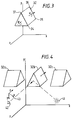
- 3-dimensional objects are defined in terms of a plurality of polygons. Each polygon is in turn defined as a plurality of connected points, referred to herein as vertices. Thus, objects are created by joining polygons, having coincident vertices along an edge common to both of the polygons.
- FIG 3 a simple object is shown, made up of five polygons. Data is stored in memory defining the position of each vertex of each polygon.
- polygon 32 has four vertices 34, 35, 36 and 37, the coordinates of which are listed in a table.
- the vertices of a polygon are defined in an order obtained by traversing around the polygon in an anticlockwise direction.
- Light sources are also provided and a viewing position is selected.
- Light sources model light falling upon the polygons, which in turn have lighting characteristics, that is to say, the polygons have colour and brightness responsive to the amount of light falling upon them and the nature of their surface.
- data is stored relating to a coefficient of ambient light K(a), a coefficient of diffuse light K(d) and a coefficient of specular light K(s).
- the 3-dimensional image data in object space undergoes a local transformation which transforms objects into modelling space, at step 21.
- the polygon surfaces are lit by processing data relating to the position of light sources in modelling space and the lighting parameters of each polygon.
- the modelling space is transformed into a viewing space, the geometry of which differs depending upon whether an isometric view or a perspective view is required.
- step 25 data processed by the processor and read from the memory defines 3-dimensional coordinate locations.
- the projected view is analyzed to define an image in 2-dimensions, thus, in isometric views, the z dimension is rejected and in perspective views the x and y dimensions are scaled, so as to take account of the rejected z dimension.
- the 2-dimensional data relating to polygon position is scan converted to produce coloured pixels, taking into account data defining the colour of each polygon, as previously calculated.
- the pixels are written to the frame buffer on a polygon-by-polygon basis, thereby building up a complete 2-dimensional image. It should be noted that images must be written to the frame buffer at a rate of between ten to fifteen frames per second in order that a viewer will feel that the system is responding in an interactive way to input commands.
- a representation of modelling space is shown in Figure 4.
- World coordinate axes X, Y and Z have a similar orientation to the axes provided in object space, as shown in Figure 3, but may be scaled differently. For example, it may be appropriate, under default conditions, to define objects as being relatively large in object space and relatively smaller in modelling space, so that a plurality of objects may be assembled in modelling space.
- Transformations from an object space, such as that illustrated in Figure 3, to a modelling space, such as that illustrated in Figure 4, are effected by matrix manipulation.
- the coordinate positions of, say, points 34, 35, 36 and 37 are multiplied by a transform matrix which replaces coordinates within the object space of Figure 3 with coordinates of modelling space as in Figure 4.
- Three instantiations of the object are placed into modelling space by using three different matrix transforms.
- additional objects may be placed into modelling space by effecting transformations upon other objects defined in their own object space.
- Light sources may be introduced into the modelling space which, in addition to having position, also have orientation. Furthermore, parallel light may be introduced into the modelling space, representing the effect of light emanating from an infinitely displaced source, similar to light produced by the sun. The effect of each light source is considered in turn and lighting effects for each source are added together on a polygon-by-polygon basis.
- a viewing position 42 is also selected, illustrated by an eye symbol.
- the viewing position may, alternatively, be represented by a set of axes x, y, z 43, given that a transformation from modelling space as shown in Figure 4, consists of transforming objects into a new space, which has a different set of axes.
- a transformation from modelling space as shown in Figure 4
- the origin is at the back bottom left
- the origin is at the front bottom left or front top left.
- the z direction represents distances measured away from the viewing position.
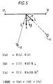
- Lighting calculations for polygon 32b will be considered, with reference to Figure 5.
- the lighting calculation produces an illumination factor I which, in a colour system, consists of colour components RGB.
- the value I(RGB) representing the total illumination factor for the polygon consists of an illumination factor I(a) from ambient lighting, a component I(d) from diffuse lighting from a light source and a component I(s) for specular lighting from said light source.
- I(a) is derived from the background ambient lighting B(a) and is obtained by multiplying this value by the ambient coefficient K(a), as shown in Figure 5.
- I(d) and I(s) are dependent upon the position and intensity of the light source 41 and, in accordance with the Phong model, I(s) is dependent upon the position 42 of the observer.
- the Phong model is convenient in systems of this type, although other models are known.
- the diffuse component I(d) is derived from the cosine of the angle theta between a vector pointing towards the light source 41 and a vector normal to the plane. Its value is calculated by the scalar or "dot" product of the unit normal vector N and a unit vector L pointing in the direction of the light source 41.
- the component I(d) is obtained by multiplying a value identifying the intensity of the light emitted by the light source 41 I(1) by the dot product of vectors N and L by the coefficient K(d).
- the intensity of specular highlights is dependent upon the position of the viewer 42.
- a unit vector H is calculated which is half way between the unit vector L and a unit vector E , directed towards the position of the viewer 42.
- the dot product is then formed between the unit normal vector N and the unit half way vector H .
- the model is arranged such that the specular highlight is large when vectors E and L form similar angles to the plane 36, 37, thus resulting in vectors N and H being coincident. Moving away from this position results in the intensity of the specular highlight decreasing rapidly.
- the dot product of the H and N is raised to a power, typically lying within the range 15 to 20 or higher. This value is then multiplied by the coefficient K(s) and the intensity value I(l).
- Raising the dot product of H and L to a power is a computationally expensive process, therefore the inclusion of means for calculating specular high lights is a significant overhead and in many systems is not included.
- specular highlights add significantly to the realism of the object and allow distinctions to be made between shiny and matt surfaces.
- step 23 a view transformation is made, taking account of the view position 42. It should be noted that, in response to interactive input, the view position 42 may be interactively modified, therefore in the same way in which local transformations and the lighting of surfaces are performed at the interactive rate, view transformation is also performed at the interactive rate.
- a viewing transformation consists of defining the viewable space and shifting the axes.
- polygons will lie outside the viewable space. These polygons are identified by comparing their x, y and z coordinates with the coordinates of the viewable space, resulting in a list of polygons which will require further processing.
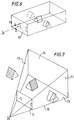
- the unit normal vectors are also transformed.
- the front polygon has a unit normal vector extending in the negative z direction of the view coordinates
- the back face has a normal vector extending in the positive z direction.
- back face culling is performed by rejecting all polygons which have a unit normal vector with a positive z component.
- the unit normal vectors are used at both step 22 when calculating lighting and at step 26 when back face culling. Consequently, the unit vectors are transformed under the local transformation at step 21 and under the view transformation at step 23. Furthermore, these transformations will often produce normal vectors which are no longer of unit length. Consequently, it is necessary to re-normalise these vectors so that, in accordance with the coordinate system being used, they are re-established as normal vectors of unit length. Again, this is computationally expensive, given that square roots must be calculated for each polygon in order to calculate the x, y and z components of the transformed vector, having overall unit length.
- step 27 consists of scan converting the polygons to produce pixel values.
- the x-y coordinates in the 2-dimensional projected plane define the positions of pixels within the frame buffer.
- the x and y coordinate positions typically lie over a range of 0 to 1,000 in both the x and y dimensions, from an origin at the top left corner.
- Scan conversion is initiated by identifying which vertex of the polygon has the smallest y value, in this case, vertex 101.
- pixels within the polygon are filled-in starting from this point by calculating the gradients to vertices 102 and 103, which are located at positions (1, 8) and (12, 6) respectively.
- This data is then written to the frame buffer at step 28.
- Hardware savings can be made by reducing, wherever possible, the level of data movement and data processing. It should be noted that, when a modest amount of processing is being performed on a large amount of data, even the modest process of moving data from one location to another or comparing a stored value with another value results in a significant overhead, if all of the data under consideration must be moved in this way.
- the object is to reduce the number of physical processors required to implement the necessary process steps. Each saving is significant and if a sufficient number of savings can be made, the whole process can be carried out on a common serial processor.
- object culling is performed by determining, after local transformation and viewing transformation, the extent to which an object can actually be seen. Extents are defined for the object in each dimension, that is to say, maximum and minimum values are determined for the object in each of the X, Y and Z dimensions.
- This process effectively defines a bounding volume in the form of a cuboidal bounding box of planes of constant X, Y or Z extent.
- bounding volume may conveniently be employed.
- a bounding sphere can be defined very economically be reference only to the coordinates (X, Y, Z) of its centre and the magnitude of its radius.
- step 113 the lighting of polygons, where necessary, is performed.
- a local transformation is performed at step 21; surfaces are lit at step 22 and a view transformation is effected at step 23.
- the local transformation and the view transformation are mathematically similar and, when performed by matrix multiplication, the matrices defining the transformations may be concatenated into a common matrix.
- the local transformation and the viewing transformation are performed as one transformation from object space to viewing space, again significantly reducing the computational overhead.
- this is effected by calculating the inverse to the local transformation, effecting this inverse transformation upon the position of light sources, thereby effectively transforming the light sources into object space. Thereafter, lighting calculations are performed in object space and the object is transformed directly from object space to viewing space, using the concatenated matrix.
- the concatenated matrix used to transform the bounding box during the object cull, at step 111 is used again to transform the actual object polygons from object space into viewing space at step 114.
- Step 115 is substantially similar to step 24 in Figure 2 and involves the clipping of polygons which do not lie within the viewing space. However, as previously stated, additional information is generated at step 111 during the object culling process which identifies planes for viewing space through which objects intersect. This information facilitates the polygon clipping process at 115, thereby again reducing computational overhead to effect this part of the procedure.
- the projection into a 2-dimensional image at step 116 is substantially similar to the projection process performed at step 25.
- back face culling is performed, as required at step 26 of Figure 2 but this procedure is performed without reference to the polygon normals, which are only used in the present embodiment within object space and are not transformed into other spaces, again reducing computational overheads.
- other methods must be provided to perform back face culling at step 117, as described later.
- Step 118 provides scan conversion and computational overhead for this process is reduced by taking account of the restricted depth of most frame buffers, typically only having eight bits per pixel location. Thereafter, a 2-dimensional video image is produced in similar fashion to the system shown in Figure 2 by raster scanning the frame buffer at video rate.
- an object is initially defined in its own object space, as shown in Figure 3.
- Data stored in memory actually consists of a table of vertices defined with reference to the X, Y and Z coordinates.
- the object culling process at step 111 consists of examining X, Y and Z coordinates so as to identify the extent of the vertices for an object in each dimension, that is to say the maximum and minimum value in each dimension is determined. From these extents, a bounding volume in the form of a box is defined, as shown in Figure 12.
- plane 121 represents the maximum extent in the X direction and the plane opposite plane 121 represents the minimum extent in X.
- plane 122 represents the maximum extent in Y and plane 123 represents the maximum extent in Z.
- object 32b is completely within the viewable area.
- Object 32a is completely outside the viewable area and object 32c is partially inside and partially outside.
- the object 32c falls within a bounding box which is partially inside the viewing area and partially outside the viewing area.
- culling must be performed on a polygon basis.
- the fact that this object requires polygon culling is supplied to the polygon clipping process at step 115.
- any other bounding shape may be used. It should also be noted that it may not always be desirable to reject objects before transforming them into modelling space when they are outside the viewable portion of that space, for example because they are required to cast a shadow on other objects which are visible.
- the bounding volume test may still be useful to select objects for rejection before other aspects of further processing, however, for example to prevent effort being wasted to calculate lighting characteristics of the objects themselves.
- step 112 changes are noted in light source parameters and changes are also noted in object positions. If a light source parameter and an object's orientation or position have not changed, it is not necessary to recalculate lighting characteristics for that particular object. Thus, lighting characteristics previously calculated are retained and used again.
- data is stored defining the position of light sources, a viewing position and an arrangement of polygons defining an object.
- a local transform defines how an object positioned in its own object space is transformed into viewable 3-dimensional space. This may be referred to as modelling space and the system is arranged such that the viewer is given the illusion of moving around within this modelling space.
- a transformation of the unit normal vectors into modelling space usually results in said vectors no longer being of unit length. Consequently it would be necessary to re-normalize said vectors, which represents a significant computational overhead.
- said normal vectors do not need to be transformed into modelling space for the purpose of calculating lighting.
- the overhead of performing this transformation is lost along with the even greater overhead of performing the re-normalisation process.
- the present embodiment also permits culling of back facing polygons after projection into viewing space, but without the need for projected surface normal vectors.
- the Phong model for calculating specular reflection is detailed in Figure 5 and, as shown, it is necessary to calculate the dot product of the unit normal vector N with a unit vector H positioned half way between the vector L , directed towards the light source 41, and a vector E , directed towards the viewing position 42.
- implementing the Phong model is computationally expensive, given that the H vector must be calculated and the dot product of H with N must then be raised to a power.
- calculation of the H vector involves transforming the viewing position into object space and then performing additional calculations in order to determine the position of said vector.
- the present embodiment makes use of this observation, in that lighting characteristics are calculated in response to lighting parameters of surfaces and the parameters of light sources, without making reference to the viewing position.
- a lighting parameter is non-linearly processed to simulate highlight characteristics, without reference to the view position.
- the specular characteristic is calculated by raising the dot product of N with L to a power n, in which n represents the specularity or shinyness, of the polygon under consideration.
- the specular calculation is only performed for polygons having a significant specular component.
- K(s) falls below a particular threshold it is not necessary to perform the specular calculations.
- means are provided for calculating the position of objects in space in high accuracy floating point arithmetic.
- lighting characteristics are calculated using lower accuracy fixed point arithmetic.
- the limitations of fixed point arithmetic are tolerated because results are still produced which are more accurate than the accuracy of values supplied to the frame buffer, therefore truncation is still required.
- the rate at which fixed point arithmetic may be performed is substantially higher than the rate of performing floating point arithmetic, thereby reducing computational demands.
- the first point at which conversion from floating point to fixed point is required is when the normal to the polygon (or vertex) is pre-calculated.
- the algorithm is straightforward: carry out all calculations in floating point until the final values are ready for storage, then (and only then) convert the values to fixed point numbers. In some embodiments this will impose a restriction upon the coordinate system of the 3d world thus handled, in that no coordinate can exceed the largest number representable in the chosen fixed point numeric range.
- the inverse transform of the light vector (lighting direction), with respect to the local transform of the object, is calculated in floating point to produce a floating point 3-vector.
- the inverse transformed position of the light is also calculated (also using floating point arithmetic). Then the inverse transformed direction vector is converted from floating point to fixed point, Likewise the position, for point and conical lights.
- the normal to the polygon (in the case of facet shading) or the normal to the vertex (in the case of vertex shading) has been precalculated in fixed point, and this is combined with the converted lighting vector in the traditional way to produce a fixed point coefficient of illumination.
- the coefficient of illumination is converted into a colour value (palette index or RGB triple) and stored as the colour of the polygon.
- the illumination coefficient for the vertex is stored, as an integer. Interpolation to obtain per-pixel colour values can then be performed in fixed point or integer arithmetic, to achieve a significant saving. In both cases the only final stage conversion required is that of fixed point number to integer, a relatively trivial operation.
- the process of scan conversion involves selecting the vertex 101 which has the minimum y coordinate, that is to say, it is the vertex which is closest to the top of the viewing screen.
- point 103 will be listed prior to point 101, which in turn will be listed prior to point 102.
- the vector connecting point 101 to point 102 should always be to the left of the vector connecting point 101 to point 103, when the polygon is front facing.
- the gradient that is to say the rate at which x changes with y
- the gradient will always be greater (more positive) for the vector connecting vertex 101 to vertex 103 than the similar gradient for the vector connecting vertex 101 to vertex 102, when the polygon is front facing.
- the gradient of the vector connecting the highest (minimum y value) vertex to its preceding vertex is less than or equal to the gradient connecting said highest vertex to its succeeding vertex, the polygon is to be culled. This is because it is either back facing or it is on edge, neither of which should be rendered.
- the coordinates (6, 2) (1, 8) and (12, 6) are shown in Figure 10 as the x, y positions of the vertices 101, 102 and 103.
- the vector connecting vertex 101 to vertex 102 represents a decrease of 5 in the value of x, for an increase of 6 in the value of y. This corresponds to a gradient of -5/6.
- the vector connecting vertex 101 to vertex 103 represents an increase of 6 in the value of x, for an increase of 4 in the value of y. This translates to a gradient of -6/-4 or 3/2. This is greater than the other gradient -5/6, confirming that the polygon is forward facing.
- the gradients thus calculated are not wasted, in that they are useful for the operation of scan conversion, to be described below.
- the calculated gradient can be stored and used for both polygons.
- the trivial case of Figure 10 can be confirmed as a front facing polygon without calculating the gradients, by observing that from vertex 101 to vertex 103 the value of x decreases, while from vertex 101 to vertex 103 the value of x increases. This confirms that one gradient is less than zero while the other is greater than zero, such that the one must be greater than the other. Only when both gradients are of the same sign is it necessary to perform the division and calculate the gradient. On the other hand, in an embodiment where the gradients are anyhow required for scan conversion, this pre-test on the basis of signs alone will not save any computation.
- z component of the vector or "cross" product of vectors connecting points 103 to 101 and 101 to 102 is calculated.
- Such an approach is similar to transforming the normal vectors, as previously performed.
- the magnitude of the vector is irrelevant and only its direction in the z dimension is required, thereby making the calculation less intense than that required for re-normalization.
- a partial cross product is calculated to identify the z component of a normal vector in screen space and the polygon is culled if the vector calculated in this way points into the screen.
- the first vector has components (-6, -4) and the second vector has components (-5, 6), in accordance with the ordering of the vertices 103, 101, 102. Representing these as (x1, y1) and (x2, y2) respectively, the z component of the cross product is defined as x1y2 - x2y1. In the present example this results in -36 - 20, which equals -56. Since this is a negative z value, pointing out of the screen, the polygon is front facing.
- the back facing test based on the projected vectors employed in the present embodiment automatically takes into account perspective effects included in the viewing transformation.
- the side faces of the object are clearly identified as back facing in the viewing space, whereas in the modelling space without perspective correction ( Figure 6) these faces are parallel to the viewing direction.
- step 116 the 3-dimensional view is projected to define an image in 2-dimensions, wherein each vertex is given a 2-dimensional coordinate position.
- step 117 back face culling is performed as previously described so that, at any position on the screen, only one polygon is present, thereby uniquely defining the characteristics of that position.
- Step 118 consists of scan conversion, which involves specifying which pixels are required to be modified to define a particular polygon and, additionally, to specify a colour for those particular pixels.
- the process for identifying which particular pixels are to be included within a polygon is substantially similar to the process employed in the conventional system and as described with reference to Figure 10.
- the process is also described in the applicants co-pending European Patent Application EP-A-0531157 (not published at the present priority date) included herein by reference as part of the present disclosure.
- each pixel location within the frame buffer 19 stores eight bits and, as previously stated, in the present embodiments, lighting characteristics are calculated using fixed point arithmetic, although these fixed point values will still require further truncation before being written to the frame buffer 19.
- 2-dimensional image data is produced, wherein pixels in 2-dimensional areas are coloured in response to calculated lighting characteristics, representing the colour of said areas. Pixel colours are stored in a look-up table, which is addressed by values read from the frame buffer.
- values stored in the frame buffer have a predetermined number of bits representing colour hue and a predetermined number of bits representing another characteristic of the selected colour.
- the eight bit addresses to the look-up table are arranged such that three bits identify hue and the remaining five bits represent another characteristic of the selected hue.
- a total of eight hues may be provided, selected from the gamut of colours which may be realised by the VDU 18.
- hues such as blue, red, green, magenta, cyan and yellow may be selected and the system may be considered as having a separate five bit look-up table for each of said selectable hues.
- the remaining five bits define one of 32 luminance levels.
- linear interpolation between colours is not possible and colour aliasing occurs.
- luminance is controllable over a 32 bit range, which produces results of acceptable quality, given that the eye is more sensitive to luminance aliasing.
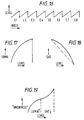
- a colour ramp for an alternative example is shown in Figure 17. It should be noted that this colour ramp is repeated eight times, in a similar fashion to Figure 16, once for each selectable colour.
- FIG. 18 Another alternative colour ramp is shown in Figure 18 which again would be repeated eight times as shown in Figure 16.
- the other characteristic of a selected colour is saturation.
- the colour ramp may initiate at a fully saturated colour value, with a predetermined amount of luminance and, as input values increase, the saturation decreases, so that the output colour fades from a distinct colour towards white.
- specular highlights may be calculated by raising the dot product of N and L to a power.
- it may only be necessary to calculate the dot product without raising it to a power because the non-linear raising to a power may be performed by the look-up table, when pixel values stored in the frame buffer are converted to real colour signals.
- a specular highlight process may perform easily implemented power raising (to the power 16 say) with further non-linearity being introduced by the look-up table.
- FIG 19 A yet further alternative embodiment for the colour ramps is shown in Figure 19, which combines the luminance characteristic of Figure 17 with the saturation characteristic of Figure 18.
- three bits select one of the eight available hues. The remaining five bits represent the level of lighting applied to the surface. Initially, luminance values start at zero and the object is represented as black. As the lighting value increases, the luminance value increases and saturation remains high, such that a red area, say, gets brighter but remains red, representing the effect of diffuse reflection, until at about half way, or preferably further, luminance reaches its maximum value.
- each ramp undergoes a change from black to full colour to white, wherein a different colour is provided for each ramp.
- the luminance region varies non-linearly to take account of gamma correction and the saturation region varies non-linearly to represent specular reflection.
- either or both of these ramps could be linear.
- Figure 20 illustrates separately the green (G) blue (B) and red (R) components stored in the colour look-up table for one of the colour ramps.
- the colour ramp illustrated in Figure 20 corresponds to the colour cyan, which is chiefly composed of green and blue components, with little or no red.
- an increase in the look-up table index over the range of the cyan colour ramp causes a change from a black colour at K, through increasingly luminous cyan shades to a maximum luminance of cyan shade at C, followed by a decrease in saturation accompanied by a continuing increase in perceived brightness, reaching bright white at point W.
- the full range of colour look-up table values will not be available, for example because the operating system requires certain colour values to be permanently assigned.
- TM Microsoft Windows
- the illumination coefficient is scaled appropriately, multiplying it by the ramp size. Then a check is made to ensure that the illumination does not exceed the maximum representable. Finally the desired index value is simply calculated by adding the polygon colour base index to the scaled illumination value.
- FIG. 21 illustrates schematically the operations involved to derive the colour index as described above.
- lighting characteristics are calculated in the form of illumination coefficients ranging from 0.0 to 1.0, including for example an ambient illumination coefficient I(a), a diffuse illumination coefficient I(d) and a specular illumination coefficient I(s). These are combined at 210 into a single illumination coefficient ITOT.
- this is scaled in accordance with the ramp size, and also subjected to a check to ensure that it does not exceed the maximum within the ramp size. In other words, for a ramp size of 28, values which exceed 27 after scaling are set to 27.
- a base index determining the hue of polygon is received from the original polygon data and added to the scaled illumination coefficient ITOT'. This gives the appropriate 8-bit index value INDEX which is stored in the frame store at locations corresponding to the screen addresses x, y of the pixels falling within the relevant polygon.
- the index values are read from the frame store in a raster sequence and passed to the colour look-up table 218. Here they are finally converted to 24 bit colour values (for example 8 bits each r, g and b) and then to video signals, for display on the monitor. Equally, the values may be recorded as still pictures or as video images.
- a cyan polygon is to be represented, and is illuminated with an illumination coefficient ITOT of 0.3.
- the first step is to scale the illumination coefficient, that is to multiply 0.3 by the ramp size 28. This sets the scaled illumination level ITOT' to 8.4. Since the cyan colour ramp occupies entries from number 150 to number 150 plus 27, a check is made to ensure that the scaling has not increased the illumination value beyond 27, in which case ITOT' would be reduced back to 27. Finally the scaled illumination level 8.4 is added to the base index 150 for the cyan colour ramp, and rounded using integer arithmetic to give a colour look-up table index of 158.
- the index value does not need to be calculated per pixel, in that it may be constant across a polygon, or may be derivable by interpolation across the polygon. In the latter case, it may be desirable to perform truncation to integer values after interpolation, however.
- the second type of embodiment described permits dynamic allocation of colour look-up table values and dynamic setting of ramp sizes, in a manner which is not possible when index values are rigidly divided into colour selection bits and level bits.
- the techniques disclosed herein are particularly suitable to interactive graphics environments. However, the techniques may also be employed in other graphics environments, such as non-interactive environments or real-time environments, where the speed of interactivity is perceived to be instantaneous.
Landscapes
- Engineering & Computer Science (AREA)
- Computer Graphics (AREA)
- Physics & Mathematics (AREA)
- General Physics & Mathematics (AREA)
- Theoretical Computer Science (AREA)
- Image Generation (AREA)
Applications Claiming Priority (2)
| Application Number | Priority Date | Filing Date | Title |
|---|---|---|---|
| GB9220769A GB2271493A (en) | 1992-10-02 | 1992-10-02 | Processing colour image data |
| GB9220769 | 1992-10-02 |
Publications (2)
| Publication Number | Publication Date |
|---|---|
| EP0590997A2 true EP0590997A2 (fr) | 1994-04-06 |
| EP0590997A3 EP0590997A3 (en) | 1994-08-17 |
Family
ID=10722865
Family Applications (1)
| Application Number | Title | Priority Date | Filing Date |
|---|---|---|---|
| EP9393307811A Withdrawn EP0590997A3 (en) | 1992-10-02 | 1993-09-30 | Processing image data |
Country Status (3)
| Country | Link |
|---|---|
| EP (1) | EP0590997A3 (fr) |
| JP (1) | JPH06203176A (fr) |
| GB (1) | GB2271493A (fr) |
Cited By (2)
| Publication number | Priority date | Publication date | Assignee | Title |
|---|---|---|---|---|
| US6011595A (en) * | 1997-09-19 | 2000-01-04 | Eastman Kodak Company | Method for segmenting a digital image into a foreground region and a key color region |
| EP0843464A3 (fr) * | 1996-11-13 | 2000-11-29 | Seiko Epson Corporation | Système et procédé de traitement d'images |
Families Citing this family (1)
| Publication number | Priority date | Publication date | Assignee | Title |
|---|---|---|---|---|
| GB2325834B (en) * | 1997-05-30 | 2002-03-27 | Quantel Ltd | An electronic graphic system |
Family Cites Families (5)
| Publication number | Priority date | Publication date | Assignee | Title |
|---|---|---|---|---|
| GB2133257B (en) * | 1982-12-22 | 1987-07-29 | Ricoh Kk | T v game system |
| US4591842A (en) * | 1983-05-26 | 1986-05-27 | Honeywell Inc. | Apparatus for controlling the background and foreground colors displayed by raster graphic system |
| GB2167926A (en) * | 1984-11-26 | 1986-06-04 | Philips Nv | Colour signal generator for crt image display |
| GB8707087D0 (en) * | 1987-03-25 | 1987-04-29 | Quantel Ltd | Image signal processing systems |
| JP3141245B2 (ja) * | 1990-11-01 | 2001-03-05 | ソニー株式会社 | 画像の表示方法 |
-
1992
- 1992-10-02 GB GB9220769A patent/GB2271493A/en not_active Withdrawn
-
1993
- 1993-09-30 EP EP9393307811A patent/EP0590997A3/en not_active Withdrawn
- 1993-10-04 JP JP24836693A patent/JPH06203176A/ja not_active Withdrawn
Cited By (8)
| Publication number | Priority date | Publication date | Assignee | Title |
|---|---|---|---|---|
| EP0843464A3 (fr) * | 1996-11-13 | 2000-11-29 | Seiko Epson Corporation | Système et procédé de traitement d'images |
| US6351558B1 (en) | 1996-11-13 | 2002-02-26 | Seiko Epson Corporation | Image processing system, image processing method, and medium having an image processing control program recorded thereon |
| US6539111B2 (en) | 1996-11-13 | 2003-03-25 | Seiko Epson Corporation | Image processing system, image processing method, and medium having an image processing control program recorded thereon |
| US6754381B2 (en) | 1996-11-13 | 2004-06-22 | Seiko Epson Corporation | Image processing system, image processing method, and medium having an image processing control program recorded thereon |
| EP1587302A1 (fr) * | 1996-11-13 | 2005-10-19 | Seiko Epson Corporation | Système et procédé de traitement d'images, et support sur lequel est enregistré un logiciel de commande de traitement d'image |
| US7155060B2 (en) | 1996-11-13 | 2006-12-26 | Seiko Epson Corporation | Image processing system, image processing method, and medium having an image processing control program recorded thereon |
| US7512263B2 (en) | 1996-11-13 | 2009-03-31 | Seiko Epson Corporation | Image processing system, image processing method, and medium having an image processing control program recorded thereon |
| US6011595A (en) * | 1997-09-19 | 2000-01-04 | Eastman Kodak Company | Method for segmenting a digital image into a foreground region and a key color region |
Also Published As
| Publication number | Publication date |
|---|---|
| EP0590997A3 (en) | 1994-08-17 |
| GB9220769D0 (en) | 1992-11-18 |
| GB2271493A (en) | 1994-04-13 |
| JPH06203176A (ja) | 1994-07-22 |
Similar Documents
| Publication | Publication Date | Title |
|---|---|---|
| US5757321A (en) | Apparatus and method for clipping primitives using information from a previous bounding box process | |
| US5563989A (en) | Apparatus and method for performing lighting calculations for surfaces of three-dimensional objects | |
| US5777620A (en) | 3D graphics system grouping surface primitives with and without specularity | |
| US8144158B2 (en) | Display system having floating point rasterization and floating point framebuffering | |
| US5734806A (en) | Method and apparatus for determining graphical object visibility | |
| JPH04222071A (ja) | テキスチュア・マッピング方法及びその装置 | |
| US6806886B1 (en) | System, method and article of manufacture for converting color data into floating point numbers in a computer graphics pipeline | |
| GB2392596A (en) | Accelerated matte using textures | |
| US6731289B1 (en) | Extended range pixel display system and method | |
| EP0590995A2 (fr) | Traitement de données d'image | |
| US7116333B1 (en) | Data retrieval method and system | |
| EP0590997A2 (fr) | Traitement de données d'image | |
| EP0590979A2 (fr) | Traitement de données d'image | |
| HK1012088A (en) | Processing image data | |
| HK1012087A (en) | Processing image data | |
| HK1012089A (en) | Processing image data | |
| JPH09153142A (ja) | レンダリング装置およびその方法 |
Legal Events
| Date | Code | Title | Description |
|---|---|---|---|
| PUAI | Public reference made under article 153(3) epc to a published international application that has entered the european phase |
Free format text: ORIGINAL CODE: 0009012 |
|
| AK | Designated contracting states |
Kind code of ref document: A2 Designated state(s): DE FR GB IT |
|
| PUAL | Search report despatched |
Free format text: ORIGINAL CODE: 0009013 |
|
| AK | Designated contracting states |
Kind code of ref document: A3 Designated state(s): DE FR GB IT |
|
| 17P | Request for examination filed |
Effective date: 19950123 |
|
| 18W | Application withdrawn |
Withdrawal date: 19951020 |