EP0591006A1 - Lenkstange für Handwagen - Google Patents
Lenkstange für Handwagen Download PDFInfo
- Publication number
- EP0591006A1 EP0591006A1 EP93307836A EP93307836A EP0591006A1 EP 0591006 A1 EP0591006 A1 EP 0591006A1 EP 93307836 A EP93307836 A EP 93307836A EP 93307836 A EP93307836 A EP 93307836A EP 0591006 A1 EP0591006 A1 EP 0591006A1
- Authority
- EP
- European Patent Office
- Prior art keywords
- handle
- handlebar assembly
- assembly according
- fixing member
- tube
- Prior art date
- Legal status (The legal status is an assumption and is not a legal conclusion. Google has not performed a legal analysis and makes no representation as to the accuracy of the status listed.)
- Granted
Links
Images




Classifications
-
- B—PERFORMING OPERATIONS; TRANSPORTING
- B62—LAND VEHICLES FOR TRAVELLING OTHERWISE THAN ON RAILS
- B62B—HAND-PROPELLED VEHICLES, e.g. HAND CARTS OR PERAMBULATORS; SLEDGES
- B62B5/00—Accessories or details specially adapted for hand carts
- B62B5/06—Hand moving equipment, e.g. handle bars
Definitions
- This invention relates to trolleys and, more particularly, to handlebar assemblies therefor of a type in which the ends of a grip handle in the form of a rigid tube are secured to respective supports extending from the trolley.
- the supports each comprise a wire or tube bent on itself to form a substantially U-shaped loop. See GB-A-2 014 527.
- the term "trolley” is to be understood to embrace any form of wheeled vehicle which can be pushed or pulled by hand, for example supermarket shopping carts, hospital beds, etc.
- the invention provides a handlebar assembly of the above-mentioned type, the assembly including a cap member which fits over the support and which is adapted to receive an end of the handle, and being characterised by a fixing member rigidly fixed to the support and means for securing the handle end to said fixing member.
- the invention provides a trolley which is provided with said handlebar assembly.
- Fig. 1 shows basic features of a handlebar assembly such as may be fitted, for example, to a supermarket shopping trolley to enable the trolley to be controlled by a customer.
- the trolley provides supports which extend in a generally upward direction at the rear of the trolley.
- the supports typically form part of the trolley's chassis or basket structure.
- each support comprises a wire or tube member 2 which is bent back on itself at its upper end to form a substantially U-shaped loop portion 3.
- the two wire loops 3 each receive a sheath-like cap member 4 which comprises a hollow plastic moulding.
- the cap members 4 have outwardly projecting sleeve portions 5 in which the ends of a rigid tube 1 are accommodated.
- the tube 1 thus provides a horizontal grip handle for the trolley.
- a support in the form of a wire loop portion 3 incorporates a fixing member in the form of a metal plate 8, made, for example, by pressing.
- the plate 8 is rigidly fixed to the loop 3, for example by welding or adhesive, so as to bridge the two parallel limbs 10, 11 thereof.
- the plate 8 has a hole 15 for the insertion of a fixing bolt or screw 7.
- the threaded end of the bolt 7 is received in an insert member in the form of an expanding bush 6.
- the bush 6 is pushed into the end of the handle tube 1.
- the bolt 7 is inserted through the hole 15 in the plate 8 and thence into the bush 6. Tightening the bolt 7 thus firmly secures the end of the tube 1 to the loop portion 3, as shown in Fig. 2(c). Both ends of the handle 1 are secured in this way.
- the handle 1 does not rotate in use.
- the end of the tube 1 preferably has a pair of diametrically opposed cut-outs 13 which engage a reduced width portion 12 of the I-shaped pressing 8.
- This arrangement provides a well-defined location for the end of the handle and prevents rotation of the handle.
- the cut-outs 13 can serve a useful secondary function of seating two lugs 14 formed on the bush 6. This arrangement stops the bush rotating while the bolt 7 is being tightened.
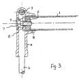
- Fig. 3 is a sectional view of one end of the completed assembly, in which the moulded cap 4 for the loop portion 3, omitted for clarity in Fig. 2, is shown.
- the end of the handle tube 1 is inserted in the sleeve portion 5.
- the sleeve portion is not essential, a simple aperture in the cap would suffice.
- a hole provided in the cap 4 opposite the handle end is filled by a trim insert 9 for improved aesthetics.
- Figs. 4 and 5 illustrate a second embodiment of the invention, in which the same reference numerals denote elements which are the same as or equivalent to those of the first embodiment.
- the sleeve portion 5 of the moulded cap 4 has a more complicated structure.
- an internal annular wall 20 defines with the outer sleeve 5 a circular groove 21 in which the end of the handle tube 1 is seated.
- the tube 1 is again secured to the loop portion 3 by means of a bolt or screw 7 which passes through a hole in the metal pressing 8 into an insert in the form of a bush 6 pushed into the end of the tube 1.
- the bush 6 can be held in place by crimping the handle tube.
- the end of tube 1 does not directly contact the pressing 8, being prevented from doing so by the base of the groove 21 in the cap 4.
- the handle may be prevented from rotation by providing a tight-fit for the tube end in the groove 21, but, preferably, an additional component serves to prevent rotation.
- the additional component is a washer member 16 having two tabs 17 which extend toward the end of the handle tube.
- the washer member 16 is located on the pressing 8 which, for this purpose, is T-shaped.
- the "horizontal" top bar 18 of the T bridges the limbs 10, 11 of the loop 3, whereas the “vertical” bar 19 extends to the bend of the loop.
- the washer member is located on the vertical bar 19, which incorporates the hole 15 for the fixing screw 7.
- Two slots (not shown) provided in the internal wall of the cap 4 enable the washer tabs 17 to be pushed through into the groove 21. As shown in Fig. 5, within the groove 21 the tabs 17 engage corresponding cut-outs 13 formed in the end of the tube 1, thus preventing rotation of the handle.
- the moulded cap 4 may have the same structure as in the first embodiment, i.e. without the circular groove.
- the end of the handle may contact the fixing plate 8 or be spaced therefrom according to the length of the washer tab 17 and the depth of the cut-out 13. Again, the engagement of the washer with the fixing plate and of the handle tube cut-outs with the washer tabs prevents rotation of the handle.
- Figs. 6 and 7 illustrate a third embodiment of the invention, in which the same reference numerals denote elements which are the same as or equivalent to those of the first and second embodiments.
- this embodiment differs from the previous ones in the structure of the support.
- a pair of separate wire portions 22 which extend substantially parallel to one another and lie in a common plane.
- a metal plate 8 is rigidly fixed between the free ends of the wire portions 22.
- the wire portions 22 may be circumferentially flattened at their free ends so as to seat the plate 8, as shown in the sectional view of Fig. 6(a).
- the plate 8 has a portion which projects beyond the ends of the wire portions 22 and receives the end of the handle tube 1.
- this embodiment is basically the same as the first embodiment.
- the end of the handle tube 1 is secured to the plate 8 by means of insert 6 and fixing bolt of screw 7.
- the end of the handle tube 1 has a pair of cut-outs, the projecting portion of the plate 8 having corresponding reduced width sections (see Fig. 7) which engage the cut-outs to prevent rotation of the handle.
- the support comprises wire, it could alternatively comprise tube.
Landscapes
- Engineering & Computer Science (AREA)
- Chemical & Material Sciences (AREA)
- Combustion & Propulsion (AREA)
- Transportation (AREA)
- Mechanical Engineering (AREA)
- Handcart (AREA)
- Steering Devices For Bicycles And Motorcycles (AREA)
Applications Claiming Priority (2)
| Application Number | Priority Date | Filing Date | Title |
|---|---|---|---|
| GB929220685A GB9220685D0 (en) | 1992-10-01 | 1992-10-01 | Handlebar assembly for a trolley |
| GB9220685 | 1992-10-01 |
Publications (2)
| Publication Number | Publication Date |
|---|---|
| EP0591006A1 true EP0591006A1 (de) | 1994-04-06 |
| EP0591006B1 EP0591006B1 (de) | 1997-05-14 |
Family
ID=10722803
Family Applications (1)
| Application Number | Title | Priority Date | Filing Date |
|---|---|---|---|
| EP19930307836 Expired - Lifetime EP0591006B1 (de) | 1992-10-01 | 1993-10-01 | Lenkstange für Handwagen |
Country Status (4)
| Country | Link |
|---|---|
| EP (1) | EP0591006B1 (de) |
| DE (1) | DE69310661T2 (de) |
| ES (1) | ES2101239T3 (de) |
| GB (2) | GB9220685D0 (de) |
Cited By (4)
| Publication number | Priority date | Publication date | Assignee | Title |
|---|---|---|---|---|
| EP0798194A1 (de) * | 1996-03-27 | 1997-10-01 | Clares Merchandise Handling Equipment Limited | Montagevorrichtung für Schiebegriffe und Transportvorrichtung versehen mit solcher Vorrichtung |
| FR2758512A1 (fr) * | 1997-01-21 | 1998-07-24 | Caddie Atel Reunis | Brancard de manoeuvre pour chariot comportant deux montants et une poignee de prehension et dispositif de fixation d'une poignee sur montants pour un tel brancard |
| WO2005025964A1 (de) * | 2003-09-13 | 2005-03-24 | Wanzl Metallwarenfabrik Gmbh | Von hand bewegbarer transportwagen |
| WO2021148157A1 (de) | 2020-01-22 | 2021-07-29 | Wanzl GmbH & Co. KGaA | Klemmelement und transportwagen |
Families Citing this family (6)
| Publication number | Priority date | Publication date | Assignee | Title |
|---|---|---|---|---|
| US5494306A (en) * | 1995-03-27 | 1996-02-27 | Unr Industries, Inc. | Shopping cart with adjustable holder for cups |
| AU718496B2 (en) * | 1995-08-21 | 2000-04-13 | A.F.M. Engineering Pty Ltd | Improved shopping trolley construction |
| US6065764A (en) * | 1998-08-28 | 2000-05-23 | Moseley; Christine M. | Sanitary cover for a shopping cart handle |
| DE102009007135B4 (de) | 2009-02-02 | 2015-05-21 | Wanzl Metallwarenfabrik Gmbh | Stapelbarer Transportwagen |
| USD936326S1 (en) | 2020-04-28 | 2021-11-16 | George Tyler Currier, III | Protective interface device |
| US11207771B2 (en) | 2020-03-17 | 2021-12-28 | George Tyler Currier, III | Protective interface device with complementary case, stand and satchel |
Citations (3)
| Publication number | Priority date | Publication date | Assignee | Title |
|---|---|---|---|---|
| DE2050264A1 (de) * | 1969-10-17 | 1971-04-29 | Ateliers Reunis S A, Schiltigheim, Bas Rhm (Frankreich) | Vorrichtung zum Befestigen eines rohr formigen Stuckes am oberen Ende eines Bo gens aus einem Metallrohr od dgl |
| EP0351232A2 (de) * | 1988-07-15 | 1990-01-17 | Buko Limited | Montagevorrichtung für Handgriffe oder Lenkstangen von Handwagen |
| CA1274263A (en) * | 1986-04-01 | 1990-09-18 | Antoine Trubiano | Shopping cart handle attachment |
Family Cites Families (3)
| Publication number | Priority date | Publication date | Assignee | Title |
|---|---|---|---|---|
| GB221979A (en) * | 1923-10-27 | 1924-09-25 | Thomas James Stevens | Improvements relating to perambulators, push-chairs and the like |
| GB691595A (en) * | 1949-11-16 | 1953-05-20 | Marmet Ltd | Improvements relating to prams and like vehicles |
| FR2417426A1 (fr) * | 1978-02-16 | 1979-09-14 | Reunis Sa Ateliers | Brancard de manoeuvre pour chariots de transport ou manutention |
-
1992
- 1992-10-01 GB GB929220685A patent/GB9220685D0/en active Pending
-
1993
- 1993-10-01 ES ES93307836T patent/ES2101239T3/es not_active Expired - Lifetime
- 1993-10-01 DE DE1993610661 patent/DE69310661T2/de not_active Expired - Fee Related
- 1993-10-01 GB GB9320248A patent/GB2271094B/en not_active Expired - Fee Related
- 1993-10-01 EP EP19930307836 patent/EP0591006B1/de not_active Expired - Lifetime
Patent Citations (3)
| Publication number | Priority date | Publication date | Assignee | Title |
|---|---|---|---|---|
| DE2050264A1 (de) * | 1969-10-17 | 1971-04-29 | Ateliers Reunis S A, Schiltigheim, Bas Rhm (Frankreich) | Vorrichtung zum Befestigen eines rohr formigen Stuckes am oberen Ende eines Bo gens aus einem Metallrohr od dgl |
| CA1274263A (en) * | 1986-04-01 | 1990-09-18 | Antoine Trubiano | Shopping cart handle attachment |
| EP0351232A2 (de) * | 1988-07-15 | 1990-01-17 | Buko Limited | Montagevorrichtung für Handgriffe oder Lenkstangen von Handwagen |
Cited By (5)
| Publication number | Priority date | Publication date | Assignee | Title |
|---|---|---|---|---|
| EP0798194A1 (de) * | 1996-03-27 | 1997-10-01 | Clares Merchandise Handling Equipment Limited | Montagevorrichtung für Schiebegriffe und Transportvorrichtung versehen mit solcher Vorrichtung |
| FR2746758A1 (fr) * | 1996-03-27 | 1997-10-03 | Clares Merch Hand Equip Ltd | Dispositif de montage de barre de manoeuvre, et appareil de manutention ou de transport correspondant |
| FR2758512A1 (fr) * | 1997-01-21 | 1998-07-24 | Caddie Atel Reunis | Brancard de manoeuvre pour chariot comportant deux montants et une poignee de prehension et dispositif de fixation d'une poignee sur montants pour un tel brancard |
| WO2005025964A1 (de) * | 2003-09-13 | 2005-03-24 | Wanzl Metallwarenfabrik Gmbh | Von hand bewegbarer transportwagen |
| WO2021148157A1 (de) | 2020-01-22 | 2021-07-29 | Wanzl GmbH & Co. KGaA | Klemmelement und transportwagen |
Also Published As
| Publication number | Publication date |
|---|---|
| GB9320248D0 (en) | 1993-11-17 |
| EP0591006B1 (de) | 1997-05-14 |
| GB2271094A (en) | 1994-04-06 |
| ES2101239T3 (es) | 1997-07-01 |
| GB9220685D0 (en) | 1992-11-11 |
| DE69310661T2 (de) | 1998-01-02 |
| DE69310661D1 (de) | 1997-06-19 |
| GB2271094B (en) | 1995-09-20 |
Similar Documents
| Publication | Publication Date | Title |
|---|---|---|
| EP0359406B1 (de) | Rückenlehnenbefestigung | |
| EP0591006B1 (de) | Lenkstange für Handwagen | |
| JP3859592B2 (ja) | ギヤシフト組立品 | |
| JPH05305887A (ja) | 自転車用水筒ケージ | |
| GB2271143A (en) | Fixing device for sheet member | |
| US4834404A (en) | Shopping cart having an infant carrier and an infant carrier therefor | |
| US5647519A (en) | Crutch beverage holder | |
| EP1197425B1 (de) | Wiederaufladbare Batterie für Scheinwerfer und Befestigungsstruktur dafür | |
| US5397088A (en) | Vehicular sun visor holding bracket | |
| EP0646514B1 (de) | Schutzbügel für Kinderwagen | |
| US6641456B2 (en) | Independent wheel arrangement for toy vehicle | |
| JPS60185686A (ja) | 自転車への備品の固定のための装置 | |
| JPH0757207B2 (ja) | 座席構造枠組 | |
| JPH08256874A (ja) | 自動車用シートのシートバック | |
| JPH08230737A (ja) | 二輪車用の荷物かご固定構造 | |
| US4528974A (en) | Protective guard for combustion appliance | |
| EP0351232A2 (de) | Montagevorrichtung für Handgriffe oder Lenkstangen von Handwagen | |
| FR2726517B1 (fr) | Siege de vehicule automobile dont le dossier comporte un moyen d'adaptation pour une utilisation par un enfant | |
| JPH0349556Y2 (de) | ||
| KR930003629B1 (ko) | 쇼핑카트 | |
| JPH07197725A (ja) | 家具用蝶番 | |
| JPH0515234Y2 (de) | ||
| JP2605154Y2 (ja) | シートのクッション構造 | |
| JPH1134709A (ja) | 車輌用リヤシート | |
| JPS6344292Y2 (de) |
Legal Events
| Date | Code | Title | Description |
|---|---|---|---|
| PUAI | Public reference made under article 153(3) epc to a published international application that has entered the european phase |
Free format text: ORIGINAL CODE: 0009012 |
|
| AK | Designated contracting states |
Kind code of ref document: A1 Designated state(s): DE ES FR GB IT NL |
|
| RAP1 | Party data changed (applicant data changed or rights of an application transferred) |
Owner name: CLARES MERCHANDISE HANDLING EQUIPMENT LIMITED |
|
| 17P | Request for examination filed |
Effective date: 19940727 |
|
| 17Q | First examination report despatched |
Effective date: 19950425 |
|
| GRAG | Despatch of communication of intention to grant |
Free format text: ORIGINAL CODE: EPIDOS AGRA |
|
| GRAH | Despatch of communication of intention to grant a patent |
Free format text: ORIGINAL CODE: EPIDOS IGRA |
|
| RBV | Designated contracting states (corrected) |
Designated state(s): DE ES FR IT NL |
|
| GRAH | Despatch of communication of intention to grant a patent |
Free format text: ORIGINAL CODE: EPIDOS IGRA |
|
| GRAA | (expected) grant |
Free format text: ORIGINAL CODE: 0009210 |
|
| AK | Designated contracting states |
Kind code of ref document: B1 Designated state(s): DE ES FR IT NL |
|
| ITF | It: translation for a ep patent filed | ||
| REF | Corresponds to: |
Ref document number: 69310661 Country of ref document: DE Date of ref document: 19970619 |
|
| REG | Reference to a national code |
Ref country code: ES Ref legal event code: FG2A Ref document number: 2101239 Country of ref document: ES Kind code of ref document: T3 |
|
| ET | Fr: translation filed | ||
| PGFP | Annual fee paid to national office [announced via postgrant information from national office to epo] |
Ref country code: ES Payment date: 19971017 Year of fee payment: 5 |
|
| PGFP | Annual fee paid to national office [announced via postgrant information from national office to epo] |
Ref country code: NL Payment date: 19971029 Year of fee payment: 5 |
|
| PLBE | No opposition filed within time limit |
Free format text: ORIGINAL CODE: 0009261 |
|
| 26N | No opposition filed | ||
| PG25 | Lapsed in a contracting state [announced via postgrant information from national office to epo] |
Ref country code: ES Free format text: LAPSE BECAUSE OF NON-PAYMENT OF DUE FEES Effective date: 19981002 |
|
| PG25 | Lapsed in a contracting state [announced via postgrant information from national office to epo] |
Ref country code: NL Free format text: LAPSE BECAUSE OF NON-PAYMENT OF DUE FEES Effective date: 19990501 |
|
| NLV4 | Nl: lapsed or anulled due to non-payment of the annual fee |
Effective date: 19990501 |
|
| PG25 | Lapsed in a contracting state [announced via postgrant information from national office to epo] |
Ref country code: FR Free format text: LAPSE BECAUSE OF NON-PAYMENT OF DUE FEES Effective date: 20010629 |
|
| REG | Reference to a national code |
Ref country code: FR Ref legal event code: ST |
|
| REG | Reference to a national code |
Ref country code: ES Ref legal event code: FD2A Effective date: 19991113 |
|
| REG | Reference to a national code |
Ref country code: FR Ref legal event code: D3 |
|
| PG25 | Lapsed in a contracting state [announced via postgrant information from national office to epo] |
Ref country code: IT Free format text: LAPSE BECAUSE OF NON-PAYMENT OF DUE FEES;WARNING: LAPSES OF ITALIAN PATENTS WITH EFFECTIVE DATE BEFORE 2007 MAY HAVE OCCURRED AT ANY TIME BEFORE 2007. THE CORRECT EFFECTIVE DATE MAY BE DIFFERENT FROM THE ONE RECORDED. Effective date: 20051001 |
|
| PGFP | Annual fee paid to national office [announced via postgrant information from national office to epo] |
Ref country code: DE Payment date: 20061130 Year of fee payment: 14 |
|
| PGFP | Annual fee paid to national office [announced via postgrant information from national office to epo] |
Ref country code: FR Payment date: 20061208 Year of fee payment: 14 |
|
| PG25 | Lapsed in a contracting state [announced via postgrant information from national office to epo] |
Ref country code: DE Free format text: LAPSE BECAUSE OF NON-PAYMENT OF DUE FEES Effective date: 20080501 |
|
| REG | Reference to a national code |
Ref country code: FR Ref legal event code: ST Effective date: 20080630 |