EP0591090A2 - Behälter mit innerer Hülle aus polymerem Material - Google Patents
Behälter mit innerer Hülle aus polymerem Material Download PDFInfo
- Publication number
- EP0591090A2 EP0591090A2 EP93600015A EP93600015A EP0591090A2 EP 0591090 A2 EP0591090 A2 EP 0591090A2 EP 93600015 A EP93600015 A EP 93600015A EP 93600015 A EP93600015 A EP 93600015A EP 0591090 A2 EP0591090 A2 EP 0591090A2
- Authority
- EP
- European Patent Office
- Prior art keywords
- jacket
- tank
- polymer material
- tanks
- internal
- Prior art date
- Legal status (The legal status is an assumption and is not a legal conclusion. Google has not performed a legal analysis and makes no representation as to the accuracy of the status listed.)
- Granted
Links
Images


Classifications
-
- B—PERFORMING OPERATIONS; TRANSPORTING
- B65—CONVEYING; PACKING; STORING; HANDLING THIN OR FILAMENTARY MATERIAL
- B65D—CONTAINERS FOR STORAGE OR TRANSPORT OF ARTICLES OR MATERIALS, e.g. BAGS, BARRELS, BOTTLES, BOXES, CANS, CARTONS, CRATES, DRUMS, JARS, TANKS, HOPPERS, FORWARDING CONTAINERS; ACCESSORIES, CLOSURES, OR FITTINGS THEREFOR; PACKAGING ELEMENTS; PACKAGES
- B65D81/00—Containers, packaging elements, or packages, for contents presenting particular transport or storage problems, or adapted to be used for non-packaging purposes after removal of contents
- B65D81/38—Containers, packaging elements, or packages, for contents presenting particular transport or storage problems, or adapted to be used for non-packaging purposes after removal of contents with thermal insulation
- B65D81/3802—Containers, packaging elements, or packages, for contents presenting particular transport or storage problems, or adapted to be used for non-packaging purposes after removal of contents with thermal insulation rigid container in the form of a barrel or vat
- B65D81/3811—Containers, packaging elements, or packages, for contents presenting particular transport or storage problems, or adapted to be used for non-packaging purposes after removal of contents with thermal insulation rigid container in the form of a barrel or vat formed of different materials, e.g. laminated or foam filling between walls
-
- B—PERFORMING OPERATIONS; TRANSPORTING
- B65—CONVEYING; PACKING; STORING; HANDLING THIN OR FILAMENTARY MATERIAL
- B65D—CONTAINERS FOR STORAGE OR TRANSPORT OF ARTICLES OR MATERIALS, e.g. BAGS, BARRELS, BOTTLES, BOXES, CANS, CARTONS, CRATES, DRUMS, JARS, TANKS, HOPPERS, FORWARDING CONTAINERS; ACCESSORIES, CLOSURES, OR FITTINGS THEREFOR; PACKAGING ELEMENTS; PACKAGES
- B65D90/00—Component parts, details or accessories for large containers
- B65D90/02—Wall construction
- B65D90/04—Linings
Definitions
- the invention has as a basic idea the construction of tanks with inner lining from appropriate polymer material, in the form of a jacket, which has a shape similar to that of the corresponding tank, for the purpose of corrosion or other kind of protection of the inner side of the tanks.
- the tanks are used for storage or heating or other treatment (relevant uses) of liquids of any nature, with applications in e.g. storage water heaters, solar domestic hot water systems, etc.
- a production method of the previously mentioned product is described next, where the pre-constructed internal jacket from the polymer material is enclosed by the metallic parts of the tank, where these parts are either welded together or assembled with screws or by any other method.
- a description of a production method is included where the internal jacket from polymer material is shaped directly inside the tank.
- the invention concerns tanks with internal jacket (lining) made out of polymer material.
- the invention also concerns relevant production methods for the parts of the final product as well as the product itself.
- Raw materials utilized for the construction of the internal jackets, which are used as inner lining of tanks, are various polymer materials, with low, medium or high density and with low, medium or high molecular weight.
- the selection of the raw material depends on the desirable properties or characteristics of the lining (anticorrosion or antitoxic, etc.) as well as on the cost.
- polyethylene, polypropylene, etc. are mentioned.
- the description of the invention will be based on storage water heaters (i.e. stationary appliance for heating water in a tank intended for long term or temporary storage of the heated water and provided with a device or devices to control and/or limit the water temperature), with internal jacket (lining) made out of high density, high molecular weight polyethylene. Similar procedures, with no important variations, are applied to all types of tanks as well as to various raw materials used to construct the internal jackets.
- storage water heaters i.e. stationary appliance for heating water in a tank intended for long term or temporary storage of the heated water and provided with a device or devices to control and/or limit the water temperature
- internal jacket made out of high density, high molecular weight polyethylene.
- the storage water heaters include electric water heaters, solar water heaters, and tanks with heat exchangers which operate in cooperation with the heating system of a house, etc.
- the corrosion protection of storage water heaters mainly concerns the protection of the internal surface of the corresponding tanks which is exposed to the corrosive action and/or electrolytic phenomena, due to the liquids contained in the tanks, leading to tank failure.
- a new type of product is created in accordance with this invention, which satisfies the needs for corrosion protection, as a combination of an internal jacket (lining) made of polymer material which is resistant to corrosion and a metallic tank (usually made out of steel or other material) in direct contact with the internal jacket and which can sustain the hydraulic pressure inside the tank.
- an internal jacket made of polymer material which is resistant to corrosion
- a metallic tank usually made out of steel or other material
- Water or other corrosive liquid which is stored or circulates inside the storage water heater and which is manufactured in accordance with this invention, does not come in contact with the internal metallic surfaces of the heater because of the existence of the walls of the internal jacket made of polymer material which is resistant to the corrosion. This way, any corrosion problems or electrolytical phenomena on the inner surface of the metallic tank are eliminated and perfect corrosion protection is achieved.
- the internal jacket from polymer material which is used for the lining of the tank is constructed in such shape so that complete contact is achieved with the inner surface of the tank and in this way the walls of the jacket are fully supported and no stresses are developed on them other than a compression due to hydraulic pressure.
- the tank (usually made of steel or other material) being in direct contact with the internal jacket provides the necessary strength and rigidity to sustain the hydraylic pressure inside the tank, without being under the influence of the corrosive action of the liquid inside, which can destroy it.
- the internal jacket made of polymer material and used for the lining of storage water heaters can be constructed at any desirable thickness and in this way corrosion protection is achieved for long time period.
- the internal jacket form polymer material which is used for the inner lining of tanks can be constructed by various methods such as:
- the cost and the technical characteristics of the material for the internal jacket are such that they allow any desirable thickness of the lining (indicative thickness of 2-3mm is mentioned), providing this way reliability and durability to the jacket at the required level and so reducing the danger caused by marginal designs which are obligatory when more expensive materials and methods are utilized for the purpose of corrosion protection.
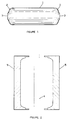
- Figure 1 shows in general terms a storage water heater (solar, electric, etc. or a tank for storage of hot water or other liquids) which will be protected against corrosion by the use of an internal jacket from polymer material in accordance with the invention. It is easy to see the cylidrical part (1) of the tank, the two ends or heads (2) and the two openings (3).
- a storage water heater solar, electric, etc. or a tank for storage of hot water or other liquids
- Figures 2 and 3 present schematically and in general terms the basic principle of forming the jackets from polymer material by blow moulding. Specifically in Figure 2, the tube (4) from polymer material with the proper diameter, temperature and thickness (known as parison), is shown in front of the two halves of the mould (5), which are apart (mould is open).
- Figure 3 shows the two parts of the mould in the closed position where they have entrapped the tube where compressed air is blown inside the tube from the upper opening of the mould (8).
- the tube is shown just as it starts to be inflated by the compressed air.
- the tube is expanded against the cavity of the mould, it takes the shape of the mould and it becomes firm due to the fact that the walls of the mould are cooled.
- the cooling water enters the mould from points (7) and leaves it from points (6).
- the cooling system is shown only schematically while in reality there are more inlet and exit points of the cooling water.
- Figure 4 illustrates schematically the production of an internal jacket by the method of rotational moulding.
- the mould is rotated by a proper device about two perpendicular axes simultaneously and has the desirable shape and the appropriate temperature (it is heated).
- the raw material is inserted into the mould from the opening (11) throught the nozzle (10).
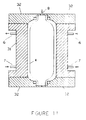
- FIG. 5 shows an internal jacket from polymer material (12), which is inside the cylindrical part (13) of the metallic tank to which it will be the inner lining. Shown also in place is the right head (14) of the metallic tank which however is not welded to the cylindrical part. The left head (15) is ready to be placed in its position. With a proper device, the three parts of the metallic tank and the jacket are held together so that circular welding can take place at points (16). There is always the possibility of adding a specific material between the jacket and the walls of the tank, in solid or liquid form for the purpose of improving the mechanical or thermal characteristics of the storage water heaters.
- Figure 6 shows the way that the ends of the head (17) and the cylindrical part (13) are shaped at the points of the circular welding (16).
- This shape provides the capability for a complete fit along the axis of the tank, between the two heads and the jacket, while at the same time the effect of the generated heat, due to circular welding at points (16), on the internal jacket from polymer material, is considerably reduced.
- Additional thermal protection of the internal jacket is achieved by the use of thermal shields, made from strips which are either metallic (copper, aluminium, steel, etc) or insulating or other materials, which are inserted between the jacket and the metallic tank at the points of circular welding.
- thermal shields made from strips which are either metallic (copper, aluminium, steel, etc) or insulating or other materials, which are inserted between the jacket and the metallic tank at the points of circular welding.
- the ends of the heads (17) and those of the cylindrical part (13) are placed opposite one another at points (16) where the circular welding is conducted. In this case however there is a need for a stronger shield system.
- FIG 7 shows the metallic tank (20) after the circular weldings have been completed, and with the jacket (12) from polymer material inside it.
- One end of the jacket (21) has been cut in the necessary length and with proper thermal and mechanical processes this end is bent to a right angle as it is seen on the opposite side of the jacket (22). This bending is conducted in both ends of the jacket.
- Figure 8 shows in a schematic way the method used for the bending of the end (25) of the jacket (12) from polymer material.
- the sources of heat (24) which heat the end of the jacket (25) until its temperature reaches a desirable level (similar heating takes place simultaneously at the other end of the jacket).
- a special tool which consists of parts (26) and (27), is moved towards the tank (similar tool exists at the opposite side of the jacket where this tool also moves towards the tank) and as soon as the part (26) is inside the tank through the opening (23), it extends by a special mechanism, it takes the shape (28), which is shown clearly at the right side of this figure, and it supports the jacket on the tank, at the location of the opening (23).
- the part (28) While the part (28) remains in this position, the part (27) starts moving towards the tank (this action takes place simultaneously at both sides of the tank), where initially the end of the jacket (already heated), is bent into a right angle [the jacket is being supported at the same time at the other side of the opening (23) by the extended part (28)] and next, the ends of the jacket and of the tank are compressed between parts (27) and (28) with simultaneous cooling of the end of the jacket through part (27) [the entrance of the cooling water is shown schematically at point (29) and the exit at point (30)] in order that the end of the jacket becomes firm in the new position.
- the part (28) returns to its initial shape and the whole system of the specially designed moving tool [i.e. parts (26) and (27)] retreats from the tank.
- Figures 9, 10 and 11 generally explain the basic principle of forming the jacket by blow moulding of a tube from polymer material (4) directly into the tank (20), where the jacket will remain as an internal lining (of the tank).
- the parts of the mould (32) have also been moved towards the tank and compressed air is fed into the tube through the opening (8).
- the tube (4) is shown just as it starts to be inflated by the compressed air.
- the tube is expanded against the internal walls of tank and partially of the mould [part (32)], it takes the corresponding shape and it becomes firm due to the fact that the walls of the tank are cooled at their external side.
- the cooling water enters the mould from points (7) and comes out from points (6).
- the cooling system is shown only in a schematic form. After the jacket is formed, the mould opens, first parts (32) and then parts (31), and the tank with the jacket inside is removed from the mould. The ends of the jacket are formed next by applying the process which is shown in figure 8.
Landscapes
- Engineering & Computer Science (AREA)
- Mechanical Engineering (AREA)
- Filling Or Discharging Of Gas Storage Vessels (AREA)
- Laminated Bodies (AREA)
- Table Devices Or Equipment (AREA)
- Lining Or Joining Of Plastics Or The Like (AREA)
Applications Claiming Priority (2)
| Application Number | Priority Date | Filing Date | Title |
|---|---|---|---|
| GR92010392 | 1992-09-15 | ||
| GR92100392 | 1992-09-15 |
Publications (3)
| Publication Number | Publication Date |
|---|---|
| EP0591090A2 true EP0591090A2 (de) | 1994-04-06 |
| EP0591090A3 EP0591090A3 (en) | 1994-05-11 |
| EP0591090B1 EP0591090B1 (de) | 1996-10-09 |
Family
ID=10941175
Family Applications (1)
| Application Number | Title | Priority Date | Filing Date |
|---|---|---|---|
| EP93600015A Expired - Lifetime EP0591090B1 (de) | 1992-09-15 | 1993-07-29 | Behälter mit innerer Hülle aus polymerem Material |
Country Status (6)
| Country | Link |
|---|---|
| EP (1) | EP0591090B1 (de) |
| AT (1) | ATE143895T1 (de) |
| DE (1) | DE69305305T2 (de) |
| DK (1) | DK0591090T3 (de) |
| ES (1) | ES2095024T3 (de) |
| GR (1) | GR1001347B (de) |
Cited By (2)
| Publication number | Priority date | Publication date | Assignee | Title |
|---|---|---|---|---|
| WO1996010155A1 (en) * | 1994-09-29 | 1996-04-04 | Christos Fyrogenis | Metallic tanks with inner liner for the storage of liquids under pressure |
| US20190241359A1 (en) * | 2018-02-05 | 2019-08-08 | Intermodal Liner, Llc | Liner for tank container |
Family Cites Families (1)
| Publication number | Priority date | Publication date | Assignee | Title |
|---|---|---|---|---|
| US4595112A (en) * | 1984-07-12 | 1986-06-17 | Greif Bros. Corporation | Thermal container |
-
1992
- 1992-09-15 GR GR920100392A patent/GR1001347B/el unknown
-
1993
- 1993-07-29 AT AT93600015T patent/ATE143895T1/de not_active IP Right Cessation
- 1993-07-29 DK DK93600015.7T patent/DK0591090T3/da active
- 1993-07-29 ES ES93600015T patent/ES2095024T3/es not_active Expired - Lifetime
- 1993-07-29 DE DE69305305T patent/DE69305305T2/de not_active Expired - Fee Related
- 1993-07-29 EP EP93600015A patent/EP0591090B1/de not_active Expired - Lifetime
Cited By (3)
| Publication number | Priority date | Publication date | Assignee | Title |
|---|---|---|---|---|
| WO1996010155A1 (en) * | 1994-09-29 | 1996-04-04 | Christos Fyrogenis | Metallic tanks with inner liner for the storage of liquids under pressure |
| US20190241359A1 (en) * | 2018-02-05 | 2019-08-08 | Intermodal Liner, Llc | Liner for tank container |
| US10807794B2 (en) * | 2018-02-05 | 2020-10-20 | Composite Containers, Llc | Liner for tank container |
Also Published As
| Publication number | Publication date |
|---|---|
| DE69305305D1 (de) | 1996-11-14 |
| EP0591090B1 (de) | 1996-10-09 |
| EP0591090A3 (en) | 1994-05-11 |
| GR1001347B (el) | 1993-10-29 |
| ATE143895T1 (de) | 1996-10-15 |
| ES2095024T3 (es) | 1997-02-01 |
| DK0591090T3 (da) | 1997-03-17 |
| DE69305305T2 (de) | 1997-03-20 |
Similar Documents
| Publication | Publication Date | Title |
|---|---|---|
| US3359351A (en) | Method of applying insulation coating for pipe | |
| NO784369L (no) | Isolasjonskappe for roer. | |
| NL8003271A (nl) | Bekleed metalen reservoir met hitteschild en werkwijze voor vervaardiging daarvan. | |
| EP0192274B1 (de) | Verfahren zur Herstellung zusammengesetzter Rohre | |
| US3941087A (en) | Resin coated steel pipe and the process and equipment for its production | |
| EP0591090A2 (de) | Behälter mit innerer Hülle aus polymerem Material | |
| US5522523A (en) | Water heater having flexible liner and method for making the same | |
| WO2009077966A2 (en) | Heater tank | |
| US4368217A (en) | Process for providing a polytetrafluoroethylene coating on the walls of a metal body | |
| CN113895124A (zh) | 一种抗渗透氟塑料制品、制备方法及抗渗透防腐容器设备 | |
| CA2542572C (en) | Condensing gas fired water heater | |
| CN109386692A (zh) | 硬质聚氨酯模具发泡与聚乙烯缠绕结合保温管及制造方法 | |
| EP0134363A2 (de) | Behälter zur Verwendung als Druckgefäss in einem Heisswassersystem | |
| DK164041B (da) | Metal-plast-kompositbeholder og fremgangmaade til sammenfoejning af plader ved svejsning kant mod kant med henblik paa fremstilling af en saadan beholder | |
| CN1159062A (zh) | 核反应堆压力容器及管道的金属保温层 | |
| US4398879A (en) | On-site fabricating of plastic pipe fittings | |
| WO1996040450A1 (en) | In-line coating and curing a continuously moving welded tube with an organic polymer | |
| EP2040511B1 (de) | Polytetrafluorethylen-Heizelement für ein Reaktor und Verfahren zu dessen Herstellung | |
| KR970005459A (ko) | 내화성형불의 유도 가열 방법 및 장치 | |
| IE86663B1 (en) | Hot water storage cylinder | |
| CN109806529B (zh) | 一种快速自动灭火管 | |
| EP0337357B1 (de) | Behälterkonstruktion und Verfahren zur Herstellung | |
| WO1996010155A1 (en) | Metallic tanks with inner liner for the storage of liquids under pressure | |
| JP3689160B2 (ja) | 断熱構造部材の製造方法およびそれにより得られる部材 | |
| CA2180354A1 (en) | A Method and Apparatus for Producing a Bell Joint |
Legal Events
| Date | Code | Title | Description |
|---|---|---|---|
| PUAI | Public reference made under article 153(3) epc to a published international application that has entered the european phase |
Free format text: ORIGINAL CODE: 0009012 |
|
| PUAL | Search report despatched |
Free format text: ORIGINAL CODE: 0009013 |
|
| AK | Designated contracting states |
Kind code of ref document: A2 Designated state(s): AT BE CH DE DK ES FR GB IE IT LI LU MC NL PT SE |
|
| AK | Designated contracting states |
Kind code of ref document: A3 Designated state(s): AT BE CH DE DK ES FR GB IE IT LI LU MC NL PT SE |
|
| 17P | Request for examination filed |
Effective date: 19950118 |
|
| 17Q | First examination report despatched |
Effective date: 19951013 |
|
| GRAG | Despatch of communication of intention to grant |
Free format text: ORIGINAL CODE: EPIDOS AGRA |
|
| GRAH | Despatch of communication of intention to grant a patent |
Free format text: ORIGINAL CODE: EPIDOS IGRA |
|
| GRAH | Despatch of communication of intention to grant a patent |
Free format text: ORIGINAL CODE: EPIDOS IGRA |
|
| GRAA | (expected) grant |
Free format text: ORIGINAL CODE: 0009210 |
|
| AK | Designated contracting states |
Kind code of ref document: B1 Designated state(s): AT BE CH DE DK ES FR GB IE IT LI LU MC NL PT SE |
|
| REF | Corresponds to: |
Ref document number: 143895 Country of ref document: AT Date of ref document: 19961015 Kind code of ref document: T |
|
| REF | Corresponds to: |
Ref document number: 69305305 Country of ref document: DE Date of ref document: 19961114 |
|
| REG | Reference to a national code |
Ref country code: IE Ref legal event code: FG4D Free format text: 70157 |
|
| ET | Fr: translation filed | ||
| ITF | It: translation for a ep patent filed | ||
| REG | Reference to a national code |
Ref country code: CH Ref legal event code: NV Representative=s name: BUGNION S.A. |
|
| REG | Reference to a national code |
Ref country code: ES Ref legal event code: FG2A Ref document number: 2095024 Country of ref document: ES Kind code of ref document: T3 |
|
| REG | Reference to a national code |
Ref country code: DK Ref legal event code: T3 |
|
| REG | Reference to a national code |
Ref country code: PT Ref legal event code: SC4A Free format text: AVAILABILITY OF NATIONAL TRANSLATION Effective date: 19961210 |
|
| PLBE | No opposition filed within time limit |
Free format text: ORIGINAL CODE: 0009261 |
|
| STAA | Information on the status of an ep patent application or granted ep patent |
Free format text: STATUS: NO OPPOSITION FILED WITHIN TIME LIMIT |
|
| 26N | No opposition filed | ||
| REG | Reference to a national code |
Ref country code: GB Ref legal event code: IF02 |
|
| PGFP | Annual fee paid to national office [announced via postgrant information from national office to epo] |
Ref country code: IE Payment date: 20021129 Year of fee payment: 10 |
|
| PGFP | Annual fee paid to national office [announced via postgrant information from national office to epo] |
Ref country code: PT Payment date: 20030624 Year of fee payment: 11 |
|
| PGFP | Annual fee paid to national office [announced via postgrant information from national office to epo] |
Ref country code: CH Payment date: 20030627 Year of fee payment: 11 |
|
| PGFP | Annual fee paid to national office [announced via postgrant information from national office to epo] |
Ref country code: DK Payment date: 20030702 Year of fee payment: 11 |
|
| PGFP | Annual fee paid to national office [announced via postgrant information from national office to epo] |
Ref country code: SE Payment date: 20030714 Year of fee payment: 11 |
|
| PGFP | Annual fee paid to national office [announced via postgrant information from national office to epo] |
Ref country code: GB Payment date: 20030722 Year of fee payment: 11 |
|
| PGFP | Annual fee paid to national office [announced via postgrant information from national office to epo] |
Ref country code: MC Payment date: 20030724 Year of fee payment: 11 |
|
| PGFP | Annual fee paid to national office [announced via postgrant information from national office to epo] |
Ref country code: FR Payment date: 20030725 Year of fee payment: 11 Ref country code: DE Payment date: 20030725 Year of fee payment: 11 Ref country code: AT Payment date: 20030725 Year of fee payment: 11 |
|
| PG25 | Lapsed in a contracting state [announced via postgrant information from national office to epo] |
Ref country code: IE Free format text: LAPSE BECAUSE OF NON-PAYMENT OF DUE FEES Effective date: 20030729 |
|
| PGFP | Annual fee paid to national office [announced via postgrant information from national office to epo] |
Ref country code: NL Payment date: 20030731 Year of fee payment: 11 Ref country code: ES Payment date: 20030731 Year of fee payment: 11 Ref country code: BE Payment date: 20030731 Year of fee payment: 11 |
|
| PGFP | Annual fee paid to national office [announced via postgrant information from national office to epo] |
Ref country code: LU Payment date: 20030804 Year of fee payment: 11 |
|
| PG25 | Lapsed in a contracting state [announced via postgrant information from national office to epo] |
Ref country code: LU Free format text: LAPSE BECAUSE OF NON-PAYMENT OF DUE FEES Effective date: 20040729 Ref country code: GB Free format text: LAPSE BECAUSE OF NON-PAYMENT OF DUE FEES Effective date: 20040729 Ref country code: AT Free format text: LAPSE BECAUSE OF NON-PAYMENT OF DUE FEES Effective date: 20040729 |
|
| PG25 | Lapsed in a contracting state [announced via postgrant information from national office to epo] |
Ref country code: SE Free format text: LAPSE BECAUSE OF NON-PAYMENT OF DUE FEES Effective date: 20040730 Ref country code: ES Free format text: LAPSE BECAUSE OF NON-PAYMENT OF DUE FEES Effective date: 20040730 |
|
| PG25 | Lapsed in a contracting state [announced via postgrant information from national office to epo] |
Ref country code: MC Free format text: LAPSE BECAUSE OF NON-PAYMENT OF DUE FEES Effective date: 20040731 Ref country code: LI Free format text: LAPSE BECAUSE OF NON-PAYMENT OF DUE FEES Effective date: 20040731 Ref country code: CH Free format text: LAPSE BECAUSE OF NON-PAYMENT OF DUE FEES Effective date: 20040731 Ref country code: BE Free format text: LAPSE BECAUSE OF NON-PAYMENT OF DUE FEES Effective date: 20040731 |
|
| PG25 | Lapsed in a contracting state [announced via postgrant information from national office to epo] |
Ref country code: DK Free format text: LAPSE BECAUSE OF NON-PAYMENT OF DUE FEES Effective date: 20040802 |
|
| BERE | Be: lapsed |
Owner name: *FYROGENIS VASILIOS Effective date: 20040731 Owner name: *FYROGENIS CHRISTOS Effective date: 20040731 |
|
| PG25 | Lapsed in a contracting state [announced via postgrant information from national office to epo] |
Ref country code: PT Free format text: LAPSE BECAUSE OF NON-PAYMENT OF DUE FEES Effective date: 20050131 |
|
| PG25 | Lapsed in a contracting state [announced via postgrant information from national office to epo] |
Ref country code: NL Free format text: LAPSE BECAUSE OF NON-PAYMENT OF DUE FEES Effective date: 20050201 Ref country code: DE Free format text: LAPSE BECAUSE OF NON-PAYMENT OF DUE FEES Effective date: 20050201 |
|
| REG | Reference to a national code |
Ref country code: DK Ref legal event code: EBP |
|
| EUG | Se: european patent has lapsed | ||
| REG | Reference to a national code |
Ref country code: CH Ref legal event code: PL |
|
| GBPC | Gb: european patent ceased through non-payment of renewal fee |
Effective date: 20040729 |
|
| PG25 | Lapsed in a contracting state [announced via postgrant information from national office to epo] |
Ref country code: FR Free format text: LAPSE BECAUSE OF NON-PAYMENT OF DUE FEES Effective date: 20050331 |
|
| NLV4 | Nl: lapsed or anulled due to non-payment of the annual fee |
Effective date: 20050201 |
|
| REG | Reference to a national code |
Ref country code: FR Ref legal event code: ST Ref country code: PT Ref legal event code: MM4A Free format text: LAPSE DUE TO NON-PAYMENT OF FEES Effective date: 20050131 |
|
| PG25 | Lapsed in a contracting state [announced via postgrant information from national office to epo] |
Ref country code: IT Free format text: LAPSE BECAUSE OF NON-PAYMENT OF DUE FEES;WARNING: LAPSES OF ITALIAN PATENTS WITH EFFECTIVE DATE BEFORE 2007 MAY HAVE OCCURRED AT ANY TIME BEFORE 2007. THE CORRECT EFFECTIVE DATE MAY BE DIFFERENT FROM THE ONE RECORDED. Effective date: 20050729 |
|
| REG | Reference to a national code |
Ref country code: ES Ref legal event code: FD2A Effective date: 20040730 |
|
| REG | Reference to a national code |
Ref country code: IE Ref legal event code: MM4A |
|
| BERE | Be: lapsed |
Owner name: *FYROGENIS VASILIOS Effective date: 20040731 Owner name: *FYROGENIS CHRISTOS Effective date: 20040731 |