EP0591201B1 - Dispositif d'injection de carburant pour moteurs a combustion interne - Google Patents
Dispositif d'injection de carburant pour moteurs a combustion interne Download PDFInfo
- Publication number
- EP0591201B1 EP0591201B1 EP91917579A EP91917579A EP0591201B1 EP 0591201 B1 EP0591201 B1 EP 0591201B1 EP 91917579 A EP91917579 A EP 91917579A EP 91917579 A EP91917579 A EP 91917579A EP 0591201 B1 EP0591201 B1 EP 0591201B1
- Authority
- EP
- European Patent Office
- Prior art keywords
- piston
- valve
- fuel
- feed
- bore
- Prior art date
- Legal status (The legal status is an assumption and is not a legal conclusion. Google has not performed a legal analysis and makes no representation as to the accuracy of the status listed.)
- Expired - Lifetime
Links
- 239000000446 fuel Substances 0.000 title claims abstract description 110
- 238000002347 injection Methods 0.000 title claims description 81
- 239000007924 injection Substances 0.000 title claims description 81
- 238000002485 combustion reaction Methods 0.000 title claims description 11
- 230000001133 acceleration Effects 0.000 claims description 17
- 238000006073 displacement reaction Methods 0.000 claims description 8
- 239000012530 fluid Substances 0.000 claims description 8
- 239000002828 fuel tank Substances 0.000 claims description 6
- 239000007921 spray Substances 0.000 claims description 5
- 238000012546 transfer Methods 0.000 claims description 3
- 230000002093 peripheral effect Effects 0.000 claims 1
- 230000000903 blocking effect Effects 0.000 abstract description 3
- 238000006243 chemical reaction Methods 0.000 abstract 1
- 238000005381 potential energy Methods 0.000 abstract 1
- 238000000034 method Methods 0.000 description 15
- 230000008569 process Effects 0.000 description 15
- 230000008901 benefit Effects 0.000 description 6
- 238000004146 energy storage Methods 0.000 description 6
- 238000013461 design Methods 0.000 description 5
- 238000005507 spraying Methods 0.000 description 5
- 230000006835 compression Effects 0.000 description 4
- 238000007906 compression Methods 0.000 description 4
- 238000013016 damping Methods 0.000 description 3
- 230000010354 integration Effects 0.000 description 3
- 239000000463 material Substances 0.000 description 3
- 230000002411 adverse Effects 0.000 description 2
- 238000004891 communication Methods 0.000 description 2
- 230000005284 excitation Effects 0.000 description 2
- 239000007788 liquid Substances 0.000 description 2
- 238000012986 modification Methods 0.000 description 2
- 230000004048 modification Effects 0.000 description 2
- 230000009467 reduction Effects 0.000 description 2
- 230000001105 regulatory effect Effects 0.000 description 2
- 239000007787 solid Substances 0.000 description 2
- 230000007704 transition Effects 0.000 description 2
- 238000004804 winding Methods 0.000 description 2
- 238000000889 atomisation Methods 0.000 description 1
- 238000010276 construction Methods 0.000 description 1
- 230000001276 controlling effect Effects 0.000 description 1
- 230000003247 decreasing effect Effects 0.000 description 1
- 238000011161 development Methods 0.000 description 1
- 230000018109 developmental process Effects 0.000 description 1
- 239000002283 diesel fuel Substances 0.000 description 1
- 230000000694 effects Effects 0.000 description 1
- 230000005520 electrodynamics Effects 0.000 description 1
- 239000003502 gasoline Substances 0.000 description 1
- 230000003116 impacting effect Effects 0.000 description 1
- 230000001771 impaired effect Effects 0.000 description 1
- 230000001902 propagating effect Effects 0.000 description 1
- 230000000979 retarding effect Effects 0.000 description 1
- 230000035939 shock Effects 0.000 description 1
- 238000011144 upstream manufacturing Methods 0.000 description 1
Images




Classifications
-
- F—MECHANICAL ENGINEERING; LIGHTING; HEATING; WEAPONS; BLASTING
- F02—COMBUSTION ENGINES; HOT-GAS OR COMBUSTION-PRODUCT ENGINE PLANTS
- F02M—SUPPLYING COMBUSTION ENGINES IN GENERAL WITH COMBUSTIBLE MIXTURES OR CONSTITUENTS THEREOF
- F02M59/00—Pumps specially adapted for fuel-injection and not provided for in groups F02M39/00 -F02M57/00, e.g. rotary cylinder-block type of pumps
- F02M59/20—Varying fuel delivery in quantity or timing
- F02M59/36—Varying fuel delivery in quantity or timing by variably-timed valves controlling fuel passages to pumping elements or overflow passages
- F02M59/366—Valves being actuated electrically
-
- F—MECHANICAL ENGINEERING; LIGHTING; HEATING; WEAPONS; BLASTING
- F02—COMBUSTION ENGINES; HOT-GAS OR COMBUSTION-PRODUCT ENGINE PLANTS
- F02M—SUPPLYING COMBUSTION ENGINES IN GENERAL WITH COMBUSTIBLE MIXTURES OR CONSTITUENTS THEREOF
- F02M51/00—Fuel-injection apparatus characterised by being operated electrically
- F02M51/04—Pumps peculiar thereto
-
- F—MECHANICAL ENGINEERING; LIGHTING; HEATING; WEAPONS; BLASTING
- F02—COMBUSTION ENGINES; HOT-GAS OR COMBUSTION-PRODUCT ENGINE PLANTS
- F02M—SUPPLYING COMBUSTION ENGINES IN GENERAL WITH COMBUSTIBLE MIXTURES OR CONSTITUENTS THEREOF
- F02M55/00—Fuel-injection apparatus characterised by their fuel conduits or their venting means; Arrangements of conduits between fuel tank and pump F02M37/00
- F02M55/02—Conduits between injection pumps and injectors, e.g. conduits between pump and common-rail or conduits between common-rail and injectors
-
- F—MECHANICAL ENGINEERING; LIGHTING; HEATING; WEAPONS; BLASTING
- F02—COMBUSTION ENGINES; HOT-GAS OR COMBUSTION-PRODUCT ENGINE PLANTS
- F02M—SUPPLYING COMBUSTION ENGINES IN GENERAL WITH COMBUSTIBLE MIXTURES OR CONSTITUENTS THEREOF
- F02M55/00—Fuel-injection apparatus characterised by their fuel conduits or their venting means; Arrangements of conduits between fuel tank and pump F02M37/00
- F02M55/04—Means for damping vibrations or pressure fluctuations in injection pump inlets or outlets
-
- F—MECHANICAL ENGINEERING; LIGHTING; HEATING; WEAPONS; BLASTING
- F02—COMBUSTION ENGINES; HOT-GAS OR COMBUSTION-PRODUCT ENGINE PLANTS
- F02M—SUPPLYING COMBUSTION ENGINES IN GENERAL WITH COMBUSTIBLE MIXTURES OR CONSTITUENTS THEREOF
- F02M57/00—Fuel-injectors combined or associated with other devices
- F02M57/02—Injectors structurally combined with fuel-injection pumps
- F02M57/022—Injectors structurally combined with fuel-injection pumps characterised by the pump drive
- F02M57/027—Injectors structurally combined with fuel-injection pumps characterised by the pump drive electric
-
- F—MECHANICAL ENGINEERING; LIGHTING; HEATING; WEAPONS; BLASTING
- F02—COMBUSTION ENGINES; HOT-GAS OR COMBUSTION-PRODUCT ENGINE PLANTS
- F02M—SUPPLYING COMBUSTION ENGINES IN GENERAL WITH COMBUSTIBLE MIXTURES OR CONSTITUENTS THEREOF
- F02M59/00—Pumps specially adapted for fuel-injection and not provided for in groups F02M39/00 -F02M57/00, e.g. rotary cylinder-block type of pumps
- F02M59/20—Varying fuel delivery in quantity or timing
- F02M59/22—Varying quantity or timing by adjusting cylinder-head space
-
- F—MECHANICAL ENGINEERING; LIGHTING; HEATING; WEAPONS; BLASTING
- F02—COMBUSTION ENGINES; HOT-GAS OR COMBUSTION-PRODUCT ENGINE PLANTS
- F02M—SUPPLYING COMBUSTION ENGINES IN GENERAL WITH COMBUSTIBLE MIXTURES OR CONSTITUENTS THEREOF
- F02M59/00—Pumps specially adapted for fuel-injection and not provided for in groups F02M39/00 -F02M57/00, e.g. rotary cylinder-block type of pumps
- F02M59/44—Details, components parts, or accessories not provided for in, or of interest apart from, the apparatus of groups F02M59/02 - F02M59/42; Pumps having transducers, e.g. to measure displacement of pump rack or piston
- F02M59/46—Valves
- F02M59/466—Electrically operated valves, e.g. using electromagnetic or piezoelectric operating means
-
- F—MECHANICAL ENGINEERING; LIGHTING; HEATING; WEAPONS; BLASTING
- F02—COMBUSTION ENGINES; HOT-GAS OR COMBUSTION-PRODUCT ENGINE PLANTS
- F02M—SUPPLYING COMBUSTION ENGINES IN GENERAL WITH COMBUSTIBLE MIXTURES OR CONSTITUENTS THEREOF
- F02M63/00—Other fuel-injection apparatus having pertinent characteristics not provided for in groups F02M39/00 - F02M57/00 or F02M67/00; Details, component parts, or accessories of fuel-injection apparatus, not provided for in, or of interest apart from, the apparatus of groups F02M39/00 - F02M61/00 or F02M67/00; Combination of fuel pump with other devices, e.g. lubricating oil pump
- F02M63/06—Use of pressure wave generated by fuel inertia to open injection valves
-
- F—MECHANICAL ENGINEERING; LIGHTING; HEATING; WEAPONS; BLASTING
- F02—COMBUSTION ENGINES; HOT-GAS OR COMBUSTION-PRODUCT ENGINE PLANTS
- F02B—INTERNAL-COMBUSTION PISTON ENGINES; COMBUSTION ENGINES IN GENERAL
- F02B2275/00—Other engines, components or details, not provided for in other groups of this subclass
- F02B2275/14—Direct injection into combustion chamber
-
- Y—GENERAL TAGGING OF NEW TECHNOLOGICAL DEVELOPMENTS; GENERAL TAGGING OF CROSS-SECTIONAL TECHNOLOGIES SPANNING OVER SEVERAL SECTIONS OF THE IPC; TECHNICAL SUBJECTS COVERED BY FORMER USPC CROSS-REFERENCE ART COLLECTIONS [XRACs] AND DIGESTS
- Y02—TECHNOLOGIES OR APPLICATIONS FOR MITIGATION OR ADAPTATION AGAINST CLIMATE CHANGE
- Y02T—CLIMATE CHANGE MITIGATION TECHNOLOGIES RELATED TO TRANSPORTATION
- Y02T10/00—Road transport of goods or passengers
- Y02T10/10—Internal combustion engine [ICE] based vehicles
- Y02T10/12—Improving ICE efficiencies
Definitions
- the invention relates to a device for injecting fuel for internal combustion engines of the type specified in the preamble of claim 1.
- Fuel injection devices for internal combustion engines are widespread and have prevailed in practice in different designs, but which have various shortcomings.
- pumps For direct injection of diesel fuel or injection in the so-called prechamber process, pumps are used which have cam-operated plungers or pistons, the cams being arranged on a camshaft driven directly by the engine crankshaft. The quantity is adjusted via control edges incorporated in the pistons or plungers. Pumps of this type have a high operating power requirement over the entire crank path of the internal combustion engine or the diesel engine and are in particular not accessible to an electronic control.
- an injection device of the type mentioned at the beginning of an electronic control is basically accessible.
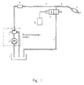
- the construction of such a known injection device will be described in more detail below with reference to FIG. 1 in connection with FIGS. 2 and 3, which shows typical pressure profiles of the pressure surge device via which fuel is supplied to the injection nozzle.
- a fuel pump 2 With a pressure of approximately 3 to 10 bar into a pipeline 5, in which a pressure regulator 3 and a damping device 4 are arranged.
- an electromagnetically operated shut-off valve 6 via which fuel accelerated by the pump 2 in the open state is returned to the reservoir 1.
- the size of the resulting pressure surge is approximately 20 to 80 bar, that is approximately 10 times the flow pressure generated by the pump 2 in the line 5, which is also called a flywheel line.
- the pressure surge thus created on the shut-off valve 6 is used to spray off the fuel accelerated in this way via an injection nozzle 10, which is connected via a pressure line 9 to the valve 6 and thus to the line 5.
- this known injection device can be controlled electronically, specifically by means of an electronic control unit 8 connected to the valve 6.
- the pressure surge generated when the shut-off valve 6 suddenly closes in the swing line 5 travels in the form of a pressure wave at the speed of sound through the lines 5, 7 and 9, the energy of the pressure wave in the lines 5 and 9 being available for spraying fuel through the nozzle 10 stands.
- the pressure wave propagating in the swing line 5 is reflected at the outlet of the pump 2 and moves back to the shut-off valve 6.
- the duration of the phase of this direct pressure surge corresponds to the duration of the pressure wave through the flywheel 5 and causes the pressure duration at the injection nozzle 10.
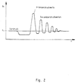
- a pressure surge remains in the flywheel 5, a residual pressure energy that runs back and forth in the flywheel. 2 shows a typical time course of the pressure surge in the flywheel line in the absence of the damping device 4 in line 5.
- This pressure course is characterized by a primary pressure wave of maximum energy and subsequent secondary pressure waves with increasing decreasing energy. In principle, all of these pressure waves can cause an injection. However, the consequence of these pressure waves limits the achievable working frequency of the system, which is why the secondary pressure waves are suppressed in favor of defined working conditions.
- the damping device 4 arranged in the flywheel 5 serves to suppress all secondary pressure waves. A corresponding pressure curve is shown in FIG. 3, it becoming clear that the secondary pressure waves are suppressed apart from a small residual ripple between successive primary pressure waves.
- the conventional injection device of the generic type described with reference to FIGS. 1 to 3 is characterized by electronic controllability, the characteristic of the injection pressure in particular being fundamentally independent of the speed of the internal combustion engine is. Due to the steep pressure rise and pressure drop in the pressure surge device, a quick opening and closing of the injection nozzle and thus a good fuel atomization process can be achieved.
- a disadvantage of the previous fuel injection device described above is that a pre-pressure supply is required which provides the energy required to accelerate the fuel-liquid column in the flywheel line and which operates continuously.
- This continuously working pre-pressure supply requires a corresponding effort for keeping the pressure constant.
- the amount of fuel delivered by the pump 2 is discharged via the pressure control valve 3, which is connected to the reservoir 1 via a return line.
- This pressure reduction leads to a loss of energy, and thus, in addition to an increase in the fuel temperature, to pressure changes at the injection valve 6, as a result of which the accuracy of the injection is impaired.
- the pressure regulating valve 3 always requires a minimum regulating quantity in order to be able to work stably, as a result of which a further loss of energy occurs.
- the pressure supply unit Since the volume flow requirement on the injection nozzle 10 depends on the engine speed and the amount to be sprayed off, the pressure supply unit must promote the volume flow for full-load operation even when idling, which means that relatively large amounts of fuel with corresponding energy loss for the entire system must be shut off via the pressure control valve 3.
- the injection device described above with a continuously operating pump is indeed suitable for injection into so-called intake manifold injection engines, but not for direct injection into the combustion chamber of gasoline engines, since a much higher pressure level is required for this purpose, which means that the pump is constantly required Performance reached unacceptable sizes and would also require the pump because of the high pressures, dimensions and weights to be processed, which are particularly portable in vehicle engines.
- a corresponding device is known for example from DE-PS 598 918.
- This known device is based on a heavy electromagnet which, when excited, presses a piston connected to the armature into a displacement space, as a result of which the fuel is injected into the combustion chamber of the internal combustion engine via a nozzle.
- a shut-off valve is closed immediately before the injection process, which then seals the displacement space from a fuel inlet.
- This known device has the serious disadvantage that the high pressure level required for direct injection requires the use of a very large electromagnet, as a result of which the entire device is space-consuming and very slow, so that it is less suitable for vehicle engines.
- this known injection device was therefore further developed with the aim of small designs.
- Corresponding injection devices are known from DD-PS 120 514 and DD-PS 213 472. These devices operate on the system of kinetic energy storage. For this purpose, it is provided to accelerate the armature of the electromagnet and thus the fuel-liquid column over a longer distance before the pressure is built up, which is required to spray the fuel through the nozzle.
- These known devices are also referred to as pump nozzle elements, which operate on the solid-state energy storage principle.
- the fuel delivery chamber penetrated by the delivery piston is provided in a first section with axially arranged grooves through which the fuel is able to flow out without any significant pressure build-up occurring in the subsequent second section of the delivery room, that has no fluid drainage grooves.
- the delivery piston is therefore braked by the incompressible fuel, as a result of which a pressure is built up in the fuel, by means of which the resistance of the injection valve is overcome, so that fuel is sprayed off.
- the disadvantage here is that when the delivery plunger is immersed in the closed section of the delivery cylinder, large pressure losses occur due to unfavorable gap conditions, namely a large gap width and a small gap length, which adversely affect the pressure build-up required for the spraying.
- a serious disadvantage of the two solid-state energy storage injection devices described above is that the fuel injection process can only be controlled to a limited extent, that is to say it can only be adapted to the engine requirements to a limited extent.
- a device for injecting fuel for internal combustion engines with an injection nozzle in which fuel is supplied by a pressure surge device, which has a fuel accelerating pump and a fuel retarding device, the actuation of which accelerates the kinetic energy Fuel is suddenly converted into a shock wave squirting off the fuel via the injection nozzle, the pump being an intermittent piston pump. The fuel is returned to the reservoir in an open fuel circulation system.
- the known device is not freely controllable. The open cycle requires too much energy.
- the object of the invention is to provide a device for injecting fuel for internal combustion engines of the type mentioned at the outset, with which fuel can be injected in a precisely controllable manner, with low, optimally used energy, very quickly and decoupled from engine processes.
- the fuel volume flow required for the injection for each injection process only as long as it is required in accordance with the engine operating conditions in accordance with the time and quantity requirements.
- the use of an intermittently operated fuel acceleration pump means that there is no need for a continuous supply of upstream pressure in accordance with the prior art, which benefits the energy balance of the injection device.
- the use of the energy is further optimized according to the invention by using a common control device for the acceleration pump and the electrically actuated deceleration device, for example in the form of an electromagnetically actuated shut-off valve.
- An electromagnetically operated piston pump is preferably used as the intermittently operating fuel acceleration pump.
- a diaphragm pump is also suitable for accelerating fuel within the pressure surge device.
- an electromagnetic pump drive an electrodynamic, a mechanical or a drive by means of piezo elements can also be provided.
- the invention is advantageously realized in that a closed injection system is provided in which the shut-off valve is connected to the suction chamber behind the delivery piston of the piston pump .
- the piston pump of the closed injection system preferably also comprises an electromagnetic or solenoid drive, so that the piston pump can be operated optimally together with the electromagnetic shut-off valve by a common electronic control device.
- a piston pump for the closed injection system which is structurally simple and easy to control, provides that the delivery piston is formed together with the armature of the electromagnet. Piston faces of identical size allow loss-free acceleration of the piston.
- a major advantage of the closed injection system is that only the quantity of fuel that has been sprayed off in the previous injection cycle has to be delivered to the acceleration pump from the fuel tank.
- the acceleration pump is therefore closed Injection system for fuel delivery from the reservoir to apply less energy, which benefits the energy balance of the overall system.
- the closed injection system makes better use of the pressure surge generated when the shut-off valve suddenly closes compared to the open injection system. 1, part of the pressure surge is uselessly discharged via the return line into the fuel tank, this part of the pressure surge is applied to the rear of the pump piston in the closed injection system according to the invention and thus onto the hosed one Transfer fuel. This measure also benefits the overall energy balance of the injection system, which is why a correspondingly smaller design can be chosen for the fuel acceleration pump.
- shut-off valve in a common housing allows a further drastic reduction in size, as well as a simplified structure of the single grill device, in particular if the shut-off valve is also constructed as a solenoid.
- a shut-off valve can be provided with a valve member controlled according to the Bernoulli effect, which is constructed purely mechanically and therefore does not require any external energy supply.
- the invention provides a Kraftstaff injection device based on the solid-state energy storage principle.
- the invention provides for the energy of the piston pump to be closed in a closed delivery chamber along the entire delivery stroke save, and to build up the pressure energy required for a spraying over the injection nozzle in that the flow of the displaced fuel is stopped abruptly by means of a shut-off valve.
- the shut-off valve is advantageously implemented with an electromagnetic drive, so that both the valve and the pump can be controlled in the required manner by a common electronic control circuit.
- a major advantage of the solid-state energy storage principle implemented according to the invention is that the energy storage process, that is to say the acceleration of the piston, can be controlled by the time period of the piston advance without a substantial increase in pressure. Due to the possibility of a variable piston stroke as well as the fact that after closing the shut-off valve in the fuel supply to the pump, the drive magnet for the pump can be switched on for different lengths and can be excited with different intensities during this time, the injection length and the course can be influence required depending on the respective engine condition. Any combination of the pre-delivery stroke and the subsequent displacement phase due to the energized shut-off valve magnet can be used to represent all pressure profiles required in individual cases.
- FIGS. 4 to 6 Embodiments of the fuel injection device according to the invention are shown in FIGS. 4 to 6, the same reference numerals being used for the same components.
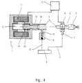
- the embodiment of a fuel injection device shown in FIG. 4 is based on a piston pump 1 with an electromagnetic drive for sucking fuel from a reservoir 2 and for accelerating the sucked fuel in a flywheel line 3, which is connected via a pressure line 4 to an injection nozzle 5. Furthermore, a shut-off valve 6 is arranged in a branch between the flywheel line 3 and the pressure line 4, which is designed as an electromagnetic valve and controls the fuel passage to a return line 7, which is connected to the shut-off valve 6 and opens into the reservoir 2.
- the shut-off valve 6 and the piston pump 1 are controlled via a common electronic control device 8, which is connected to the excitation coil of the solenoid valve 6 and to a coil of the drive electromagnet of the piston pump 1. Furthermore, a check valve 9 is arranged in a suction line 10, which connects the pump-side end of the flywheel 3 to the reservoir 2.
- the piston pump 1 comprises a magnet coil 11 with an armature 12 arranged in the coil passage, which is designed as a cylindrical body, for example as a solid body, is guided in a housing bore 13, which extends parallel to the central longitudinal axis of the ring coil 11, and by means of a compression spring 14 is biased in a rest position in which it bears in Fig. 4 at the left end of the housing bore 13 with its rear end wall.
- the other end wall of the armature 12 is acted upon by the spring 14, which is supported on the right end of the bore 13 on the housing wall of the pump 1.
- the spring-loaded end face of the armature 12 is fixedly connected to a piston rod 15, on the free end of which a piston 16, the delivery piston of the pump 1, is fastened, which is guided on the inner wall of the flywheel line 3 and is preferably sealed off from this wall.
- the piston rod 15 passes through a bore in the pump housing, the diameter of which is smaller than the diameter of the bore carrying the armature 12.
- the suction line 10 opens in front of the outer end face of the delivery piston 16 into the flywheel line 3.
- the check valve 9 in the delivery line 10 comprises, for example, a spring-loaded ball as a valve element, the ball and spring being arranged such that the spherical valve element in the check valve is raised when the delivery piston 16 for sucking fuel from the container 2 performs its suction stroke, i.e. when the piston 16 performs a stroke movement to the left in FIG. 4, which is the case when the magnet 11 is de-energized and the armature 12 into it Rest position is transferred by the spring 14.
- the other case namely during the delivery stroke of the piston 16, corresponding to a piston movement in FIG.
- the valve element of the check valve 10 is moved into its blocking position, so that the connection of the flywheel line 3 to the reservoir 2 is interrupted.
- the delivery stroke of the piston 16 accelerates the mass of the fuel located in the flywheel line 3 and transfers it into the return line 7 and via this into the container 2 during an opening period of the shut-off valve 6 predetermined by the control device 8. During this period there is primarily an acceleration of the fuel in the lines 3 and 7, and the fuel pressure is so low that the nozzle 5, for example hydraulically blocked in a manner known per se, assumes a blocking state in which no fuel can escape through the nozzle.
- the shut-off valve is also closed under the control of the device 8, as a result of which the kinetic energy of the in the lines 3 and 4 flowing fuel is suddenly converted into a pressure reservoir energy, the value of which is so high that the closing resistance of the nozzle 5 is overcome and fuel is sprayed off via the nozzle 5.
- While the injection device according to FIG. 4 represents an open system, a larger quantity of fuel is returned to the reservoir 2 via the line 7 into the container 2 during the acceleration stroke of the delivery piston 16 and is again sucked out of the container 2 during the suction stroke of the piston 16 5 shows an injection device according to the invention, in which the fuel is returned to the pump 1 in the circuit, wherein from the reservoir 2 during the suction stroke of the delivery piston 16, only the amount that was sprayed off through the nozzle 5 during the previous injection process is sucked in.
- Such a closed circuit requires less drive energy by the pump 1 compared to an open system, because a lower mass of fuel has to be moved, and a further decisive advantage is that the energy of the pressure surge is used for the spraying process, which occurs during the sudden closing of the shut-off valve is introduced into the downstream return line.
- FIG. 5 differs from that according to FIG. 4 by guiding the line 7 from the shut-off valve 6 to the rear of the delivery piston 16 (suction side) and in that, in addition to the check valve 9, a check valve 17 is provided, which is in series is switched to the check valve 9 and connects the front of the piston (delivery side) with the back of the piston (suction side).
- the check valve 17 is designed so that it assumes its closed position during the delivery stroke of the delivery piston 16, so that fluid compensation takes place between the front and rear sides of the piston.
- the suction line 10 of FIG. 4 is replaced in FIG. 5 by a line section 18 connecting the second check valve 17 to the swing line 3, the other end of the check valve 17 being connected via a line section 18 ′ to the line 7, one line section of which 19 branches off, which opens into the container 2 and in which the first check valve 9 is arranged, which corresponds in its function to the check valve 9 of FIG. 4.
- a pressure wave runs when the valve 6 closes not only between the latter and the front of the delivery piston, but also between the valve 6 via the line 7 and the rear of the delivery piston 16, this pressure component becoming the pressure component added in the flywheel in front of the piston, so that the entire pressure potential induced by the closing of the valve 6 in the fuel quantity is available for ejecting the fuel through the nozzle 5.
- the energy thus obtained in the injection system either allows the miniaturization of the pump 1 or, alternatively, a reduced current feed into the drive magnet of the pump 1.
- FIG. 6 A variant of the fuel injection device of FIG. 5 is shown in FIG. 6.
- This injector does not require the pressure accumulator 20 because the delivery piston is combined with the armature of the drive electromagnet, as a result of which both piston end faces are of the same size, so that the pressure on both sides of the piston is the same.
- the armature is made of the same material as the delivery piston, which is achieved in the illustrated embodiment in that the delivery piston 16 together with the piston rod 15 according to FIG. 5 is omitted.
- an opening 21 is formed in the pump housing on the back of the armature, to which the line 7 is connected.
- the operation of the device of Fig. 6 otherwise corresponds to that of Fig. 5, ie, the pressure energy introduced into the line 7 when the valve 6 is closed is transmitted to the back of the armature 12 acting as a delivery piston and thus in addition to the injection process Pressure surge provided, which has been generated in the flywheel 3 by closing the valve 6.
- Fig. 7 shows a modification of the injection device according to the invention according to Fig. 6.
- the modification consists in that the piston pump 1, the shut-off valve 6 and the second check valve 17 are housed as a structural unit in a common housing, the check valve 17 in the armature Delivery piston 12 is integrated.
- pump 1 and shut-off valve 6 are one behind the other on a common axis of the central longitudinal axis of the housing arranged.
- the shut-off valve 6, like the pump 1, is designed with an electromagnetic drive which comprises a coil 23, the current supply of which takes place via the common control device (not shown in FIG. 7) for the shut-off valve and the pump.
- the excitation winding 23 is ring-shaped like that of the pump and is held in a fitting recess of the housing 22 by means of a flange 24 which is fixedly connected to the housing 22.
- the winding 11 of the pump magnet is held in a fitting bore of the housing 22 by a flange 25.
- the flange 24 extends with a central portion into the coil 23 and comprises a central bore 26 which is connected to the flywheel 3 symbolized by arrows.
- the bore 26 is enlarged in its cross section, the shoulder formed by the extension forming a support for a spring 27, which serves as a return spring for the armature 28 of the shut-off valve electromagnet.
- This is received in a bore within the housing 22, which has a larger cross section than the bore 26 and its extension section.
- the armature 28 is designed as a hollow body and has on one side facing the bore 26 a recess which has approximately the same cross section as the enlargement of the bore 26.
- This recess is followed by a recess 29 of smaller cross section in the armature 28, the shoulder between the central bore 29 and the outer bore of larger cross-section forms a further support for the spring 27, which therefore presses the armature 28 to its right position in FIG. 7 when the electromagnet is not activated.
- the armature 28 forms the valve member of the shut-off valve 6.
- the armature 28 is on its front with a formed circumferential inclined surface, which comes into engagement when the shut-off valve electromagnet is de-energized, with a conical annular surface 30 formed in the housing 22 from appropriately formed, tapered annular surface , which can come into engagement with the valve seat 30, and in this case prevents leakage of fluid through the openings 31.
- valve member 28 is in its open position, in which its conical front side has moved away from the valve seat 30, so that fluid can pass through the openings 31 into the gap between the opposing inclined surfaces, and from this gap into a bore 32 which opens into the bore 13 for the armature / delivery piston 12 of the pump 1.
- the bore 13 is formed both in the housing 22 and in the central section of the flange 25, and the armature / piston 12 is biased into its rest position by the compression spring 14, for example in FIG. 5.
- This side of the bore for the piston 12 is connected, for example in the device of FIG. 5, to one end of the flywheel 3, the other end of which is connected to the bore 26 in the flange 24.
- the check valve 9 in the suction line to the reservoir 2 is connected to a bore 33 of the housing 22, which opens at the end into the bore 13 for the armature / piston 12, into which the connecting bore 32 also opens.
- the armature / piston 12 is hollow, that is to say has a central bore, and is designed as a valve element which fulfills the function of the second check valve 17 of the device according to FIGS. 5 and 6.
- the bore or the cavity within the armature / piston 12 has three sections of different cross-section, namely one of the connecting bore 32 opposite section of small diameter, approximately corresponding to the bore 32, a subsequent section of larger diameter in which a valve member 34 and a spring 35 biasing this member is arranged, and a subsequent section of larger diameter, which in the front face ( 7 on the right), a retaining ring 36 for the spring 35 being inserted in the shoulder area between this and the preceding section.
- the spring 35 is a compression spring that biases the valve member 34 against the valve seat, which is designed as a shoulder between the two first-mentioned bore sections of the armature / piston 12.
- the function of the injection device according to FIG. 7 essentially corresponds to that of the device of FIG. 6, to the description of which reference is hereby made.
- FIG. 8 shows an integration of the function of the shut-off valve 6 of the fuel injection device according to the invention in the armature 12 of the drive solenoid for the fuel acceleration pump 1, which armature is designed as a delivery piston, the arrangement shown roughly corresponding in function to the device from FIG. 6, and in FIG. 8, the second check valve 17 is not shown.
- the integration into the delivery piston makes control of the shut-off valve function by the control unit 8 superfluous, as is the case, for example, in the device of FIG. 6.
- the functional integration of the shut-off valve function in the function of the pump 1 simplifies the injection device, which results in a considerable amount of material. and saves space.
- the armature / piston 12 is designed as a cylindrical solid body and is mounted with the rear end in a bore 40 in the left part of the pump housing in FIG. 8, while a further bore 40a with the same diameter is formed in the right part of the pump housing and leads the front section during the delivery stroke of the piston 12.
- a central recess 41 is provided on the front end face of the armature / piston 12, the base surface of which forms one of the two bearings for the spring 14 for resetting the armature 12.
- the other bearing point for the spring 14 represents a shoulder between a delivery-side bore 43 and a subsequent narrower bore 44, to which the pump-side end of the flywheel line is connected.
- the spring 14 is, as in the preceding embodiments of the device according to the invention, a compression spring which prestresses the armature / piston 12 in its rest position, in which it rests with its rear end face on an annular surface which is formed in the transition area from the Bore 40 to a previous bore 45 of smaller diameter, which is in communication with the flywheel 3.
- the shoulder or the annular surface 46 in the transition area from the larger-diameter bore 40 to the smaller-diameter bore 43 serves as a stop surface for the annular front end wall of the armature / piston 12 and interacts with it in the sense of the function of the shut-off valve 6 of the embodiments of the invention described above.
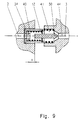
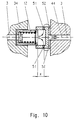
- FIGS. 9 to 11 Further variants of an integrated delivery piston / armature / shut-off valve are shown in FIGS. 9 to 11.
- a pressure surge is generated after covering a stroke of the armature / delivery piston 12 in the order of magnitude of x.
- the shut-off valve function according to FIG. 9 on an obstacle lying on the piston stroke route similar to that according to FIG. 8, is achieved by pushing the armature / piston, the realization of this function according to FIGS. 10 and 11 takes place by an abrupt interruption of the fuel acceleration by suddenly closing flow baffles in the form of narrow bores.
- the armature / piston 12 is guided in the embodiments according to FIGS. 9 to 11 in two bores 40 and 41 spaced apart in the axial direction, the rest of FIGS. 9 to 11 being the arrangement of FIG. 8, with the difference that the second check valve 17 is integrated into the armature / piston 12 designed as a hollow element, similar to the embodiment of the device according to the invention according to FIG. 7, as by the same reference numerals for the same components of the devices from FIG. 7 or 9 to 11 is clarified.
- FIG. 9 an embodiment is shown in which, after covering a stroke x the inner end face of the valve member 34 of the check valve 17 strikes a pin 50 which is arranged on the longitudinal central axis of the armature / piston bores 40 and 41. This impact causes the pressure surge described in FIG. 8.
- the fuel is accelerated by means of baffles in the form of narrow bores 51 and 52, which are formed in the region of the front end of the bore 41 in the conveying direction and are in communication with the housing bore 44 connected to the flywheel 10 as indicated by arrows, fuel contained in the interior of the armature / piston 12 flows via the bores 51 running transversely to the fuel delivery direction into bore 52 spaced in the delivery direction in the pump housing and from there into the bore 44 and finally into the bore 44 Swing line.
- this part of the piston closes the radial openings 51, as a result of which the acceleration of the fuel stops suddenly and a pressure surge is generated.
- the embodiment according to FIG. 11 differs from the variant according to FIG. 10 in that the flow baffles are designed in the form of openings 53 in a front end wall of the hollow armature / piston. After covering the stroke distance x, the front piston end wall with the radially outer openings 53 abuts the shoulder 46, as a result of which a flow of fluid from the inside of the piston into the bore 44 is suddenly interrupted, so that the kinetic energy of the flowing fuel is subjected to a pressure surge is converted, which leads to the ejection of fuel through the injection nozzle.
Landscapes
- Engineering & Computer Science (AREA)
- Chemical & Material Sciences (AREA)
- Combustion & Propulsion (AREA)
- Mechanical Engineering (AREA)
- General Engineering & Computer Science (AREA)
- Physics & Mathematics (AREA)
- Electromagnetism (AREA)
- Fuel-Injection Apparatus (AREA)
Claims (25)
- Dispositif d'injection de carburant pour moteurs à combustion interne, comportant une buse d'injection (5) qui reçoit le carburant au moyen d'un dispositif de pression impulsionnelle qui comprend une pompe à piston (1) pour accélérer le carburant, qui fonctionne par intermittence, et une soupape d'arrêt (6) qui retarde le flux du carburant et qui par son action transforme brusquement l'énergie cinétique du carburant accéléré en une onde de choc émettant un jet de carburant par la buse d'injection (5),
caractérisé en ce que la pompe à piston (1) est actionnée de manière électromagnétique, et en ce qu'il est prévu un dispositif de commande électronique (8) de la pompe (1) et un circuit de carburant, fermé pendant la course d'accélération et comportant la soupape d'arrêt (6) le circuit de carburant reliant l'espace d'aspiration derrière le piston d'alimentation (16) de la pompe (1) à l'espace de la conduite d'accélération devant le piston d'alimentation (16) de la pompe (1). - Dispositif selon la revendication 1, dans lequel la soupape d'arrêt (6) est connectée à une branche de la conduite d'accélération (3) reliant la pompe (1) à la buse d'injection (5), permettant, dans son état ouvert, un écoulement du carburant accéléré de la conduite d'accélération (3) vers la branche et engendrant, lors d'une fermeture brusque, l'onde de choc sous pression qui provoque l'éjection du carburant par la buse d'injection (5), l'espace de refoulement devant piston d'alimentation (16) de la pompe à piston (1) étant relié à la conduite d'accélération (3) et, par un clapet anti-retour (10), à un réservoir de carburant, de manière à ce que du carburant entre dans l'espace de refoulement, et ainsi dans la conduite d'accélération (3), lorsque le piston (16) est rappelé.
- Dispositif selon la revendication 1 et/ou 2,
caractérisé en ce que l'espace d'aspiration derrière le piston d'alimentation (16) est relié par un clapet anti-retour (17) à l'espace de refoulement devant piston (16) pour permettre un écoulement de carburant de l'espace d'aspiration vers l'espace de refoulement lorsque le piston (16) est rappelé. - Dispositif selon la revendication 3,
caractérisé en ce que la pompe à piston (1) comprend un entraînement magnétique dont l'armature (12) est reliée au piston d'alimentation (16) par une tige de piston (14). - Dispositif selon la revendication 4,
caractérisé en ce que la face arrière du piston d'alimentation est en outre reliée à un accumulateur de pression (20) pour compenser la différence de pression résultant de la différence de surface entre la face avant complète du piston et la face arrière du piston rendue annulaire par la connexion de la tige (14) du piston (16). - Dispositif selon la revendication 1 et/ou 2,
caractérisé en ce que l'entraînement de la pompe à piston (1) comprend un aimant dont l'armature (12) est en forme de piston d'alimentation avec deux faces frontales de dimensions identiques. - Dispositif selon l'une ou plusieurs des revendications 1 à 6,
caractérisé en ce que la pompe à piston (1) et la soupape d'arrêt (6) sont réalisées en une seule unité de construction. - Dispositif selon la revendication 7,
caractérisé en ce que la pompe à piston (1) et la soupape d'arrêt (6) sont disposées dans un boîtier commun (22) et consistent en des aimants immédiatement voisins dont les armatures (12 et 28) ont la forme de pistons ou de soupapes en forme de pistons. - Dispositif selon la revendication 8,
caractérisé par une disposition coaxiale du piston d'alimentation (12) et de l'organe de soupape en forme de piston (28). - Dispositif selon la revendication 9,
caractérisé en ce que la sortie de la soupape d'arrêt (6) est reliée par un canal de faible longueur (32) à l'espace d'aspiration situé en arrière de la pompe (1) dans lequel débouche un autre canal (33) qui peut être relié au clapet anti-retour relié au réservoir de carburant (2). - Dispositif selon l'une des revendications 8 à 10,
caractérisé en ce que l'organe de la soupape d'arrêt (6) est un piston creux (piston à alésage borgne) (28) rappelé par un ressort et présentant sur sa face avant des ouvertures de sortie du fluide (31) qui débouchent dans des faces obliques du piston (28) qui peuvent coopérer de manière étanche avec des surfaces obliques correspondantes (30) (siège de soupape) situées à l'extrémité antérieure d'un alésage recevant le piston (28). - Dispositif selon la revendication 11,
caractérisé en ce que les surfaces obliques sur l'extrémité avant du piston (28), ainsi que sur l'extrémité en regard de l'alésage du piston sont des surfaces tournantes coniques. - Dispositif selon l'une des revendications 8 à 12,
caractérisé en ce que le clapet anti-retour (34, 35) reliant l'espace d'aspiration situé en aval du piston d'alimentation (12) à l'espace de refoulement situé en amont du piston d'alimentation (12) est intégrée dans le piston d'alimentation (12). - Dispositif selon la revendication 13,
caractérisé en ce que le clapet anti-retour (34, 25) comprend un organe (34) qui est disposé dans un alésage passant ou alésage central du piston d'alimentation (12) et est poussé par un ressort (35) contre un siège de soupape situé à l'extrémité, postérieure dans le sens de circulation, de l'espace creux du piston d'alimentation. - Dispositif selon l'une ou plusieurs des revendications 1 à 14,
caractérisé en ce que la pompe à piston (1) est actionnée de manière électromagnétique, et que la soupape d'arrêt (6) est intégrée dans l'armature qui est réalisée sous la forme d'un piston d'alimentation (12) de la pompe à piston (1). - Dispositif selon la revendication 15,
caractérisé en ce que la course d'alimentation du piston (12) est délimitée par des moyens de butée (46), l'arrivée du piston d'alimentation (12) sur le moyen de butée (46) déclenchant l'onde de choc sous pression dans le carburant et mettant un terme à la circulation du carburant. - Dispositif selon la revendication 16,
caractérisé en ce que le moyen de butée (46) est un rétrécissement de l'alésage (40) recevant le piston d'alimentation (12) dans le boîtier de la pompe. - Dispositif selon la revendication 17,
caractérisé en ce que le rétrécissement est une surface annulaire (46) entre l'alésage (40) du piston d'alimentation et un alésage (43) de section transversale inférieure disposé en arrière dans la direction de circulation, la face, antérieure dans la direction de circulation, du piston (12) pouvant buter contre cette face annulaire. - Dispositif selon la revendication 18,
caractérisé en ce que le piston d'alimentation (12) présente un alésage passant central dans lequel est disposé le clapet anti-retour ayant la forme d'un organe de soupape (34), cet organe étant poussé contre un siège de soupape situé à l'extrémité, postérieure dans la direction de circulation, de l'alésage passant et rencontrant une butée (50) après avoir parcouru un trajet d'accélération prédéterminé du piston (12), en le freinant brusquement. - Dispositif selon la revendication 19,
caractérisé en ce que la butée est un ergot (50) qui s'étend le long de l'axe longitudinal central de l'alésage du piston d'alimentation. - Dispositif selon la revendication 15,
caractérisé en ce que, dans le trajet du piston d'alimentation (12), sont prévues des chicanes de circulation sous forme d'étranglements (51, 53) de la section du parcours qui sont fermées après une course prédéterminée du piston (12) en arrêtant ainsi le flux de carburant et en déclenchant l'onde de choc engendrant un jet de carburant par la buse d'injection. - Dispositif selon la revendication 21,
caractérisé en ce que les étranglements sont des alésages étroits (51, 52) entre un alésage qui reçoit le piston d'alimentation (12) et la conduite d'accélération (3) située en amont du piston (12), ces alésages étroits s'étendant radialement par rapport au piston (12) et pouvant être fermés par les surfaces d'enveloppe de ce dernier. - Dispositif selon la revendication 21,
caractérisé en ce que les étranglements ont la forme d'ouvertures pratiquées dans une paroi, antérieure dans la direction de circulation, du piston d'alimentation creux fermé à l'arrière par un clapet anti-retour (34), ces ouvertures étant fermées lorsque l'extrémité antérieure du piston entre dans un espace annulaire de l'alésage de piston dont le diamètre intérieur correspond sensiblement à celui de l'armature du piston. - Dispositif selon l'une des revendications 15 à 23,
caractérisé en ce que l'entrée et la sortie de la pompe de circulation (1) sont reliées entre elles par la conduite d'accélération (3), la buse d'injection (5) étant embranchée à la conduite d'accélération (3) dans la région de l'entrée de la pompe, tandis qu'un réservoir de carburant (2) est relié dans la région de la sortie de la pompe, au cours de la course d'aspiration de celle-ci, à la conduite d'accélération (3) au moyen d'un clapet anti-retour en vue de compenser le manque de carburant dans la conduite d'accélération (3) éjecté par la buse d'injection (5). - Dispositif selon l'une ou plusieurs des revendications 1 à 14,
caractérisé en ce que la soupape d'arrêt est un solénoïde dont l'armature (72) présente la forme d'un organe de soupape, est disposée dans un alésage du boîtier (73) et est munie d'un alésage traversant (76) qui est relié en permanence à une entrée de la soupape d'arrêt et à une sortie (80) de la soupape d'arrêt débouchant radialement dans l'alésage de boîtier (73), lorsque l'armature (72) se trouve à une extrémité de l'alésage de boîtier (73) lors de l'actionnement du solénoïde, et que, dans l'armature (72), sont prévues des fentes ou alésages radiaux (78) agencés avec un certain intervalle axial, qui relient l'alésage traversant de l'armature (76) à la surface périphérique de l'armature, qui, lorsqu'on actionne le solénoïde, sont isolées de la sortie de la soupape d'arrêt (80) par la paroi de l'alésage de boîtier (73) et qui entrent successivement en relation de transfert de carburant avec ladite sortie lorsque, sous l'action d'un ressort (74), l'armature (72) est déplacée vers l'autre extrémité de l'alésage de boîtier (73) quand le solénoïde est désexcité.
Priority Applications (1)
| Application Number | Priority Date | Filing Date | Title |
|---|---|---|---|
| EP95111191A EP0685646B1 (fr) | 1991-02-26 | 1991-10-07 | Dispositif d'injection de combustible pour moteurs à combustion interne |
Applications Claiming Priority (3)
| Application Number | Priority Date | Filing Date | Title |
|---|---|---|---|
| DE4106015A DE4106015A1 (de) | 1991-02-26 | 1991-02-26 | Druckstoss-kraftstoffeinspritzung fuer verbrennungsmotoren |
| DE4106015 | 1991-02-26 | ||
| PCT/EP1991/001902 WO1992014925A2 (fr) | 1991-02-26 | 1991-10-07 | Dispositif d'injection de carburant pour moteurs a combustion interne |
Related Child Applications (1)
| Application Number | Title | Priority Date | Filing Date |
|---|---|---|---|
| EP95111191.3 Division-Into | 1991-10-07 |
Publications (2)
| Publication Number | Publication Date |
|---|---|
| EP0591201A1 EP0591201A1 (fr) | 1994-04-13 |
| EP0591201B1 true EP0591201B1 (fr) | 1996-04-17 |
Family
ID=6425919
Family Applications (3)
| Application Number | Title | Priority Date | Filing Date |
|---|---|---|---|
| EP96108104A Expired - Lifetime EP0733799B1 (fr) | 1991-02-26 | 1991-10-07 | Dispositif d'injection de combustible pour moteurs à combustion interne |
| EP95111191A Expired - Lifetime EP0685646B1 (fr) | 1991-02-26 | 1991-10-07 | Dispositif d'injection de combustible pour moteurs à combustion interne |
| EP91917579A Expired - Lifetime EP0591201B1 (fr) | 1991-02-26 | 1991-10-07 | Dispositif d'injection de carburant pour moteurs a combustion interne |
Family Applications Before (2)
| Application Number | Title | Priority Date | Filing Date |
|---|---|---|---|
| EP96108104A Expired - Lifetime EP0733799B1 (fr) | 1991-02-26 | 1991-10-07 | Dispositif d'injection de combustible pour moteurs à combustion interne |
| EP95111191A Expired - Lifetime EP0685646B1 (fr) | 1991-02-26 | 1991-10-07 | Dispositif d'injection de combustible pour moteurs à combustion interne |
Country Status (9)
| Country | Link |
|---|---|
| US (1) | US5540206A (fr) |
| EP (3) | EP0733799B1 (fr) |
| JP (1) | JP2645264B2 (fr) |
| AT (3) | ATE184370T1 (fr) |
| AU (1) | AU653174B2 (fr) |
| CA (1) | CA2101755C (fr) |
| DE (4) | DE4106015A1 (fr) |
| ES (2) | ES2105823T3 (fr) |
| WO (1) | WO1992014925A2 (fr) |
Families Citing this family (37)
| Publication number | Priority date | Publication date | Assignee | Title |
|---|---|---|---|---|
| DE59303326D1 (de) * | 1992-03-04 | 1996-08-29 | Ficht Gmbh & Co Kg | Hubkolbenpumpe |
| DE4421145A1 (de) * | 1994-06-16 | 1995-12-21 | Ficht Gmbh | Ölbrenner |
| DE19515782A1 (de) | 1995-04-28 | 1996-10-31 | Ficht Gmbh | Kraftstoff-Einspritzvorrichtung für Brennkraftmaschinen |
| WO1996034195A1 (fr) * | 1995-04-28 | 1996-10-31 | Ficht Gmbh & Co. Kg | Injecteur de carburant pour moteurs a combustion interne |
| US5779454A (en) * | 1995-07-25 | 1998-07-14 | Ficht Gmbh & Co. Kg | Combined pressure surge fuel pump and nozzle assembly |
| DE19527550A1 (de) * | 1995-07-27 | 1997-01-30 | Ficht Gmbh | Verfahren zum Steuern des Zündzeitpunktes bei Brennkraftmaschinen |
| FR2751700B1 (fr) * | 1996-07-23 | 1998-10-30 | Peugeot Motocycles Sa | Electrovanne par exemple d'impact pour un systeme d'injection de carburant par effet de coup de belier dans un moteur de vehicule |
| FR2751701B1 (fr) * | 1996-07-23 | 1998-10-16 | Peugeot Motocycles Sa | Electrovanne notamment d'impact pour un systeme d'injection de carburant par effet de coup de belier dans un moteur de vehicule |
| US6161525A (en) * | 1996-08-30 | 2000-12-19 | Ficht Gmbh & Co. Kg | Liquid gas engine |
| DE19635248C2 (de) * | 1996-08-30 | 2001-05-23 | Ficht Gmbh & Co Kg | Flüssiggasmotor |
| DE19643886C2 (de) | 1996-10-30 | 2002-10-17 | Ficht Gmbh & Co Kg | Verfahren zum Betreiben einer Brennkraftmaschine |
| ATE231227T1 (de) * | 1997-03-12 | 2003-02-15 | Forsch Transferzentrum E V An | Verfahren zur kraftstoffeinspritzung in mehrzylinder-kraftmaschinen und vorrichtung zur durchführung des verfahrens |
| FR2761114B1 (fr) * | 1997-03-24 | 1999-06-25 | Peugeot Motocycles Sa | Dispositif d'amortissement d'ondes de pression de carburant reflechies dans un systeme d'injection de carburant |
| US6280867B1 (en) | 1997-12-05 | 2001-08-28 | Griff Consulting, Inc. | Apparatus for pumping a fluid in a fuel cell system |
| DE19844163C1 (de) * | 1998-09-25 | 2000-01-05 | Ficht Gmbh & Co Kg | Pumpverfahren und Pumpvorrichtung |
| DE19845441C2 (de) * | 1998-10-02 | 2003-01-16 | Ficht Gmbh & Co Kg | Verfahren zum elektronischen Trimmen einer Einspritzvorrichtung |
| SE9803894D0 (sv) * | 1998-11-12 | 1998-11-12 | Volvo Lastvagnar Ab | Rotary displacement pump |
| US6135073A (en) * | 1999-04-23 | 2000-10-24 | Caterpillar Inc. | Hydraulic check valve recuperation |
| DE19918423A1 (de) * | 1999-04-23 | 2000-10-26 | Denys F Hackert | Einspritzanlage für flüssige Medien |
| DE19919665A1 (de) * | 1999-04-29 | 2000-11-02 | Volkswagen Ag | Kraftstoffeinspritzvorrichtung |
| GB0005744D0 (en) * | 2000-03-10 | 2000-05-03 | Federal Mogul Ignition Uk Ltd | Fuel injector |
| US6966760B1 (en) * | 2000-03-17 | 2005-11-22 | Brp Us Inc. | Reciprocating fluid pump employing reversing polarity motor |
| JP4431268B2 (ja) * | 2000-11-17 | 2010-03-10 | 株式会社ミクニ | 電子制御燃料噴射装置 |
| US6568369B1 (en) | 2000-12-05 | 2003-05-27 | Caterpillar Inc | Common rail injector with separately controlled pilot and main injection |
| DE10145862A1 (de) * | 2001-09-18 | 2003-04-03 | Bosch Gmbh Robert | Verfahren zum Einspritzen von Kraftstoff sowie Ventil zum Steuern von Flüssigkeiten |
| ITTO20020453A1 (it) * | 2002-05-29 | 2003-12-01 | Vhit Spa | Circuito di iniezione di fluido ad alta pressione. |
| FR2841940B1 (fr) * | 2002-07-08 | 2004-09-10 | Renault Sa | Procede de commande d'injecteur d'un moteur a allumage par compression a rampe commune |
| DE10250882B4 (de) * | 2002-10-31 | 2004-12-30 | Webasto Thermosysteme Gmbh | Brennstoffzellensystem mit Reformer und vorgeschaltetem Gemischbildungssystem |
| DE10313419A1 (de) * | 2003-03-25 | 2004-11-04 | Robert Bosch Gmbh | Hubgesteuerter Common-Rail-Injektor mit Steller für Schwingungsanregung |
| JP2005036689A (ja) * | 2003-07-18 | 2005-02-10 | Keihin Corp | 燃料供給装置 |
| US7753657B2 (en) * | 2005-02-02 | 2010-07-13 | Brp Us Inc. | Method of controlling a pumping assembly |
| DE102006003484A1 (de) * | 2005-03-16 | 2006-09-21 | Robert Bosch Gmbh | Vorrichtung zum Einspritzen von Kraftstoff |
| US7677872B2 (en) * | 2007-09-07 | 2010-03-16 | Gm Global Technology Operations, Inc. | Low back-flow pulsation fuel injection pump |
| DE102009055042A1 (de) * | 2009-12-21 | 2011-06-22 | Robert Bosch GmbH, 70469 | Einspritzventil |
| US20130312706A1 (en) * | 2012-05-23 | 2013-11-28 | Christopher J. Salvador | Fuel system having flow-disruption reducer |
| DE102012011583A1 (de) * | 2012-06-13 | 2013-12-19 | Robert Bosch Gmbh | Vorrichtung und Verfahren zur Druckerzeugung für fließfähige Medien |
| CN108488016A (zh) * | 2018-05-07 | 2018-09-04 | 长沙燕通生物科技有限公司 | 可缓解柴油机启动冒黑烟的装置 |
Family Cites Families (24)
| Publication number | Priority date | Publication date | Assignee | Title |
|---|---|---|---|---|
| DE120514C (fr) * | ||||
| DE105653C (fr) * | ||||
| DE213472C (fr) * | ||||
| US1664607A (en) * | 1923-09-04 | 1928-04-03 | Louis O French | Fuel-injection system |
| US1664667A (en) * | 1927-02-04 | 1928-04-03 | Cleveland G Davis | Device for forcing ice-cream bricks from molds |
| GB397493A (en) * | 1932-02-18 | 1933-08-18 | William Douglas Marchant | Improvements in injection apparatus for fuel for internal combustion engines |
| US2666153A (en) * | 1950-12-22 | 1954-01-12 | Bendix Aviat Corp | Reciprocatory electric motor |
| JPS506043B1 (fr) * | 1969-05-19 | 1975-03-10 | ||
| DE2307435A1 (de) * | 1973-02-15 | 1974-08-22 | Bosch Gmbh Robert | Kraftstoffeinspritzeinrichtung fuer brennkraftmaschinen |
| DD105653A1 (fr) * | 1973-07-13 | 1974-05-05 | ||
| US3961612A (en) * | 1974-08-22 | 1976-06-08 | Diesel Kiki Kabushiki Kaisha | Fuel injection device for diesel engines |
| DD120514A1 (fr) * | 1975-06-09 | 1976-06-12 | ||
| DE2751457A1 (de) * | 1977-11-18 | 1979-05-23 | Bbc Brown Boveri & Cie | Selbstpumpendes elektromagnetisches einspritzventil |
| FR2449795B1 (fr) * | 1979-02-24 | 1986-11-28 | Huber Motorenbau Inst | Systeme d'injection pour moteur a combustion interne |
| ZA802506B (en) * | 1979-12-07 | 1981-05-27 | Lucas Industries Ltd | Fuel pumping apparatus |
| US4599983A (en) * | 1981-11-09 | 1986-07-15 | Kabushiki Kaisha Komatsu Seisakusho | Method and apparatus for injecting fuel for a diesel engine |
| DD213472B5 (de) * | 1983-02-04 | 1999-12-30 | Ficht Gmbh | Pumpe-Duese-System fuer Brennkraftmaschinen |
| US4838232A (en) * | 1984-08-14 | 1989-06-13 | Ail Corporation | Fuel delivery control system |
| EP0174261B1 (fr) * | 1984-08-14 | 1989-01-11 | Ail Corporation | Système de commande de l'alimentation |
| JPS61108865A (ja) * | 1984-10-31 | 1986-05-27 | Nippon Soken Inc | 圧電式燃料噴射装置 |
| JPS61171874A (ja) * | 1985-01-28 | 1986-08-02 | Nippon Denso Co Ltd | 2種燃料噴射装置 |
| SU1326761A1 (ru) * | 1986-03-17 | 1987-07-30 | Коломенский Филиал Всесоюзного Заочного Политехнического Института | Топливна система |
| GB8618839D0 (en) * | 1986-08-01 | 1986-09-10 | Lucas Ind Plc | Valve assembly |
| JP2568603B2 (ja) * | 1988-01-11 | 1997-01-08 | 日産自動車株式会社 | 燃料噴射装置 |
-
1991
- 1991-02-26 DE DE4106015A patent/DE4106015A1/de not_active Withdrawn
- 1991-10-07 US US08/107,835 patent/US5540206A/en not_active Expired - Lifetime
- 1991-10-07 AT AT96108104T patent/ATE184370T1/de not_active IP Right Cessation
- 1991-10-07 EP EP96108104A patent/EP0733799B1/fr not_active Expired - Lifetime
- 1991-10-07 DE DE59107701T patent/DE59107701D1/de not_active Expired - Fee Related
- 1991-10-07 ES ES95111191T patent/ES2105823T3/es not_active Expired - Lifetime
- 1991-10-07 ES ES91917579T patent/ES2088019T3/es not_active Expired - Lifetime
- 1991-10-07 AU AU86558/91A patent/AU653174B2/en not_active Ceased
- 1991-10-07 WO PCT/EP1991/001902 patent/WO1992014925A2/fr not_active Ceased
- 1991-10-07 AT AT91917579T patent/ATE136987T1/de active
- 1991-10-07 DE DE59108749T patent/DE59108749D1/de not_active Expired - Fee Related
- 1991-10-07 EP EP95111191A patent/EP0685646B1/fr not_active Expired - Lifetime
- 1991-10-07 AT AT95111191T patent/ATE154414T1/de not_active IP Right Cessation
- 1991-10-07 EP EP91917579A patent/EP0591201B1/fr not_active Expired - Lifetime
- 1991-10-07 DE DE59109152T patent/DE59109152D1/de not_active Expired - Fee Related
- 1991-10-07 CA CA002101755A patent/CA2101755C/fr not_active Expired - Fee Related
- 1991-10-07 JP JP3516220A patent/JP2645264B2/ja not_active Expired - Lifetime
Also Published As
| Publication number | Publication date |
|---|---|
| JP2645264B2 (ja) | 1997-08-25 |
| DE4106015A1 (de) | 1992-08-27 |
| EP0685646B1 (fr) | 1997-06-11 |
| WO1992014925A3 (fr) | 1993-02-04 |
| US5540206A (en) | 1996-07-30 |
| EP0733799A3 (fr) | 1996-12-04 |
| ATE136987T1 (de) | 1996-05-15 |
| CA2101755C (fr) | 1999-12-21 |
| CA2101755A1 (fr) | 1992-08-27 |
| EP0733799A2 (fr) | 1996-09-25 |
| DE59108749D1 (de) | 1997-07-17 |
| DE59109152D1 (de) | 1999-10-14 |
| ES2088019T3 (es) | 1996-08-01 |
| JPH06505067A (ja) | 1994-06-09 |
| EP0685646A1 (fr) | 1995-12-06 |
| ES2105823T3 (es) | 1997-10-16 |
| AU8655891A (en) | 1992-09-15 |
| EP0591201A1 (fr) | 1994-04-13 |
| AU653174B2 (en) | 1994-09-22 |
| EP0733799B1 (fr) | 1999-09-08 |
| ATE154414T1 (de) | 1997-06-15 |
| WO1992014925A2 (fr) | 1992-09-03 |
| DE59107701D1 (de) | 1996-05-23 |
| ATE184370T1 (de) | 1999-09-15 |
Similar Documents
| Publication | Publication Date | Title |
|---|---|---|
| EP0733799B1 (fr) | Dispositif d'injection de combustible pour moteurs à combustion interne | |
| EP0629265B1 (fr) | Dispositif d'injection de carburant fonctionnant selon le principe de l'accumulateur d'energie a solide pour moteurs a combustion interne | |
| DE68910658T2 (de) | Hochdruckpumpe mit veränderlichem Abfluss. | |
| DE3700687C2 (de) | Kraftstoffeinspritzanlage für eine Brennkraftmaschine | |
| DE102010063589A1 (de) | Konstantrestdruckventil | |
| DE4206817C2 (de) | Kraftstoff-Einspritzvorrichtung nach dem Festkörper-Energiespeicher-Prinzip für Brennkraftmaschinen | |
| DE19545162B4 (de) | Brennstoffeinspritzvorrichtung mit federvorgespanntem Steuerventil | |
| EP0432402B1 (fr) | Dispositif d'injection pour moteur à combustion interne à auto-allumage | |
| DE3523536A1 (de) | Elektrisch gesteuerte kraftstoffeinspritzpumpe fuer brennkraftmaschinen | |
| DE4421145A1 (de) | Ölbrenner | |
| EP0823019A1 (fr) | Systeme d'injection de carburant pour moteurs a combustion interne | |
| EP0204982B1 (fr) | Dispositif d'injection de combustible pour moteurs à combustion interne | |
| EP0467072B1 (fr) | Injecteur de carburant pour des moteurs à combustion interne à compressiond'air | |
| DE3743532A1 (de) | Kraftstoffeinspritzanlage fuer brennkraftmaschinen | |
| DE2343285A1 (de) | Elektromagnetisch betaetigbares kraftstoffeinspritzventil fuer brennkraftmaschinen | |
| DE19515774C2 (de) | Kraftstoff-Einspritzvorrichtung für Brennkraftmaschinen | |
| EP4080047B1 (fr) | Dispositif de pompe | |
| DE102006003484A1 (de) | Vorrichtung zum Einspritzen von Kraftstoff | |
| DE10155718C2 (de) | Einspritzsystem für Dieselmotoren | |
| EP0962649A1 (fr) | Dispositif d'injection de combustible | |
| AT408253B (de) | Einspritzdüse für eine brennkraftmaschine | |
| EP1214508A2 (fr) | Commande assistee par accumulateur d'energie des quantites d'injection dans des moteurs diesel importants | |
| EP1084343A1 (fr) | Dispositif de pompage | |
| EP0962648A1 (fr) | Dispositif d'injection de combustible | |
| EP2166217A1 (fr) | Moteur à combustion interne |
Legal Events
| Date | Code | Title | Description |
|---|---|---|---|
| PUAI | Public reference made under article 153(3) epc to a published international application that has entered the european phase |
Free format text: ORIGINAL CODE: 0009012 |
|
| 17P | Request for examination filed |
Effective date: 19930722 |
|
| AK | Designated contracting states |
Kind code of ref document: A1 Designated state(s): AT BE DE ES FR GB IT SE |
|
| 17Q | First examination report despatched |
Effective date: 19941212 |
|
| GRAA | (expected) grant |
Free format text: ORIGINAL CODE: 0009210 |
|
| AK | Designated contracting states |
Kind code of ref document: B1 Designated state(s): AT BE DE ES FR GB IT SE |
|
| REF | Corresponds to: |
Ref document number: 136987 Country of ref document: AT Date of ref document: 19960515 Kind code of ref document: T |
|
| XX | Miscellaneous (additional remarks) |
Free format text: TEILANMELDUNG 95111191.3 EINGEREICHT AM 17/07/95. |
|
| ET | Fr: translation filed | ||
| REF | Corresponds to: |
Ref document number: 59107701 Country of ref document: DE Date of ref document: 19960523 |
|
| GBT | Gb: translation of ep patent filed (gb section 77(6)(a)/1977) |
Effective date: 19960528 |
|
| REG | Reference to a national code |
Ref country code: ES Ref legal event code: BA2A Ref document number: 2088019 Country of ref document: ES Kind code of ref document: T3 |
|
| RAP2 | Party data changed (patent owner data changed or rights of a patent transferred) |
Owner name: FICHT GMBH & CO. KG |
|
| ITF | It: translation for a ep patent filed | ||
| REG | Reference to a national code |
Ref country code: ES Ref legal event code: FG2A Ref document number: 2088019 Country of ref document: ES Kind code of ref document: T3 |
|
| GRAH | Despatch of communication of intention to grant a patent |
Free format text: ORIGINAL CODE: EPIDOS IGRA |
|
| REG | Reference to a national code |
Ref country code: FR Ref legal event code: CD |
|
| BECA | Be: change of holder's address |
Free format text: 960417 *FICHT G.M.B.H. & CO. K.G.:SPANNLEITEBERG 1, D-85614 KICHSEEON |
|
| BECN | Be: change of holder's name |
Effective date: 19960417 |
|
| PLBE | No opposition filed within time limit |
Free format text: ORIGINAL CODE: 0009261 |
|
| STAA | Information on the status of an ep patent application or granted ep patent |
Free format text: STATUS: NO OPPOSITION FILED WITHIN TIME LIMIT |
|
| 26N | No opposition filed | ||
| PGFP | Annual fee paid to national office [announced via postgrant information from national office to epo] |
Ref country code: ES Payment date: 19981015 Year of fee payment: 8 |
|
| PGFP | Annual fee paid to national office [announced via postgrant information from national office to epo] |
Ref country code: AT Payment date: 19981022 Year of fee payment: 8 |
|
| PG25 | Lapsed in a contracting state [announced via postgrant information from national office to epo] |
Ref country code: AT Free format text: LAPSE BECAUSE OF NON-PAYMENT OF DUE FEES Effective date: 19991007 |
|
| PG25 | Lapsed in a contracting state [announced via postgrant information from national office to epo] |
Ref country code: ES Free format text: LAPSE BECAUSE OF NON-PAYMENT OF DUE FEES Effective date: 19991008 |
|
| REG | Reference to a national code |
Ref country code: GB Ref legal event code: IF02 |
|
| PGFP | Annual fee paid to national office [announced via postgrant information from national office to epo] |
Ref country code: BE Payment date: 20020927 Year of fee payment: 12 |
|
| PGFP | Annual fee paid to national office [announced via postgrant information from national office to epo] |
Ref country code: SE Payment date: 20021004 Year of fee payment: 12 |
|
| REG | Reference to a national code |
Ref country code: FR Ref legal event code: TP Ref country code: FR Ref legal event code: CD |
|
| PGFP | Annual fee paid to national office [announced via postgrant information from national office to epo] |
Ref country code: GB Payment date: 20031001 Year of fee payment: 13 |
|
| PGFP | Annual fee paid to national office [announced via postgrant information from national office to epo] |
Ref country code: FR Payment date: 20031003 Year of fee payment: 13 |
|
| PG25 | Lapsed in a contracting state [announced via postgrant information from national office to epo] |
Ref country code: SE Free format text: LAPSE BECAUSE OF NON-PAYMENT OF DUE FEES Effective date: 20031008 |
|
| PGFP | Annual fee paid to national office [announced via postgrant information from national office to epo] |
Ref country code: DE Payment date: 20031016 Year of fee payment: 13 |
|
| PG25 | Lapsed in a contracting state [announced via postgrant information from national office to epo] |
Ref country code: BE Free format text: LAPSE BECAUSE OF NON-PAYMENT OF DUE FEES Effective date: 20031031 |
|
| REG | Reference to a national code |
Ref country code: ES Ref legal event code: FD2A Effective date: 20001113 |
|
| BERE | Be: lapsed |
Owner name: *FICHT G.M.B.H. & CO. K.G. Effective date: 20031031 |
|
| EUG | Se: european patent has lapsed | ||
| PG25 | Lapsed in a contracting state [announced via postgrant information from national office to epo] |
Ref country code: GB Free format text: LAPSE BECAUSE OF NON-PAYMENT OF DUE FEES Effective date: 20041007 |
|
| PG25 | Lapsed in a contracting state [announced via postgrant information from national office to epo] |
Ref country code: DE Free format text: LAPSE BECAUSE OF NON-PAYMENT OF DUE FEES Effective date: 20050503 |
|
| GBPC | Gb: european patent ceased through non-payment of renewal fee |
Effective date: 20041007 |
|
| PG25 | Lapsed in a contracting state [announced via postgrant information from national office to epo] |
Ref country code: FR Free format text: LAPSE BECAUSE OF NON-PAYMENT OF DUE FEES Effective date: 20050630 |
|
| REG | Reference to a national code |
Ref country code: FR Ref legal event code: ST |
|
| PG25 | Lapsed in a contracting state [announced via postgrant information from national office to epo] |
Ref country code: IT Free format text: LAPSE BECAUSE OF NON-PAYMENT OF DUE FEES;WARNING: LAPSES OF ITALIAN PATENTS WITH EFFECTIVE DATE BEFORE 2007 MAY HAVE OCCURRED AT ANY TIME BEFORE 2007. THE CORRECT EFFECTIVE DATE MAY BE DIFFERENT FROM THE ONE RECORDED. Effective date: 20051007 |