EP0591225B1 - Dispositif servant a couper le bois de placage du contre-plaque - Google Patents
Dispositif servant a couper le bois de placage du contre-plaque Download PDFInfo
- Publication number
- EP0591225B1 EP0591225B1 EP92907313A EP92907313A EP0591225B1 EP 0591225 B1 EP0591225 B1 EP 0591225B1 EP 92907313 A EP92907313 A EP 92907313A EP 92907313 A EP92907313 A EP 92907313A EP 0591225 B1 EP0591225 B1 EP 0591225B1
- Authority
- EP
- European Patent Office
- Prior art keywords
- blade
- veneer
- cutting
- web
- shaft
- Prior art date
- Legal status (The legal status is an assumption and is not a legal conclusion. Google has not performed a legal analysis and makes no representation as to the accuracy of the status listed.)
- Expired - Lifetime
Links
Images
Classifications
-
- B—PERFORMING OPERATIONS; TRANSPORTING
- B26—HAND CUTTING TOOLS; CUTTING; SEVERING
- B26D—CUTTING; DETAILS COMMON TO MACHINES FOR PERFORATING, PUNCHING, CUTTING-OUT, STAMPING-OUT OR SEVERING
- B26D1/00—Cutting through work characterised by the nature or movement of the cutting member or particular materials not otherwise provided for; Apparatus or machines therefor; Cutting members therefor
- B26D1/56—Cutting through work characterised by the nature or movement of the cutting member or particular materials not otherwise provided for; Apparatus or machines therefor; Cutting members therefor involving a cutting member which travels with the work otherwise than in the direction of the cut, i.e. flying cutter
- B26D1/62—Cutting through work characterised by the nature or movement of the cutting member or particular materials not otherwise provided for; Apparatus or machines therefor; Cutting members therefor involving a cutting member which travels with the work otherwise than in the direction of the cut, i.e. flying cutter and is rotating about an axis parallel to the line of cut, e.g. mounted on a rotary cylinder
- B26D1/626—Cutting through work characterised by the nature or movement of the cutting member or particular materials not otherwise provided for; Apparatus or machines therefor; Cutting members therefor involving a cutting member which travels with the work otherwise than in the direction of the cut, i.e. flying cutter and is rotating about an axis parallel to the line of cut, e.g. mounted on a rotary cylinder for thin material, e.g. for sheets, strips or the like
-
- B—PERFORMING OPERATIONS; TRANSPORTING
- B26—HAND CUTTING TOOLS; CUTTING; SEVERING
- B26D—CUTTING; DETAILS COMMON TO MACHINES FOR PERFORATING, PUNCHING, CUTTING-OUT, STAMPING-OUT OR SEVERING
- B26D11/00—Combinations of several similar cutting apparatus
-
- B—PERFORMING OPERATIONS; TRANSPORTING
- B27—WORKING OR PRESERVING WOOD OR SIMILAR MATERIAL; NAILING OR STAPLING MACHINES IN GENERAL
- B27G—ACCESSORY MACHINES OR APPARATUS FOR WORKING WOOD OR SIMILAR MATERIALS; TOOLS FOR WORKING WOOD OR SIMILAR MATERIALS; SAFETY DEVICES FOR WOOD WORKING MACHINES OR TOOLS
- B27G1/00—Machines or devices for removing knots or other irregularities or for filling-up holes
-
- B—PERFORMING OPERATIONS; TRANSPORTING
- B27—WORKING OR PRESERVING WOOD OR SIMILAR MATERIAL; NAILING OR STAPLING MACHINES IN GENERAL
- B27L—REMOVING BARK OR VESTIGES OF BRANCHES; SPLITTING WOOD; MANUFACTURE OF VENEER, WOODEN STICKS, WOOD SHAVINGS, WOOD FIBRES OR WOOD POWDER
- B27L5/00—Manufacture of veneer ; Preparatory processing therefor
- B27L5/08—Severing sheets or segments from veneer strips; Shearing devices therefor; Making veneer blanks, e.g. trimming to size
Definitions
- the object of the invention is a device for cutting plywood veneer.
- the device is intended for cutting the veneer web issuing forth from a plywood lathe. The cutting is executed either so that the faulty spots are cut off or the veneer web is cut into sheets of certain width at set intervals.
- the device is especially intended for a veneer cutting application in which the veneer web cut off a log is slit into two parts in the longitudinal direction, i.e. in the direction of motion of the veneer web in so far as the web has faulty spots.
- the slitting is normally executed essentially along the middle of the web. Following the implementation of this method, the faults are removed independently from either part of the veneer web, whereas the sound part of the web is cut to set widths along the entire web without slitting it.
- the invention that is the subject of this application brings about an essential improvement to the said problem in that the device in accordance with the invention makes it possible to execute both the cutting off of faulty spots in the web halves as well as the cutting into set widths of complete web sections.
- the device in accordance with the invention is based on what may be called the technique of a rotary-blade cutter which embodies a cutting blade reaching across the web to be cut, the said cutting blade lending itself to be rotated in a controlled manner into cutting contact with a selected cutting point on the veneer web.
- the rotary motion of the said blade has been selected to be such that it complies with the forward motion of the veneer web whereupon the blade does not cause the veneer web to be arrested on being cut.
- this type of a cutting blade works in unison with a roller supporting the veneer web or with a corresponding opposing organ against which the blade is forced in order for the cutting action to be executed.
- the blade can be made to sufficiently massive for the cutting operation to occur successfully.
- the said massiveness of the blade may be achieved, for instance, by making the blade shaft sufficiently solid.
- the cutting apparatus may embody an abutting organ on the side opposite to the blade, the said abutting organ providing the blade with support for the cutting operation to be executed.
- the stiffness of a structurally light blade can be increased by subjecting the blade shaft to tensile stress when in use.
- the said blade element is divided into two consecutive sections along its shaft, the rotational position of the said elements being such that they can be controlled independently.
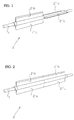
- the drawing shows the blade arrangement in accordance with the invention, the said arrangement embodying a shaft 1 reaching across the entire veneer web that is to be cut and the two blade elements 2' and 2'' supported by it.
- the blade elements may be rotated independently on the shaft 1 and they are provided with their own rotating apparatus.
- the blade elements 2' and 2'' execute cutting operations on the web halves independently on one another in order to remove faulty spots from their respective halves.
- the slitting of the veneer web coming to the slitter is discontinued and the control for the blade elements 2' and 2'' are combined to obey the same command, this command usually being to cut the veneer web into sheets of certain width.
- this command usually being to cut the veneer web into sheets of certain width.
- the blade elements 2' and 2'' are, of course, angularly in unison with one another and form a contiguous blade reaching across the veneer web.
- the said joint-function model may include situations in which the veneer web contains faulty spots that need to be removed. When this is the case, the faulty spots are cut off in strips extending across the entire veneer web by the blade elements 2' and 2'' working in unison.
- the blade elements 2' and 2'' are composed of two blades 2'a, 2'b, and correspondingly 2''a , 2''b
- the blade elements may consist more blades; e.g. four blades positioned at even angles on a shaft. Even one blade per blade element 2' and 2'' forms a functioning solution.
Landscapes
- Life Sciences & Earth Sciences (AREA)
- Engineering & Computer Science (AREA)
- Forests & Forestry (AREA)
- Mechanical Engineering (AREA)
- Wood Science & Technology (AREA)
- Manufacturing & Machinery (AREA)
- Manufacture Of Wood Veneers (AREA)
- Milling, Drilling, And Turning Of Wood (AREA)
Abstract
Claims (6)
- Dispositif pour couper une bande de bois de placage en feuilles d'une certaine largeur et/ou pour éliminer les points défectueux au moyen d'une lame de coupe (2) qu'on peut faire tourner d'une manière réglée sur un arbre (1), ladite lame (2) s'étendant sensiblement transversalement d'un bord à l'autre de ladite bande de bois de placage et se prêtant à une rotation en contact de coupe avec la bande pour exécuter une coupe transversale, d'une manière telle que la lame suit le mouvement de la bande de bois de placage, caractérisé en ce que la lame (2) est constituée de deux parties,réglables indépendamment (2',2''),le long de l'arbre (1).
- Dispositif suivant la revendication 1, caractérisé en ce que chacune des parties de lame (2', 2'') s'étend sur la moitié de la largeur de la bande de bois de placage à couper.
- Dispositif suivant la revendication 1 ou 2, caractérisé en ce que les deux parties de lame comprennent deux éléments de lame (2'a,2'b,2''a,2''b) mutuellement opposés par rapport à l'arbre (1).
- Dispositif suivant une quelconque des revendications 1 à 3, caractérisé en ce que la lame (2) est agencée de manière à couper le placage contre un rouleau d'appui tout en butant en même temps à l'arrière sur un organe support.
- Dispositif suivant la revendication 4, caractérisé en ce que l'arbre de lame (1) est soumis à une contrainte de traction.
- Dispositif suivant une quelconque des revendications 1 à 3, caractérisé en ce que la lame (2) est montée sur un arbre massif (1) qui est assez robuste pour fournir à la lame un support suffisant pour l'exécution de l'opération de coupe du bois de placage.
Applications Claiming Priority (3)
| Application Number | Priority Date | Filing Date | Title |
|---|---|---|---|
| FI913111A FI87431C (fi) | 1991-06-26 | 1991-06-26 | Anordning foer kapning av faner |
| FI913111 | 1991-06-26 | ||
| PCT/FI1992/000091 WO1993000206A1 (fr) | 1991-06-26 | 1992-03-27 | Dispositif servant a couper le bois de placage du contre-plaque |
Publications (2)
| Publication Number | Publication Date |
|---|---|
| EP0591225A1 EP0591225A1 (fr) | 1994-04-13 |
| EP0591225B1 true EP0591225B1 (fr) | 1995-08-23 |
Family
ID=8532798
Family Applications (1)
| Application Number | Title | Priority Date | Filing Date |
|---|---|---|---|
| EP92907313A Expired - Lifetime EP0591225B1 (fr) | 1991-06-26 | 1992-03-27 | Dispositif servant a couper le bois de placage du contre-plaque |
Country Status (6)
| Country | Link |
|---|---|
| EP (1) | EP0591225B1 (fr) |
| JP (1) | JPH06508800A (fr) |
| CA (1) | CA2109583C (fr) |
| DE (1) | DE69204286T2 (fr) |
| FI (1) | FI87431C (fr) |
| WO (1) | WO1993000206A1 (fr) |
Families Citing this family (2)
| Publication number | Priority date | Publication date | Assignee | Title |
|---|---|---|---|---|
| IT1249595B (it) * | 1991-02-12 | 1995-03-09 | Cremona Angelo & Figlio | Stazione di taglio in fogli per sfogliati di legno |
| FR2766476B1 (fr) * | 1997-07-22 | 1999-09-03 | Ceca Sa | Adsorbant zeolitique ameliore pour la separation des gaz de l'air et son procede d'obtention |
Family Cites Families (6)
| Publication number | Priority date | Publication date | Assignee | Title |
|---|---|---|---|---|
| SE395235B (sv) * | 1974-05-02 | 1977-08-08 | Durand Machine Co Ltd | Roterande fanersker |
| IT1129514B (it) * | 1980-01-14 | 1986-06-04 | Colombo & Cremona Sas | Perfezionamenti alle taglierine rotative per adattarle al taglio di sfogliati in legno |
| IT206331Z2 (it) * | 1985-09-25 | 1987-08-10 | Cremona Angelo & Figlio | Taglierina rotante perfezionata per materiali in foglia, in particolare sfogliati di legno. |
| JPH0635125B2 (ja) * | 1986-02-13 | 1994-05-11 | 株式会社名南製作所 | ベニヤ単板の切断装置 |
| US4726271A (en) * | 1986-10-21 | 1988-02-23 | Elliott Bay Industries, Inc. | Rotary cutting machine |
| FI80230B (fi) * | 1988-05-10 | 1990-01-31 | Plymachine Engineering Oy | Fanerskaerare. |
-
1991
- 1991-06-26 FI FI913111A patent/FI87431C/fi active
-
1992
- 1992-03-27 JP JP4506882A patent/JPH06508800A/ja active Pending
- 1992-03-27 CA CA002109583A patent/CA2109583C/fr not_active Expired - Fee Related
- 1992-03-27 EP EP92907313A patent/EP0591225B1/fr not_active Expired - Lifetime
- 1992-03-27 WO PCT/FI1992/000091 patent/WO1993000206A1/fr not_active Ceased
- 1992-03-27 DE DE69204286T patent/DE69204286T2/de not_active Expired - Fee Related
Also Published As
| Publication number | Publication date |
|---|---|
| JPH06508800A (ja) | 1994-10-06 |
| FI87431B (fi) | 1992-09-30 |
| DE69204286D1 (de) | 1995-09-28 |
| DE69204286T2 (de) | 1996-05-09 |
| CA2109583A1 (fr) | 1993-01-07 |
| WO1993000206A1 (fr) | 1993-01-07 |
| FI913111A0 (fi) | 1991-06-26 |
| CA2109583C (fr) | 2004-02-03 |
| EP0591225A1 (fr) | 1994-04-13 |
| FI87431C (fi) | 1993-01-11 |
Similar Documents
| Publication | Publication Date | Title |
|---|---|---|
| EP0378097B1 (fr) | Contre-plaqué comportant peu de courbures et d'ondulations fabriqué en utilisant un placage à fibres non rectilignes et procédé pour la fabrication d'un tel contre-plaqué | |
| CA2109870A1 (fr) | Appareil pour supporter et immobiliser un rouleau de papier au moment de le couper | |
| FI77593C (fi) | Staolkonstruktion som anvaends vid laengsskaerning av materialbanor. | |
| US3508460A (en) | Paperboard slitting device | |
| EP0591225B1 (fr) | Dispositif servant a couper le bois de placage du contre-plaque | |
| US5826481A (en) | Device for cutting plywood veneer | |
| US4254677A (en) | Slitter blade positioning means | |
| US3991800A (en) | Log de-barking machine | |
| ATE152390T1 (de) | Bogenschneidmaschine für geschältes holzfurnier | |
| ATE27782T1 (de) | Einrichtung zum schneiden von laenglichen papierrollen. | |
| US4139034A (en) | Waferizer | |
| WO1995015242A1 (fr) | Dispositif et procede de retrecissement d'un rouleau de papier | |
| US3596547A (en) | Cutting tool | |
| SU793781A1 (ru) | Устройство дл продольной резкипОлиМЕРНыХ МАТЕРиАлОВ | |
| JPS6247687B2 (fr) | ||
| JP3089028B2 (ja) | 薄膜体ロールの切断方法 | |
| JP2689170B2 (ja) | 薄膜体ロールの切断方法 | |
| SE9901487D0 (sv) | Metod för avlägsning av damm i anslutning till arkskärmaskinen i en massatorkmaskin eller liknande och arrangemang för utförande av metoden | |
| GB2309768A (en) | An insulation material which may be divided along lines of weakness | |
| FI80230B (fi) | Fanerskaerare. | |
| KR100408899B1 (ko) | 시어링 장치 | |
| SU1235741A1 (ru) | Устройство дл продольной резки листовой резины | |
| JPS60207712A (ja) | スリツタにおける切断方法 | |
| WO1992011979A1 (fr) | Coupoir | |
| JPH0631683A (ja) | 紙状体の切断巻取り装置 |
Legal Events
| Date | Code | Title | Description |
|---|---|---|---|
| PUAI | Public reference made under article 153(3) epc to a published international application that has entered the european phase |
Free format text: ORIGINAL CODE: 0009012 |
|
| 17P | Request for examination filed |
Effective date: 19930624 |
|
| AK | Designated contracting states |
Kind code of ref document: A1 Designated state(s): DE FR IT |
|
| RAP1 | Party data changed (applicant data changed or rights of an application transferred) |
Owner name: RAUTE WOOD PROCESSING MACHINERY OY |
|
| 17Q | First examination report despatched |
Effective date: 19941115 |
|
| GRAA | (expected) grant |
Free format text: ORIGINAL CODE: 0009210 |
|
| AK | Designated contracting states |
Kind code of ref document: B1 Designated state(s): DE FR IT |
|
| PG25 | Lapsed in a contracting state [announced via postgrant information from national office to epo] |
Ref country code: FR Free format text: THE PATENT HAS BEEN ANNULLED BY A DECISION OF A NATIONAL AUTHORITY Effective date: 19950823 |
|
| REF | Corresponds to: |
Ref document number: 69204286 Country of ref document: DE Date of ref document: 19950928 |
|
| ITF | It: translation for a ep patent filed | ||
| EN | Fr: translation not filed | ||
| PLBE | No opposition filed within time limit |
Free format text: ORIGINAL CODE: 0009261 |
|
| 26N | No opposition filed | ||
| PGFP | Annual fee paid to national office [announced via postgrant information from national office to epo] |
Ref country code: IT Payment date: 20090127 Year of fee payment: 18 Ref country code: DE Payment date: 20090407 Year of fee payment: 18 |
|
| PG25 | Lapsed in a contracting state [announced via postgrant information from national office to epo] |
Ref country code: DE Free format text: LAPSE BECAUSE OF NON-PAYMENT OF DUE FEES Effective date: 20101001 |
|
| PG25 | Lapsed in a contracting state [announced via postgrant information from national office to epo] |
Ref country code: IT Free format text: LAPSE BECAUSE OF NON-PAYMENT OF DUE FEES Effective date: 20100327 |