EP0591269B1 - Procede et appareil a melanger et distribuer de constituants multiples - Google Patents
Procede et appareil a melanger et distribuer de constituants multiples Download PDFInfo
- Publication number
- EP0591269B1 EP0591269B1 EP92912057A EP92912057A EP0591269B1 EP 0591269 B1 EP0591269 B1 EP 0591269B1 EP 92912057 A EP92912057 A EP 92912057A EP 92912057 A EP92912057 A EP 92912057A EP 0591269 B1 EP0591269 B1 EP 0591269B1
- Authority
- EP
- European Patent Office
- Prior art keywords
- nozzle
- mixing
- dispensing
- component
- opening
- Prior art date
- Legal status (The legal status is an assumption and is not a legal conclusion. Google has not performed a legal analysis and makes no representation as to the accuracy of the status listed.)
- Expired - Lifetime
Links
- 238000002156 mixing Methods 0.000 title claims abstract description 178
- 239000000463 material Substances 0.000 title claims description 47
- 238000000034 method Methods 0.000 title claims description 19
- 238000002347 injection Methods 0.000 claims description 32
- 239000007924 injection Substances 0.000 claims description 32
- 238000007789 sealing Methods 0.000 claims description 32
- 239000007921 spray Substances 0.000 claims description 13
- 238000004891 communication Methods 0.000 claims description 7
- 230000003068 static effect Effects 0.000 claims description 5
- 238000004140 cleaning Methods 0.000 abstract description 4
- 239000007788 liquid Substances 0.000 description 51
- 229920005830 Polyurethane Foam Polymers 0.000 description 13
- 239000011496 polyurethane foam Substances 0.000 description 13
- 239000002904 solvent Substances 0.000 description 12
- 239000000047 product Substances 0.000 description 10
- 239000006260 foam Substances 0.000 description 9
- 238000005516 engineering process Methods 0.000 description 8
- 239000012948 isocyanate Substances 0.000 description 6
- 150000002513 isocyanates Chemical class 0.000 description 6
- 238000006116 polymerization reaction Methods 0.000 description 6
- 238000010107 reaction injection moulding Methods 0.000 description 5
- 229920005989 resin Polymers 0.000 description 5
- 239000011347 resin Substances 0.000 description 5
- 238000006243 chemical reaction Methods 0.000 description 4
- 230000007246 mechanism Effects 0.000 description 4
- 229920005862 polyol Polymers 0.000 description 4
- 150000003077 polyols Chemical class 0.000 description 4
- JOYRKODLDBILNP-UHFFFAOYSA-N Ethyl urethane Chemical compound CCOC(N)=O JOYRKODLDBILNP-UHFFFAOYSA-N 0.000 description 3
- 239000000443 aerosol Substances 0.000 description 3
- 230000000712 assembly Effects 0.000 description 3
- 238000000429 assembly Methods 0.000 description 3
- 239000003054 catalyst Substances 0.000 description 3
- 238000010276 construction Methods 0.000 description 3
- 238000005520 cutting process Methods 0.000 description 3
- 238000013461 design Methods 0.000 description 3
- 230000009977 dual effect Effects 0.000 description 3
- 238000004519 manufacturing process Methods 0.000 description 3
- 238000000465 moulding Methods 0.000 description 3
- 238000012856 packing Methods 0.000 description 3
- 229920000728 polyester Polymers 0.000 description 3
- 238000007711 solidification Methods 0.000 description 3
- 230000008023 solidification Effects 0.000 description 3
- 229920001730 Moisture cure polyurethane Polymers 0.000 description 2
- 230000008878 coupling Effects 0.000 description 2
- 238000010168 coupling process Methods 0.000 description 2
- 238000005859 coupling reaction Methods 0.000 description 2
- 230000000994 depressogenic effect Effects 0.000 description 2
- -1 ethylene, propylene, tetramethylene Chemical group 0.000 description 2
- 238000009413 insulation Methods 0.000 description 2
- 238000004806 packaging method and process Methods 0.000 description 2
- 229920003023 plastic Polymers 0.000 description 2
- 239000004033 plastic Substances 0.000 description 2
- 230000008569 process Effects 0.000 description 2
- 239000000376 reactant Substances 0.000 description 2
- 238000007790 scraping Methods 0.000 description 2
- ICLCCFKUSALICQ-UHFFFAOYSA-N 1-isocyanato-4-(4-isocyanato-3-methylphenyl)-2-methylbenzene Chemical compound C1=C(N=C=O)C(C)=CC(C=2C=C(C)C(N=C=O)=CC=2)=C1 ICLCCFKUSALICQ-UHFFFAOYSA-N 0.000 description 1
- 239000004604 Blowing Agent Substances 0.000 description 1
- 229920005123 Celcon® Polymers 0.000 description 1
- 229920004943 Delrin® Polymers 0.000 description 1
- 239000004721 Polyphenylene oxide Substances 0.000 description 1
- 229920002396 Polyurea Polymers 0.000 description 1
- 230000009471 action Effects 0.000 description 1
- 125000003118 aryl group Chemical group 0.000 description 1
- 239000004568 cement Substances 0.000 description 1
- 239000011248 coating agent Substances 0.000 description 1
- 238000000576 coating method Methods 0.000 description 1
- 238000009833 condensation Methods 0.000 description 1
- 230000005494 condensation Effects 0.000 description 1
- 238000011109 contamination Methods 0.000 description 1
- 230000007812 deficiency Effects 0.000 description 1
- 230000002950 deficient Effects 0.000 description 1
- 125000005442 diisocyanate group Chemical group 0.000 description 1
- 230000007613 environmental effect Effects 0.000 description 1
- 230000008020 evaporation Effects 0.000 description 1
- 238000001704 evaporation Methods 0.000 description 1
- 239000012467 final product Substances 0.000 description 1
- 239000012530 fluid Substances 0.000 description 1
- 238000005187 foaming Methods 0.000 description 1
- 239000003292 glue Substances 0.000 description 1
- 150000002334 glycols Chemical class 0.000 description 1
- 238000012423 maintenance Methods 0.000 description 1
- 230000007257 malfunction Effects 0.000 description 1
- 239000000203 mixture Substances 0.000 description 1
- 238000012986 modification Methods 0.000 description 1
- 230000004048 modification Effects 0.000 description 1
- 229920000570 polyether Polymers 0.000 description 1
- 229920001228 polyisocyanate Polymers 0.000 description 1
- 239000005056 polyisocyanate Substances 0.000 description 1
- 229920002635 polyurethane Polymers 0.000 description 1
- 239000004814 polyurethane Substances 0.000 description 1
- 238000004382 potting Methods 0.000 description 1
- 238000009877 rendering Methods 0.000 description 1
- 238000007493 shaping process Methods 0.000 description 1
- 239000011343 solid material Substances 0.000 description 1
- 238000005507 spraying Methods 0.000 description 1
- 230000007480 spreading Effects 0.000 description 1
- 238000003892 spreading Methods 0.000 description 1
- 239000000126 substance Substances 0.000 description 1
- 229920001187 thermosetting polymer Polymers 0.000 description 1
- 238000011144 upstream manufacturing Methods 0.000 description 1
- 239000011800 void material Substances 0.000 description 1
- 239000002699 waste material Substances 0.000 description 1
Images




Classifications
-
- B—PERFORMING OPERATIONS; TRANSPORTING
- B29—WORKING OF PLASTICS; WORKING OF SUBSTANCES IN A PLASTIC STATE IN GENERAL
- B29B—PREPARATION OR PRETREATMENT OF THE MATERIAL TO BE SHAPED; MAKING GRANULES OR PREFORMS; RECOVERY OF PLASTICS OR OTHER CONSTITUENTS OF WASTE MATERIAL CONTAINING PLASTICS
- B29B7/00—Mixing; Kneading
- B29B7/74—Mixing; Kneading using other mixers or combinations of mixers, e.g. of dissimilar mixers ; Plant
- B29B7/7438—Mixing guns, i.e. hand-held mixing units having dispensing means
-
- B—PERFORMING OPERATIONS; TRANSPORTING
- B29—WORKING OF PLASTICS; WORKING OF SUBSTANCES IN A PLASTIC STATE IN GENERAL
- B29B—PREPARATION OR PRETREATMENT OF THE MATERIAL TO BE SHAPED; MAKING GRANULES OR PREFORMS; RECOVERY OF PLASTICS OR OTHER CONSTITUENTS OF WASTE MATERIAL CONTAINING PLASTICS
- B29B7/00—Mixing; Kneading
- B29B7/30—Mixing; Kneading continuous, with mechanical mixing or kneading devices
- B29B7/32—Mixing; Kneading continuous, with mechanical mixing or kneading devices with non-movable mixing or kneading devices
- B29B7/325—Static mixers
Definitions
- This invention generally relates to a plural component dispensing apparatus adapted to mix and dispense multiple components therefrom, and a mixing nozzle assembly for use with dispensing apparatus of this type. More specifically, the invention relates to a dispensing device for forming and dispensing a product by mixing a plurality of chemically reactive components, the device including a replaceable mixing nozzle which completely isolates and separates the reactants from the dispenser body and allows the components to be more effectively mixed to provide better results and avoid problems associated with such apparatus.
- a plurality of chemically reactive materials with one another, which may then be dispensed from a suitable dispensing apparatus.
- a plurality of components are mixed together to form a polyester, polyurea, or polyether resin foam product.
- the plural components to be mixed may comprise an isocyanate and polyol or other catalyst, each of which is generally stable and will stay in a liquid state for an extended period of time. Upon mixing of these components in the proper amount and in a thorough manner, a chemical reaction will cause polymerization of the components.
- a blowing agent may be used to cause the reactive polyurethane to foam, cure and cross-link to form a solid material.
- Such materials are utilized as industrial foams for packaging, insulation, in the shaping and coating of articles or other uses.
- the requirement for mixing the components and thereafter dispensing the formed product has led to the design of a variety of dispensing apparatus adapted to mix plural components. In the design of dispensing apparatus utilized to mix plural components in this manner, the hardening of the mixed components within the dispensing apparatus may clog or block the dispensing passages and ports of the apparatus such that the dispensing device will be rendered inoperative.
- the dispensing apparatus may be cleaned by the use of solvents introduced into the device to wash out the individual components as well as the hardened resin material formed upon mixing.
- solvents introduced into the device to wash out the individual components as well as the hardened resin material formed upon mixing.
- the use of such solvents is undesirable as the evaporation of the solvents may result in condensation of moisture which will interfere with the chemical reaction and may affect the quality of the formed product such as a polyurethane foam.
- Other drawbacks of such devices include the inability to properly meter the separate components and inadequate mixing of the components within the apparatus.
- Reaction Injection Molding Another technology used that has evolved to replace solvent flush technology is Reaction Injection Molding (RIM) in this method the materials are separately entered into a mixing chamber that is mechanically cleaned by a plunger which mechanically moves through the bore after the reaction to displace the reactants and clean the walls of the mixing chamber.
- RIM Reaction Injection Molding
- U.S. patent 4,427,153 a plural component dispensing gun is disclosed which includes a spray gun nozzle having a one piece mixing chamber with axially displaced inlets stated to provide better mixing and having a sealing arrangement to prevent leakage of the separate components from the spray nozzle.
- U.S. patent 4,023,733 a foam dispensing gun is disclosed as having a mixing chamber with liquid entry ports, wherein one liquid entry port is spaced upstream from the other to prevent undesirable cross-feeding between the inlet ports. This construction is also stated to provide better mixing of the plural components.
- a dispensing apparatus is shown as having a mixing chamber within the nozzle thereof into which the plural materials are introduced by separate inlet ports.
- the liquid components enter the mixing nozzle at an angle such that the separate streams of liquid are directed toward one another for better mixing.
- a foam dispensing gun includes a disposable nozzle for mixing and dispensing separate fluid components.
- the foam dispensing gun is designed to be inoperative in the absence of a dispensing nozzle on the gun and allows the nozzle to be removed for reloading.
- a urethane foam gun is disclosed which includes dual plug valves for control of separate streams of the plural components and a second gun-mounted valve which controls a solvent flush for cleaning. It is again found that such designs have drawbacks in properly maintaining the dispensing device in an operative condition and avoiding the blockage of internal passageways and nozzle of the apparatus.
- British Patent Specification No 2177942 on which disclosure the preambles of independent claims 1 and 9 are based, discloses a chemical mixing and dispensing gun which incorporates valve controlled internal passages communicating with a plugged opening the gun barrel communicating with a spray tip.
- a trigger controls a rotatable valve element by which flow of material through the internal passage is controlled. Sealing rings to ensure proper opening and closing form an integral part of the rotatable valve element.
- the present invention provides a mixing and dispensing apparatus comprising:
- the mixing head has at least two component feed systems, each for a component to be mixed and dispensed, said component feed systems including an outlet port and a valve means disposed to selectively allow flow of a said component to said outlet port, and said nozzle including a mixing chamber having a plurality of injection channels formed therein which communicate with said at least one inlet port, said injection channels having a plurality of injection ports communicating with said mixing chamber, wherein each of said plural components will be selectively fed through said component feed systems, and to said nozzle for mixing and dispensing thereof.
- the plurality of injection ports in said mixing chamber each include at least one inlet opening into said mixing chamber, and are offset with respect to one another such that material entering said mixing chamber through said inlet openings will be directed against an opposing wall of said mixing chamber for impingement mixing of said plural components.
- the actuating means is adapted to include an integral sealing means at a location of communication between said at least one outlet port of said component feed system and said at least one inlet port of said nozzle when said dispensing nozzle is positioned within said opening to seal these ports and prevent leakage of material, such that upon operation of said actuating means, material will be supplied through said at least one component feed system and said at least one outlet port to said at least one inlet port of said nozzle for mixing and dispensing thereof through said nozzle.
- the invention provides a method of mixing and dispensing materials comprising the steps of:
- the nozzle includes a plurality of nozzle tips integrally formed therein, with each of said plurality of nozzle tips yielding a different spray pattern for material dispensed therefrom, said method further characterised by the steps of selectively exposing one of said plurality of nozzle tips integrally formed in said dispensing nozzle for the desired spray pattern, and supplying at least one material to be mixed and dispensed through said at least one feed system to flow into said nozzle for mixing and dispensing thereof through said exposed nozzle tip.
- the invention provides a method of mixing and dispensing materials comprising the steps of:
- the invention provides a method of mixing and dispensing materials comprising the steps of:
- a multi-component dispensing apparatus 10 which is particularly suitable for mixing and dispensing two liquids, such as liquid organic resins and liquid isocyanates, which react to form a polyurethane foam when mixed.
- the apparatus 10 is generally formed as a gun to facilitate dispensing operations, and comprises a mixing head 12 and handle section 14.
- the apparatus 10 is preferably formed by molding techniques using structural plastic materials such as Styrene-K-resins, Celcon, Delrin or polyester, but may be constructed by other suitable techniques or materials.
- Fitted within and extending from the mixing head 12 is a mixing and dispensing nozzle 16 which includes at least one mixing chamber 18.
- the nozzle 16 and mixing chamber 18 may also be formed by molding techniques, such that the entire assembly is easily and cost-effectively manufactured.
- the mixing chamber 18 communicates with individual component feed systems having internal passages 20 and a valve means 22 for each component to be mixed in the system.
- the internal passages 20 also communicate with a plurality of inlet ports 24 which may be coupled to a source of a liquid component under pressure such as by hoses 26 or alternatively by portable pressurised aerosol cylinders or the like.
- the valve means 22 is actuated by actuating means in the form of a trigger member 28 to allow flow of the liquid components within the internal passages 20 and to mixing chamber 18 to be dispensed through dispensing nozzle 16.
- the multi-component dispensing system of the invention is particularly useful for polyurethane foam systems, wherein a plurality of reactive components are mixed and dispensed in a foaming process
- the apparatus may also be useful in other applications such as with various thermosetting plastics, spray catalyst glues, gel coats or the like.
- the components to be mixed will be chemically reactive with one another, but the device may also be used with non-reactive liquids which are to be mixed and dispensed.
- the invention will be described with respect to a two component system, it will be appreciated that other component feed systems may be provided for a third or more components as desired.
- the mixing head 12 includes first and second valve cavities 30 and 32 respectively, in each of which is provided a valve means to be described in more detail hereinafter.
- the valve cavities 30 and 32 each include an inlet orifice 33 and 34 respectively which cooperate with component feed cavities 36 and 38, coupled to a source of a component to be mixed under pressure.
- the valve cavities 30 and 32 also communicate via metering ports with separate internal passages 40 and 42 which include first and second outlet orifices 43 and 44 respectively.
- the outlet ports 43 and 44 communicate with a nozzle opening 46 formed in a center region of mixing head 12 and extending therethrough.
- a collar 49 which extends outwardly from mixing head 12 to accept a portion of the dispensing nozzle 16. More particularly, the nozzle opening 46 is designed to accommodate the shank portion 48 of dispensing nozzle 16 in tight frictional engagement therein for use of the apparatus.
- the collar 49 may include a narrow, elongated slit 50 adapted to receive a key pin 52 formed adjacent the shank portion 48 of dispensing nozzle 16. Proper alignment of the dispensing nozzle 16 within the nozzle opening 46 for use is easily achieved by positioning key pin 52 within and seated against the back edge of slot 50.
- the dispensing nozzle 16 may be provided with a plurality of flanges 54 which allow manipulation of the dispensing nozzle 16 for proper alignment of the key pin 52 within guide slot 50.
- the outlet orifices 43 and 44 in mixing head 12 will be coupled to injection ports 55 and 56 formed on shank portion 48 of the dispensing nozzle 16.
- the nozzle opening 46 also communicates with an elongated trigger cavity 58 which extends downwardly from the nozzle opening 46 and is adapted to house a trigger mechanism as will be hereinafter described.
- a slot 60 is provided along the upper portion of the nozzle opening 46 in association with the trigger cavity 58.
- the cavity 58 includes a sloping surface 62 such that the trigger cavity communicates with the nozzle opening 46 over the portion of nozzle opening 46 extending from a position adjacent the outlet orifices 43 and 44 communicating therewith.
- the handle portion 14 is seen to include a cavity 64 to house the flexible pressurized feed lines for each component to be mixed.
- the feed lines may be inserted into the component feed cavities 36 and 38 using a quick coupling fitting as an example, wherein the feed assemblies will be sealed within cavities 36 and 38 by suitable sealing means and may be locked in place by means of screws 66 or a similar locking mechanism.
- Liquid components to be mixed are directed through passages 33 and 34 from feed cavities 36 and 38 which communicate with the valve cavities 30 and 32.
- the valve cavities 30 and 32 will in turn communicate with internal passages 40 and 42 through metering orifices to be directed to the outlet ports 43 and 44 for injection into the dispensing nozzle 16.
- the trigger assembly 28 is shown in its attached position relative to mixing head 12.
- the trigger mechanism 28 may include an elongated trigger arm 68 extending in a position adjacent handle portion 14 of the mixing head 12 such that the trigger 28 may be easily held and operated in association with handle 14.
- the trigger assembly 28 may be mounted to mixing head 12 by means of a pivot pin 70 so as to be pivotable within the trigger cavity 58.
- the trigger assembly 28 includes an upper hammer portion 72 which is adapted to act upon a valve actuating structure to be described hereinafter, as well as to perform the dual function of enabling the dispensing apparatus to be rendered inoperative or non-operational when desired and to eject the dispensing nozzle 16 from mixing head 12.
- the trigger cavity 58 in which the trigger member 28 is housed again includes the downwardly sloping bottom surface 62, and the trigger member 28 is pivotable about point 70 such that the trigger member 28 will be pivotable in both forward and backward directions in the assembly.
- the trigger arm 68 may be depressed toward handle portion 14 to allow the components under pressure to flow through the internal passages to the dispensing nozzle 16 of the apparatus.
- the trigger arm 68 may also be pulled outwardly from the handle portion 14 wherein the hammer 72 will travel within nozzle opening 46 to the extent of sloping surface 62 of trigger cavity 58.
- the trigger member 28 includes a bearing surface 74 facing inwardly and a bearing surface 76 directed outwardly from trigger cavity 58.
- the upper portion of the hammer 72 may extend above the top wall 78 of mixing head 12 to enable the desired travel to be obtained within nozzle opening 46 by hammer 72.
- the channel 60 is provided along the upper portion of nozzle opening 46.
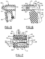
- FIG. 5 the internal passages within the mixing head 12 are shown for one of the liquid component feed systems within mixing head 12.
- the valve cavity 30 is designed to house a valve means therein, which is adapted to selectively open and close inlet port 33.
- the inlet port 33 is coupled to the component feed cavity 36 from which a supply of a liquid component will be directed under pressure.
- flow of a liquid component from inlet port 33 will proceed to internal passage 40 and then on to outlet port 43.
- the back edge of the valve cavity 30 is open to accept a suitable valve means therein and to allow valve actuating means to extend from cavity 30 for operation of the valve means.
- the nozzle opening formed in the mixing head 12 may be generally cylindrical and lies adjacent the valve cavities of the mixing head 12 with its axis substantially parallel to the axis of the valve cavities 30 and 32.
- the top wall 78 of the mixing head 12 encloses nozzle opening 46 over a portion of its length, but is cut away at channel 60, which as stated previously allows hammer portion 72 of trigger assembly 28 to pass therethrough.
- the trigger assembly is movable from the operational, valve-actuating position as seen in ghost at 72a, to a non-operational nozzle ejecting position indicated in ghost at 72b within nozzle opening 46.
- the outlet port 43 of the liquid component feed system is also seen to enter nozzle opening 46 at a side portion thereof within the enclosed space of opening 46.
- Situated about the outlet port 43 may be provided an integrally formed sealing land 80 formed circularly about outlet port 43.
- the sealing land 80 may be adapted to frictionally engage the shank portion of the dispensing nozzle to be used with mixing head 12 and about an inlet port provided on the dispensing nozzle.
- the sealing land 80 will prevent leakage of a liquid component beyond the area immediately adjacent outlet port 43.
- additional sealing members 82 positioned on either side of outlet port 43 which may be integrally formed in the nozzle opening 46 to simulate O ring seals about the outlet ports 43 and 44 respectively.
- the sealing means 82 may provide additional protection against leakage of the liquid components from the dispensing apparatus as desired.
- mixing head 12 of the preferred embodiment will be comprised of two liquid component feed systems adapted to feed individual liquid components in a separated fashion to the location of a mixing and dispensing nozzle used in the apparatus. Again, additional liquid feed systems may be provided and the configuration modified accordingly as desired.
- valve means 84 which in the preferred embodiment is a needle valve extending into the front portion of valve cavity 30 so as to seal the inlet ports 36 and 38 respectively.
- the valve means may be sealed about its periphery adjacent to inlet ports 36 and 38 by means of an O-ring seal 89 or the like, which ensures that none of the liquid components can enter the valve cavities 30 and 32 to avoid blockage and malfunction of the liquid feed systems.
- the valve means may also include a valve stem 86 extending towards the back of mixing head 12 within valve cavity 30.
- the valve stem 86 may be surrounded by a bias spring 88 extending between the packing head of the needle valve 84 and rear packing member 90, which together completely seal the valve cavity 30.
- a locking bonnet 92 may be used to maintain the valve configuration within the valve cavity 30 with the valve stem 86 being sealed at rear packing 90 and extending outwardly from valve cavity 30.
- a valve actuating member 94 is secured to the rear of the mixing head 12 and to the valve stems 86 extending from valve cavities 30 and 32 respectively by suitable securing means such as a locking nut 96.
- the valve actuating member 94 is therefore secured to both valve stems 86, and has a mid portion thereof positioned adjacent trigger cavity 58.
- the bearing surface 76 on hammer portion 72 of trigger assembly 28 is adapted to act on valve actuation member 94. In this way, upon depression of the trigger assembly 28, the valve actuating member 94 will be urged outwardly against the force of bias spring 88 to open needle valve 84 and allow flow through inlet ports 36 and 38 to internal passages 40 and 42 respectively.
- the needle valve 84 is adapted to move in a substantially perpendicular manner relative to inlet ports 33 and 34.
- the valve members Upon actuation of the needle valve 84, the valve members will perform a scraping action at the location of the inlet ports 33 and 34 such that these ports will remain free from blockage and to ensure free flow of the liquid components therethrough.
- scraping accomplishes self-cleaning of the internal passages in a continuous manner to ensure proper operation of the apparatus without having to use solvents or the like.
- the internal passages 40 and 42 may be drilled into the mixing head 12 and thereafter sealed by screw plugs 99, a suitable cement or the like.
- valve actuating member 94 may be modified to allow selective actuation of either of the valve assemblies alone or partially.
- a sealing plug 97 is disposed within nozzle opening 46, which as seen in Fig. 7 is positioned with the dispensing device in its operational mode.
- the hammer portion 72 of trigger assembly 28 lies directly adjacent the rear surface 98 of sealing plug 97 as seen in Fig. 7, and at its other end will lie adjacent the shank 48 of a dispensing nozzle assembly positioned within nozzle opening 46 as seen in ghost partial outline.
- a disposable mixing and dispensing nozzle could be utilized, wherein after use, the sealing plug is moved to eject the disposable nozzle and seal the outlet ports of the liquid component feed systems until use of the apparatus is again desired. In this way, no solidification of the liquid components to be mixed and dispensed can occur and the apparatus is indefinitely placed in a non-operational mode.
- a replaceable dispensing nozzle assembly may simply be pushed into the nozzle opening 46 against sealing plug 97 until operatively coupled to outlet ports 43 and 44 formed in nozzle opening 46, and to the position as shown in solid line of Fig. 7.
- nozzle assembly 16 of the invention is shown in more detail.
- any suitable dispensing nozzle may be used in the dispensing apparatus of the invention, an improved nozzle assembly in accordance with the invention is preferably used in conjunction therewith.
- the nozzle assembly 16 comprises an elongated tubular member, which in the preferred embodiment has an outwardly extending alignment key pin 52, adapted to be positioned within a slot formed in the nozzle opening of the dispensing apparatus. In this way, the alignment of nozzle 16 within nozzle opening 46 is ensured to enable the outlet ports 43 and 44 of the liquid component feed systems to coact with nozzle assembly 16 in a desired manner.
- the shank portion 48 of the nozzle assembly is to be inserted within the nozzle opening 46 of mixing head 12 of the dispensing apparatus, such that injection ports 55 and 56 formed on opposed sides of the shank portion 48 will be positioned in alignment with outlet ports 43 and 44 respectively of the dispensing apparatus.
- the injection ports 55 and 56 are in turn connected to an insertable mixing chamber 100 positioned within shank portion 48.
- the insertable mixing chamber 100 will thereby seal the open end 102 of the nozzle assembly adjacent the shank portion 48 of the assembly.
- the interior of the tubular nozzle adjacent end 102 may be provided with recessed areas 103 and 104 which are adapted to engage shoulder portions 106 formed on mixing chamber insert 100, such that the mixing chamber insert will be snap fit in the proper position within shank portion 48.
- a first embodiment of the mixing chamber insert 100 to be used in conjunction with the dispensing nozzle 16 of the invention is shown.
- the particular components which are to be mixed and dispensed using the apparatus of the invention may have distinct characteristics which require that the mixing chamber be modified according to these characteristics.
- the mixing chamber insert 100 comprises an elongated body member, which may be substantially cylindrical in shape and be dimensioned so as to tightly fit within the tubular interior of shank portion 48 of the nozzle assembly 16 through its rear open end 102.
- the body portion of the mixing chamber insert 102 may include integrally formed outwardly extending sealing shoulder portions 106.
- the shoulder portions 106 essentially comprise integrally formed O ring seals to prevent the leakage of liquid components therefrom.
- the mixing chamber 100 is formed to have two opposed slots or channels 110 along each side thereof which coact with the injection ports 55 and 56 formed in the nozzle 16.
- the channels 110 are adapted to extend longitudinally along a substantial portion of the length of the mixing chamber insert 100 such that material entering the channel will be disbursed over a larger area.
- the actual mixing chamber is formed as a central opening 112 having an open end which faces the interior of the dispensing nozzle 16 in which the insert 100 is to be positioned, and having its other end closed as seen in Fig. 9.
- the central opening 112 constitutes the chamber in which plural components are to be mixed utilizing the technique of impingement mixing of the individual components within chamber 112.
- the mixing chamber 112 communicates with each of the channels 110 formed in insert 100 by means of a plurality of injection ports 114, 115, 116 and 117 connected to each channel 110 respectively. Also as seen in Fig. 9, each of the injection ports 114, 115, 116 and 117 are axially offset with respect to one another, and in relation to each channel 110 are positioned linearly so as to communicate with each of the respective channels 110.
- each of the liquid components is directed under pressure into mixing chamber 112 and against an opposing wall of chamber 112 as indicated by flow lines in chamber 112.
- the impingement mixing obtained by directing individual streams of a liquid component against an opposing wall of the chamber to create turbulence allows better and more thorough mixing of the components with one another and avoids cross flow problems within chamber 112.
- the mixed plural components will begin polymerization within mixing chamber 112 and will continue to polymerize within interior portion 118 of the dispensing nozzle 16.
- a fully polymerized foam product will be produced and will be forced from nozzle 108 to be dispensed at the desired location.
- each of the plural components to be mixed and dispensed using the apparatus of the invention will be supplied under pressure from a component supply tank (not shown) or the like.
- a component supply tank (not shown) or the like.
- Such supply tanks are conventionally of sizes ranging from 5 to 30 liters depending upon the particular application and requirements thereof.
- Each individual liquid component is fed at a line pressure of about 50 to 250 psi, and with polyurethane foam systems as an example will be fed to the dispensing apparatus at a pressure of between 100 to 200 psi.
- the dispensing apparatus of the invention is also usable with aerosol containers being charged at a pressure of 80 to 90 psi or greater.
- the pressure lines from the component supply tanks or aerosol containers may be attached to the dispensing apparatus in component feed cavities 36 and 38 such as by use of a quick coupling fitting or the like.
- a removable dispensing nozzle 16 is positioned within nozzle opening 46 within mixing head 12 of the apparatus, and is forced into opening 46 until key pin 52 is positioned within key slot 50 as seen in Fig. 2. In this position, the injection ports 55 and 56 formed on the shank portion 48 of nozzle 16 will be aligned with outlet ports 43 and 44 associated with each component feed system in mixing head 12.
- the dispensing apparatus is operational in this configuration, and the trigger member 28 may be depressed to simultaneously open the valve means associated with each component feed system to feed each liquid component through outlet ports 43 and 44, into mixing chamber 112, and to thereafter be dispensed through nozzle tip 108.
- one liquid component may comprise an organic isocyanate such as the well known MDI, TODI, or other aromatic, naphthanic, or aliphatic diisocyanates, and a polyol such as ethylene, propylene, tetramethylene other glycols or polyesters such as polyethylenepropylene adipates as an example.
- organic isocyanate such as the well known MDI, TODI, or other aromatic, naphthanic, or aliphatic diisocyanates
- a polyol such as ethylene, propylene, tetramethylene other glycols or polyesters such as polyethylenepropylene adipates as an example.
- the ratio of each of these liquid components being fed to the mixing chamber for subsequent polymerization is important, and ratio of polyisocyanate to polyol can vary from about 0.8 to 1.2 or higher to yield varied product properties and characteristics.
- the polyol may be reacted with an isocyanate to form a pre-polymer, and the pre-polymer may comprise one of the liquid components to be mixed with a diisocyanate, triisocyanate or other isocyanate to yield the final product.
- the multi-component dispensing apparatus of the invention is particularly useful with a polyurethane foam system as described, the apparatus can be used with any system in which plural components are to be mixed and dispensed, and is particularly useful where the plural components are reactive with one another, and it is desired to maintain each of the components separate from one another until mixing and dispensing is desired.
- a second stage of mixing is provided within nozzle 16 to ensure proper and thorough mixing of the plural components with one another.
- a static mixer 120 may be provided within the internal cavity 118 of nozzle 16 at a position downstream from mixing chamber insert 100, and preferably directly adjacent to the outlet opening of mixing chamber 112. In this way, material flowing from mixing chamber 112 will be directed immediately into the static mixer 120 which may provide a helical path through which the material will be forced for continued mixing thereof. It should be evident that the static mixer 120 could comprise various other configurations to accomplish additional mixing of the plural components within dispensing nozzle 16.
- Figs. 13 and 14 another alternative embodiment of the dispensing nozzle 16 is shown, wherein similar elements have been indicated by similar reference numerals therein.
- the injection ports 55 and 56 provided on shank portion 48 may have an integrally formed sealing land 121 formed there around.
- the sealing land 121 cooperates with the interior of the nozzle opening 46 formed in mixing head 12 of the dispensing apparatus, such that injection ports 55 and 56 will be completely sealed in communication with outlet ports 43 and 44 provided within nozzle opening 46.
- the sealing lands 121 may cooperate with similar sealing lands provided in association with outlet ports 43 and 44, or may simply seat on the interior of the nozzle opening 46 as desired.
- the dispensing nozzle 16 is also provided with a nozzle tip 108 having integrally formed therein a variety of nozzle tip configurations which allow the user to select a desired nozzle tip for a particular application.
- the nozzle tip 108 may be provided with a flattened, fan-shaped tip 122 which will produce a relatively flat spreading sheet spray pattern exiting nozzle 16.
- the fan-shaped nozzle tip 122 may be desirable for various spray insulation filling, packaging or other applications to more effectively distribute the dispensed product.
- the nozzle tip 122 may be simply cut off the end of the nozzle at the location of a groove 124 integrally formed about the periphery of the nozzle tip wherein a different nozzle tip configuration 126 will be exposed.
- the nozzle tip 126 may be provided as a small opening especially suitable for use in potting operations or to allow use of an attached hose coupled to the nozzle tip to allow easier access to a mold.
- Yet another nozzle tip 128 may be exposed by cutting a long groove 130 formed in the nozzle to yield a larger exit from the nozzle tip for increased flow of the mixed product from the nozzle.
- the fan-shaped tip 122 is used for spraying broad flat surfaces.
- Cutting off at groove 124 gives a smaller opening configuration 126 which finds use on a surface 1/4 to 1/5 the size of the broad flat surface.
- Cutting off at groove 130 creates a large nozzle opening 128 which effectively acts as a pour nozzle with a minimum of spray and may be used for filling a void in a cavity as an example.
- Alternative tip configurations may be provided if desired, and may be integrally formed in the nozzle assembly as described, to give the user more flexibility and tailor the dispensing apparatus to the particular application for which it is being used.
- the exterior of the nozzle 16 may be provided with a series of hose engaging raised portions conventionally used to couple a nozzle to a hose.
- metering of the various individual liquid components to the mixing chamber may be varied for each of the liquid components by varying the size of injection ports 114, 115 as compared to injection ports 116 and 117 as an example.
- the ratio of a liquid component relative to another liquid component may be more effectively controlled to improve the quality of the product produced and to achieve the desired characteristics of the product
- the mixing chamber inserts 100 may be easily produced by molding techniques, and are replaceable within the dispensing nozzle 16, a user may select the appropriate mixing chamber insert for a particular application as desired
- a different number of injection ports may be provided in each injection channel 110 formed in the mixing chamber insert. For example, three inlet ports may be provided for one component, which only two are provided for the other component
Landscapes
- Engineering & Computer Science (AREA)
- Mechanical Engineering (AREA)
- Processing And Handling Of Plastics And Other Materials For Molding In General (AREA)
- Nozzles (AREA)
- Details Or Accessories Of Spraying Plant Or Apparatus (AREA)
Claims (10)
- Dispositif de mélange et de distribution comportant :un élément formant corps ayant au moins une partie de poignée (14) et une tête de mélange (12, ladite tête de mélange ayant au moins un système d'acheminement de constituant pour alimenter au moins un constituant à mélanger, ledit système d'acheminement de constituants ayant des passages intérieurs (20) et au moins un orifice de sortie (43, 44) associé audit au moins un système d'acheminement, ledit au moins un système d'acheminement étant associé à des moyens formant vanne (22),des moyens (24) pour relier au moins une alimentation de constituant sous pression audit au moins un système d'acheminement de constituant,des moyens d'actionnement (28) qui sont associés à ladite tête de mélange en pouvant être actionnés pour agir sélectivement sur lesdits moyens formant vanne (22) pour permettre un écoulement à travers ledit au moins système d'acheminement de constituant,ladite tête de mélange (12) comportant une ouverture (46), ledit au moins un orifice de sortie (43, 44) dudit au moins un système d'acheminement étant relié à ladite ouverture, et des moyens formant bouchon (97) sont positionnés dans ladite ouverture, etune buse de distribution (16) amovible positionnée dans ladite ouverture de ladite tête de mélange (12), ayant un intérieur creux et au moins un orifice d'entrée (55, 56) communiquant avec ledit intérieur creux en correspondance avec ledit au moins un orifice de sortie (43, 44) relié à ladite ouverture, dans lequel ledit constituant est dirigé de manière sélective à travers ledit au moins un système d'acheminement de constituant, vers ledit au moins un orifice de sortie (43, 44) et à travers ledit orifice d'entrée (55, 56) jusqu'à l'intérieur de ladite buse (16) pour être distribué, caractérisé en ce que les moyens d'actionnement (28) peuvent être actionnés tout d'abord pour faire coulisser lesdits moyens formant vanne (22) à partir d'une première position vers une seconde position afin de permettre un écoulement du constituant à travers lesdits passages internes (20) et deuxièmement pour faire coulisser lesdits moyens formant bouchon (97) à partir d'une première position vers une seconde position afin d'assurer l'étanchéité dudit au moins un orifice de sortie (43, 44).
- Dispositif selon la revendication 1, caractérisé en ce que lesdits moyens formant bouchon (97) sont adaptés pour agir sur une partie de ladite buse de distribution (16) positionnée dans ladite ouverture (46) de telle sorte que lors d'un déplacement desdits moyens formant bouchon depuis ladite première vers ladite seconde position, ladite buse de distribution est éjectée par ladite ouverture.
- Dispositif selon la revendication 1, caractérisé en ce que ladite buse de distribution (16) comporte au moins une chambre de mélange (18) formée dans celle-ci, qui communique avec ledit au moins un orifice d'entrée (55, 56), ladite buse de distribution pouvant être insérée dans ladite ouverture (46) formée dans ladite tête de mélange de telle sorte que ledit orifice d'entrée communique avec ledit orifice de sortie (43, 44) dudit système d'acheminement de constituant pour injecter ledit au moins un constituant à l'intérieur de ladite chambre de mélange.
- Dispositif selon la revendication 1, caractérisé en ce que ladite buse de distribution (16) comporte au moins un orifice d'entrée (55, 56) communiquant avec ledit au moins un orifice de sortie (43, 44) de sorte que le matériau du constituant soit alimenté vers ladite buse de distribution à travers ledit orifice d'entrée, ledit au moins un orifice d'entrée étant relié à une chambre de mélange cinétique (112) située dans ladite buse dans laquelle une première étape de mélange est réalisée et ladite buse comportant des moyens de mélange statique (120) dans lesquels une seconde étape de mélange est réalisée dans ladite buse avant que le matériau mélangé ne soit distribué à partir de celle-ci.
- Dispositif selon la revendication 1, caractérisé en ce que ladite tête de mélange (12) comporte au moins deux systèmes d'acheminement de constituant, chacun étant destiné à un constituant à mélanger et distribuer, lesdits systèmes d'acheminement de constituant comportant un orifice de sortie (43, 44) et des moyens formant vanne (22) disposés pour permettre sélectivement un écoulement dudit constituant vers ledit orifice de sortie, et ladite buse (16) comportant une chambre de mélange (100) ayant plusieurs canaux d'injection (110) formés dans celle-ci qui communiquent avec ledit au moins un orifice d'entrée (55, 56), lesdits canaux d'injection ayant plusieurs orifices d'injection (114, 115, 116, 117) communiquant avec ladite chambre de mélange, chacun desdits plusieurs constituants étant acheminé de manière sélective à travers lesdits systèmes d'acheminement de constituant, et vers ladite buse pour être mélangé et distribué.
- Dispositif selon la revendication 5, caractérisé en ce que lesdits plusieurs orifices d'injection (114, 115, 116, 117) de ladite chambre de mélange (100) comportent chacun au moins une ouverture d'entrée dans ladite chambre de mélange (100) et lesdites ouvertures d'entrée sont positionnées de manière opposée autour de ladite chambre de mélange, et sont décalées l'une par rapport à l'autre de telle sorte que du matériau pénétrant dans ladite chambre de mélange à travers lesdites ouvertures d'entrée soit dirigé contre une paroi opposée de ladite chambre de mélange pour mélanger par impact lesdits plusieurs constituants.
- Dispositif selon la revendication 6, caractérisé en ce que ladite buse comporte une première extrémité ayant la forme d'une partie formant tige (48) dans laquelle des orifices d'entrée (55, 56) sont agencés, et chacun desdits orifices d'entrée (55, 56) comporte des moyens d'étanchéité (121) formés en un seul bloc, positionnés autour de ceux-ci, de sorte que lesdits moyens d'étanchéité empêchent une fuite dudit matériau autour dudit orifice d'entrée lorsqu'il est relié à une source dedit matériau sous pression.
- Dispositif selon la revendication 1, caractérisé en ce que lesdits moyens d'actionnement (28) sont adaptés pour comporter des moyens d'étanchéité en un seul bloc (121) au niveau d'un emplacement de communication entre ledit au moins un orifice de sortie (43, 44) dudit système d'acheminement de constituant et ledit au moins un orifice d'entrée (55, 56) de ladite buse lorsque ladite buse de distribution est positionnée dans ladite ouverture, pour assurer l'étanchéité de ces orifices et empêcher une fuite de matériau, de sorte que lors du fonctionnement desdits moyens d' actionnement (28), du matériau soit alimenté à travers ledit au moins un système d'acheminement de constituant et ledit au moins un orifice de sortie vers ledit au moins un orifice d'entrée de ladite buse pour être mélangé et distribué à travers ladite buse.
- Procédé de mélange et de distribution de matériau, comportant les étapes consistant à :fournir un dispositif de distribution ayant au moins un système d'acheminement comportant au moins un orifice de sortie (43, 44) communiquant avec une ouverture pour buse (46) dudit dispositif de distribution,positionner une buse de distribution (16) dans ladite ouverture pour buse (46), ladite buse de distribution ayant au moins un orifice d'entrée (55, 56) situé dans celle-ci de sorte que lors du positionnement de ladite buse dans ladite ouverture pour buse, ledit au moins un orifice d'entrée va communiquer avec ledit au moins orifice de sortie (43, 44),fournir au moins un matériau à mélanger et distribuer audit au moins un système d'acheminement de sorte que le matériau alimenté à travers ledit au moins un système d'acheminement s'écoule jusqu'à l'intérieur de ladite buse pour être mélangé et distribué,
caractérisé en ce que des moyens formant bouchon (97) sont positionnés dans ladite ouverture pour pouvoir coulisser depuis une première position dans laquelle lesdits orifices d'entrée (55, 56) et lesdits orifices de sortie (43, 44) sont en communication vers une seconde position, et en ce que ladite buse de distribution (16) est éjectée de ladite ouverture de buse (46) en déplacant lesdits moyens formant bouchon (97) vers ladite seconde position, de sorte que ledit au moins un système d'acheminement est fermé hermétiquement par lesdits moyens formant bouchon pour empêcher un écoulement de matériau à travers ledit au moins un orifice de sortie (43, 44) lorsqu'aucune buse de distribution n'est positionnée dans ladite ouverture de buse et pour empêcher la progression de l'atmosphère extérieure vers ledit au moins un système d'acheminement. - Procédé selon la revendication 9, caractérisé en ce que ladite buse (16) comporte plusieurs embouts de buse (122, 126, 128) formés venus de matière avec celle-ci, chacun desdits plusieurs embouts de buse aboutissant à un motif de pulvérisation différent du matériau distribué à partir de celui-ci, ledit procédé étant de plus caractérisé en ce qu'il comporte les étapes consistant à exposer de manière sélective un desdits plusieurs embouts de buse formés venus de matière dans ladite buse de distribution pour le motif de pulvérisation voulu, et alimenter au moins un matériau à mélanger et distribuer à travers ledit au moins un système d'acheminement pour qu'il s'écoute jusqu'à l'intérieur de ladite buse pour être mélangé et distribué à travers ledit embout de buse exposé.
Applications Claiming Priority (3)
| Application Number | Priority Date | Filing Date | Title |
|---|---|---|---|
| US689364 | 1985-01-07 | ||
| US07/689,364 US5242115A (en) | 1991-04-22 | 1991-04-22 | Apparatus and method for mixing and dispensing and mixing nozzle therefore |
| PCT/US1992/003309 WO1992018251A1 (fr) | 1991-04-22 | 1992-04-22 | Appareil distributeur de constituants multiples et ajutage de melange utilise dans ledit pistolet |
Publications (3)
| Publication Number | Publication Date |
|---|---|
| EP0591269A1 EP0591269A1 (fr) | 1994-04-13 |
| EP0591269A4 EP0591269A4 (fr) | 1994-11-23 |
| EP0591269B1 true EP0591269B1 (fr) | 1998-07-15 |
Family
ID=24768132
Family Applications (1)
| Application Number | Title | Priority Date | Filing Date |
|---|---|---|---|
| EP92912057A Expired - Lifetime EP0591269B1 (fr) | 1991-04-22 | 1992-04-22 | Procede et appareil a melanger et distribuer de constituants multiples |
Country Status (7)
| Country | Link |
|---|---|
| US (2) | US5242115A (fr) |
| EP (1) | EP0591269B1 (fr) |
| JP (1) | JPH06511186A (fr) |
| AT (1) | ATE168291T1 (fr) |
| CA (1) | CA2106674A1 (fr) |
| DE (1) | DE69226271T2 (fr) |
| WO (1) | WO1992018251A1 (fr) |
Families Citing this family (67)
| Publication number | Priority date | Publication date | Assignee | Title |
|---|---|---|---|---|
| US5462204A (en) * | 1994-03-29 | 1995-10-31 | Rhh Foam Systems, Inc. | Foam dispensing gun |
| US5615804A (en) * | 1994-06-23 | 1997-04-01 | Insta-Foam Products, Inc. | Gun for dispensing fluent sealants or the like |
| US5887756A (en) * | 1994-06-23 | 1999-03-30 | Insta-Foam Products, Inc. | Dispensing gun with valving rod and bellows-type seal |
| US5590816A (en) * | 1994-12-21 | 1997-01-07 | Sealed Air Corporation | Hand held dispenser for foamable compositions and dispensing system |
| DE19507219C1 (de) * | 1995-03-02 | 1996-05-15 | Daimler Benz Ag | Verfahren und Vorrichtung zum Nachbeschichten einer deaktivierten Katalysatorbeschichtung bei einem Katalysator |
| DE19536748A1 (de) * | 1995-10-02 | 1997-05-15 | Wagner Int | Hochdruckspritzpistole für Zweikomponenten-Materialien |
| EP0912254A1 (fr) * | 1996-07-17 | 1999-05-06 | Peretz Rosenberg | Structure d'irrigation en gouttes |
| US5797546A (en) * | 1996-10-29 | 1998-08-25 | Morton International, Inc. | Weight-supported adjustable mixing and dispensing gun for two chemically reactive materials |
| US5860739A (en) * | 1997-03-05 | 1999-01-19 | Cannon; Mark L. | Automatic mixing syringe for dental materials |
| US5992690A (en) * | 1997-07-30 | 1999-11-30 | Minuteman International, Inc. | Fluid metering system with quick disconnect and air gap inductor |
| US6036116A (en) * | 1998-04-16 | 2000-03-14 | Coltec Industries Inc | Fluid atomizing fan spray nozzle |
| US6179506B1 (en) | 1999-06-29 | 2001-01-30 | Andrew Terrance Kevin Dewberry | Caulking accessory |
| US6182868B1 (en) | 1999-10-12 | 2001-02-06 | Fomo Products, Inc. | Two-component polyurethane box kit |
| US6345776B1 (en) | 1999-12-23 | 2002-02-12 | Fomo Products Inc. | Two-component dispensing gun |
| US6375096B1 (en) | 2000-03-01 | 2002-04-23 | Cleveland State University | Two component spray gun and nozzle attachment |
| USD459153S1 (en) | 2000-05-22 | 2002-06-25 | Shurflo Pump Manufacturing Co., Inc. | Condiment dispenser nozzle |
| US6481645B1 (en) | 2000-05-22 | 2002-11-19 | Shurflo Pump Mfg. Company, Inc. | Condiment dispensing nozzle apparatus and method |
| DE20106613U1 (de) * | 2001-04-17 | 2001-07-12 | Horn, Franziskus, Dr., Santiago, Lo Barnechea | Düse zur Verwendung von Phosphorwasserstoff |
| US6698629B2 (en) | 2001-05-10 | 2004-03-02 | Shurflo Pump Manufacturing Co., Inc. | Comestible fluid dispensing tap and method |
| WO2003014613A1 (fr) * | 2001-08-07 | 2003-02-20 | Novaliner Technologies Inc. | Dispositif et procede pour la rehabilitation de conduits |
| GB0120200D0 (en) * | 2001-08-18 | 2001-10-10 | Beatty Simon P M | An acoustically absorbant foam with elastic properties |
| US6705539B1 (en) * | 2002-02-07 | 2004-03-16 | Frank C. Bien | Spray gun/applicator |
| US6691898B2 (en) | 2002-02-27 | 2004-02-17 | Fomo Products, Inc. | Push button foam dispensing device |
| AUPS275302A0 (en) * | 2002-05-31 | 2002-06-27 | Khouri, Anthony | Vehicle mounted concrete mixing drum and method of manufacture thereof |
| FI120364B (fi) * | 2002-11-01 | 2009-09-30 | Kvaerner Power Oy | Lipeäruisku |
| US20050017090A1 (en) * | 2003-03-25 | 2005-01-27 | Pivovarov Alexander R. | Cleaning of submerged surfaces by discharge of pressurized cavitating fluids |
| US20050035153A1 (en) * | 2003-08-11 | 2005-02-17 | Brown Daniel P. | Multi-component fluid dispensing device with mixing enhancement |
| US20050045741A1 (en) * | 2003-08-27 | 2005-03-03 | Brown Daniel P. | Nozzle spray tip |
| US20050035220A1 (en) * | 2003-08-11 | 2005-02-17 | Brown Daniel P. | Multi-component fluid nozzle assembly with detachable nozzle spray tip |
| MXPA06001791A (es) * | 2003-08-15 | 2007-04-17 | Mcneilus Truck & Mfg Inc | Escotilla de tambor mezclador. |
| MXPA06001788A (es) * | 2003-08-15 | 2006-12-14 | Mcneilus Truck & Mfg Inc | Tambor mezclador. |
| WO2005018898A1 (fr) * | 2003-08-15 | 2005-03-03 | Mc Neilus Truck And Manufacturing, Inc. | Aube de tambour melangeur |
| DE10351087A1 (de) * | 2003-10-31 | 2005-05-25 | Bayer Technology Services Gmbh | Feste Wirkstoff-Formulierung |
| US20050121827A1 (en) * | 2003-12-09 | 2005-06-09 | Lear Corporation | Method of heating in-mold coating composition |
| WO2005095073A1 (fr) * | 2004-03-04 | 2005-10-13 | Mc Neilus Truck And Manufacturing, Inc. | Tambour de melange |
| US8789725B2 (en) * | 2004-03-29 | 2014-07-29 | P G United States Israel Ltd. | Foam dispenser nozzle |
| US20050218556A1 (en) * | 2004-04-02 | 2005-10-06 | Lear Corporation | Method and apparatus for spray forming polyurethane skins with a hydraulic mixing head |
| US7850364B2 (en) * | 2004-05-18 | 2010-12-14 | Mcneilus Truck And Manufacturing, Inc. | Concrete batch plant with polymeric mixer drum |
| US20050274821A1 (en) * | 2004-06-11 | 2005-12-15 | Lear Corporation | Heated spray applicator |
| JP4989062B2 (ja) * | 2005-04-28 | 2012-08-01 | バブコック日立株式会社 | 流体混合装置 |
| US20070187434A1 (en) * | 2006-02-10 | 2007-08-16 | Mcneilus Truck And Manufacturing, Inc. | Applicator system |
| US20080050519A1 (en) * | 2006-08-25 | 2008-02-28 | Eugene Hubbuch | Latex composition, latex foam, latex foam products and methods of making same |
| US20080184642A1 (en) * | 2007-02-05 | 2008-08-07 | Laura Sebastian | Latex foam insulation and method of making and using same |
| USD611968S1 (en) * | 2008-06-12 | 2010-03-16 | Sulzer Mixpac Ag | Mixer having a colored coupling portion |
| WO2010085801A2 (fr) | 2009-01-26 | 2010-07-29 | 3M Innovative Properties Company | Pistolet de pulvérisation de liquides, plate-forme de pistolet de pulvérisation et ensemble tête de pulvérisation |
| US20110209780A1 (en) * | 2010-02-26 | 2011-09-01 | Fomo Products, Inc. | Foam spray gun hoses which prevent crossover |
| TW201221227A (en) * | 2010-09-13 | 2012-06-01 | Graco Minnesota Inc | Internally mixed front head |
| WO2012109298A1 (fr) | 2011-02-09 | 2012-08-16 | 3M Innovative Properties Company | Buses et ensembles têtes de pulvérisation pour pistolets de pulvérisation de liquide |
| RU2580885C2 (ru) | 2011-07-28 | 2016-04-10 | 3М Инновейтив Пропертиз Компани | Узел головки распылителя со встроенной крышкой пневмоцилиндра/форсунки для жидкостного распылителя |
| RU2574755C2 (ru) | 2011-10-12 | 2016-02-10 | 3М Инновейтив Пропертиз Компани | Агрегаты головки распылителя для жидкостных пистолетов-распылителей |
| WO2013134182A1 (fr) | 2012-03-06 | 2013-09-12 | 3M Innovative Properties Company | Pistolet pulvérisateur à conduit de surcompression interne |
| MX354174B (es) | 2012-03-23 | 2018-02-16 | 3M Innovative Properties Co | Barril rociador con tobera inseparable. |
| WO2014022539A2 (fr) * | 2012-08-03 | 2014-02-06 | Fomo Products, Inc. | Pistolet de distribution de mousse |
| US9242267B2 (en) | 2013-01-31 | 2016-01-26 | Owens Corning Intellectual Capital, Llc | Method and apparatus for mixing and applying material |
| EP3021982B1 (fr) | 2013-07-15 | 2020-02-26 | 3M Innovative Properties Company | Anneaux déflecteurs à inserts à géométrie de coupe pour pistolets pulvérisateurs de liquide |
| EP3188903B1 (fr) | 2014-07-28 | 2021-04-07 | Cryovac, LLC | Système de distribution, système d'emballage, emballage, système de fermeture, système de pistolet de distribution, procédé de fabrication d'un emballage et procédé de distribution d'un produit |
| US20160089689A1 (en) | 2014-09-29 | 2016-03-31 | Cryovac, Inc. | Dispensing Package Comprising Internal Package Fitment |
| GB2535703B (en) * | 2015-02-23 | 2019-09-18 | Edwards Ltd | Gas supply apparatus |
| US9546037B1 (en) | 2015-06-24 | 2017-01-17 | Icp Adhesives And Sealants, Inc. | Modular foam dispensing gun |
| US10787303B2 (en) | 2016-05-29 | 2020-09-29 | Cellulose Material Solutions, LLC | Packaging insulation products and methods of making and using same |
| US11078007B2 (en) | 2016-06-27 | 2021-08-03 | Cellulose Material Solutions, LLC | Thermoplastic packaging insulation products and methods of making and using same |
| US20180085766A1 (en) | 2016-09-27 | 2018-03-29 | Icp Adhesives And Sealants, Inc. | Foam Dispensing Gun with Third Stream |
| US10351334B1 (en) | 2018-02-23 | 2019-07-16 | Icp Adhesives And Sealants, Inc. | Fluid dispensing device |
| US10549292B2 (en) | 2018-02-23 | 2020-02-04 | Icp Adhesives And Sealants, Inc. | Fluid dispensing device |
| US11224883B2 (en) | 2018-09-25 | 2022-01-18 | Icp Construction, Inc. | Dual spray pattern nozzles |
| EP3870375A1 (fr) | 2018-10-26 | 2021-09-01 | Graco Minnesota Inc. | Cartouche de fluide pour pulvérisateur de plusieurs composants |
| WO2026085170A1 (fr) | 2024-10-16 | 2026-04-23 | Cryovac, Llc | Mélange de couches d'étanchéité pouvant être ouvert |
Family Cites Families (29)
| Publication number | Priority date | Publication date | Assignee | Title |
|---|---|---|---|---|
| US3096001A (en) * | 1959-03-09 | 1963-07-02 | Boe | Pressure-packed polymerizable materials |
| US3690556A (en) * | 1970-12-07 | 1972-09-12 | Vertecs Corp Inc | Combined froth-pour spray system for resin foams |
| US3784110A (en) * | 1972-11-16 | 1974-01-08 | W Brooks | Mixing and dispensing gun having a replaceable nozzle |
| US3876145A (en) * | 1974-01-23 | 1975-04-08 | Gusmer Corp | Apparatus for ejecting a mixture of a plurality of liquids |
| US4117551A (en) * | 1974-05-30 | 1978-09-26 | William R. Brooks | Purgeable dispensing gun for polyurethane foam and the like |
| US4023733A (en) * | 1974-10-25 | 1977-05-17 | Instapak Corporation | Foam dispensing apparatus |
| US3976248A (en) * | 1975-04-28 | 1976-08-24 | Polymir Industries, Inc. | Polyurethane pour gun |
| US4133483A (en) * | 1977-07-05 | 1979-01-09 | Binks Manufacturing Company | Plural component gun |
| US4262848A (en) * | 1977-12-12 | 1981-04-21 | Chabria Paul R | Gun for in situ formation of foam in packages |
| US4262847A (en) * | 1979-01-02 | 1981-04-21 | Witco Chemical Corporation | Urethane foam gun |
| US4252276A (en) * | 1979-10-09 | 1981-02-24 | Wm. Steinen Mfg. Co. | Adapter for nozzle to provide a modified spray pattern |
| US4399930A (en) * | 1981-05-22 | 1983-08-23 | Universal Foam Systems, Inc. | Foam dispensing gun |
| US4377256A (en) * | 1981-06-22 | 1983-03-22 | Gusmer Corporation | Apparatus for dispensing a mixture of mutually reactive liquids |
| US4458831A (en) * | 1982-07-19 | 1984-07-10 | W. R. Grace & Co. | Variable flow dispensing device |
| US4427153A (en) * | 1982-08-16 | 1984-01-24 | Graco Inc. | Plural component dispensing device |
| US4453670A (en) * | 1982-09-13 | 1984-06-12 | Binks Manufacturing Company | Plural component flushless spray gun |
| US4550863A (en) * | 1983-06-27 | 1985-11-05 | Fomo Products, Inc. | Foam gun for mixing and dispensing two reactants |
| US4603813A (en) * | 1984-06-29 | 1986-08-05 | Insta-Foam Products, Inc. | Double back spray nozzle |
| US4643336A (en) * | 1984-12-05 | 1987-02-17 | Kent-Moore Corporation | Mixing and dispensing gun |
| US4993596A (en) * | 1985-05-10 | 1991-02-19 | Insta-Foam Products Inc. | Mixing and dispensing gun with improved removal nozzle |
| US4708292A (en) * | 1985-06-05 | 1987-11-24 | Olin Corporation | Foam dispensing gun with improved mixing chamber |
| US4676437A (en) * | 1985-07-17 | 1987-06-30 | Insta-Foam Products, Inc. | Low cost mixing and dispensing gun for reactive chemical products |
| US4776458A (en) * | 1986-08-11 | 1988-10-11 | Sashco, Inc. | Materials container |
| US4867346A (en) * | 1987-09-28 | 1989-09-19 | International Packaging Systems Incorporated | Dispenser for reactive chemicals |
| US5090814A (en) * | 1989-06-23 | 1992-02-25 | E.R. Carpenter Company, Inc. | Dispenser for reactive chemicals |
| US5192581A (en) * | 1989-08-10 | 1993-03-09 | Microelectronics And Computer Technology Corporation | Protective layer for preventing electroless deposition on a dielectric |
| US5053202A (en) * | 1990-08-02 | 1991-10-01 | Olin Corporation | Static mixer configuration |
| US5104013A (en) * | 1990-10-15 | 1992-04-14 | Myro, Inc. | Caulking tube nozzle adaptor adjustable for different caulk bead sizes |
| US5129581A (en) * | 1991-05-01 | 1992-07-14 | Insta-Foam Products, Inc. | Nozzle for mixing and dispensing reduced CFC and non-CFC foams |
-
1991
- 1991-04-22 US US07/689,364 patent/US5242115A/en not_active Expired - Lifetime
-
1992
- 1992-04-22 AT AT92912057T patent/ATE168291T1/de not_active IP Right Cessation
- 1992-04-22 EP EP92912057A patent/EP0591269B1/fr not_active Expired - Lifetime
- 1992-04-22 JP JP4511767A patent/JPH06511186A/ja active Pending
- 1992-04-22 DE DE69226271T patent/DE69226271T2/de not_active Expired - Fee Related
- 1992-04-22 WO PCT/US1992/003309 patent/WO1992018251A1/fr not_active Ceased
- 1992-04-22 CA CA002106674A patent/CA2106674A1/fr not_active Abandoned
-
1993
- 1993-09-07 US US08/117,432 patent/US5429308A/en not_active Expired - Lifetime
Also Published As
| Publication number | Publication date |
|---|---|
| EP0591269A4 (fr) | 1994-11-23 |
| JPH06511186A (ja) | 1994-12-15 |
| EP0591269A1 (fr) | 1994-04-13 |
| CA2106674A1 (fr) | 1992-10-23 |
| WO1992018251A1 (fr) | 1992-10-29 |
| US5429308A (en) | 1995-07-04 |
| DE69226271T2 (de) | 1998-12-03 |
| ATE168291T1 (de) | 1998-08-15 |
| DE69226271D1 (de) | 1998-08-20 |
| US5242115A (en) | 1993-09-07 |
Similar Documents
| Publication | Publication Date | Title |
|---|---|---|
| US5242115A (en) | Apparatus and method for mixing and dispensing and mixing nozzle therefore | |
| US4169545A (en) | Plural component dispensing apparatus | |
| US5163584A (en) | Method and apparatus for mixing and dispensing foam with injected low pressure gas | |
| US3687370A (en) | Liquid mixing and dispensing apparatus | |
| US4676437A (en) | Low cost mixing and dispensing gun for reactive chemical products | |
| US5299740A (en) | Plural component airless spray gun with mechanical purge | |
| US3876145A (en) | Apparatus for ejecting a mixture of a plurality of liquids | |
| EP2731771B1 (fr) | Système et procédé de pulvérisation de plusieurs composants exempts de solvants | |
| US3179341A (en) | Spray gun | |
| US4453670A (en) | Plural component flushless spray gun | |
| US6375096B1 (en) | Two component spray gun and nozzle attachment | |
| US4427153A (en) | Plural component dispensing device | |
| JPH0239366B2 (fr) | ||
| EP0740987B1 (fr) | Tête de mélange pour moulage par réaction injection avec agencement de chasse de solvent | |
| US20050035220A1 (en) | Multi-component fluid nozzle assembly with detachable nozzle spray tip | |
| KR20040027340A (ko) | 솔벤트 세척/혼합 기능을 갖는 2-성분 스프레이 총 | |
| WO1996000130A1 (fr) | Distributeur ameliore a faible cout, pour mousses multicomposants | |
| EP0063707A1 (fr) | Pistolet-pulvérisateur à plusieurs composants | |
| EP0500272B1 (fr) | Pistolet de pulvérisation pneumatique | |
| EP2195117B1 (fr) | Injection automatique de solvant pour pistolet de pulvérisation à plusieurs composants | |
| CA1039495A (fr) | Appareil distributeur | |
| US3976248A (en) | Polyurethane pour gun | |
| US3485453A (en) | Dual component spray gun | |
| US6991180B1 (en) | Multi-component internal mix spray applicator | |
| US20070069040A1 (en) | Apparatus and methods for dispensing fluidic or viscous materials |
Legal Events
| Date | Code | Title | Description |
|---|---|---|---|
| PUAI | Public reference made under article 153(3) epc to a published international application that has entered the european phase |
Free format text: ORIGINAL CODE: 0009012 |
|
| 17P | Request for examination filed |
Effective date: 19931005 |
|
| AK | Designated contracting states |
Kind code of ref document: A1 Designated state(s): AT BE CH DE DK ES FR GB GR IT LI LU MC NL SE |
|
| RTI1 | Title (correction) | ||
| A4 | Supplementary search report drawn up and despatched |
Effective date: 19941004 |
|
| AK | Designated contracting states |
Kind code of ref document: A4 Designated state(s): AT BE CH DE DK ES FR GB GR IT LI LU MC NL SE |
|
| 17Q | First examination report despatched |
Effective date: 19951108 |
|
| GRAG | Despatch of communication of intention to grant |
Free format text: ORIGINAL CODE: EPIDOS AGRA |
|
| GRAG | Despatch of communication of intention to grant |
Free format text: ORIGINAL CODE: EPIDOS AGRA |
|
| GRAH | Despatch of communication of intention to grant a patent |
Free format text: ORIGINAL CODE: EPIDOS IGRA |
|
| GRAH | Despatch of communication of intention to grant a patent |
Free format text: ORIGINAL CODE: EPIDOS IGRA |
|
| GRAA | (expected) grant |
Free format text: ORIGINAL CODE: 0009210 |
|
| AK | Designated contracting states |
Kind code of ref document: B1 Designated state(s): AT BE CH DE DK ES FR GB GR IT LI LU MC NL SE |
|
| PG25 | Lapsed in a contracting state [announced via postgrant information from national office to epo] |
Ref country code: NL Free format text: LAPSE BECAUSE OF FAILURE TO SUBMIT A TRANSLATION OF THE DESCRIPTION OR TO PAY THE FEE WITHIN THE PRESCRIBED TIME-LIMIT Effective date: 19980715 Ref country code: LI Free format text: LAPSE BECAUSE OF FAILURE TO SUBMIT A TRANSLATION OF THE DESCRIPTION OR TO PAY THE FEE WITHIN THE PRESCRIBED TIME-LIMIT Effective date: 19980715 Ref country code: IT Free format text: LAPSE BECAUSE OF FAILURE TO SUBMIT A TRANSLATION OF THE DESCRIPTION OR TO PAY THE FEE WITHIN THE PRE;WARNING: LAPSES OF ITALIAN PATENTS WITH EFFECTIVE DATE BEFORE 2007 MAY HAVE OCCURRED AT ANY TIME BEFORE 2007. THE CORRECT EFFECTIVE DATE MAY BE DIFFERENT FROM THE ONE RECORDED.SCRIBED TIME-LIMIT Effective date: 19980715 Ref country code: GR Free format text: LAPSE BECAUSE OF NON-PAYMENT OF DUE FEES Effective date: 19980715 Ref country code: FR Free format text: LAPSE BECAUSE OF FAILURE TO SUBMIT A TRANSLATION OF THE DESCRIPTION OR TO PAY THE FEE WITHIN THE PRESCRIBED TIME-LIMIT Effective date: 19980715 Ref country code: ES Free format text: THE PATENT HAS BEEN ANNULLED BY A DECISION OF A NATIONAL AUTHORITY Effective date: 19980715 Ref country code: CH Free format text: LAPSE BECAUSE OF FAILURE TO SUBMIT A TRANSLATION OF THE DESCRIPTION OR TO PAY THE FEE WITHIN THE PRESCRIBED TIME-LIMIT Effective date: 19980715 Ref country code: BE Free format text: LAPSE BECAUSE OF FAILURE TO SUBMIT A TRANSLATION OF THE DESCRIPTION OR TO PAY THE FEE WITHIN THE PRESCRIBED TIME-LIMIT Effective date: 19980715 Ref country code: AT Free format text: LAPSE BECAUSE OF FAILURE TO SUBMIT A TRANSLATION OF THE DESCRIPTION OR TO PAY THE FEE WITHIN THE PRESCRIBED TIME-LIMIT Effective date: 19980715 |
|
| REF | Corresponds to: |
Ref document number: 168291 Country of ref document: AT Date of ref document: 19980815 Kind code of ref document: T |
|
| REG | Reference to a national code |
Ref country code: CH Ref legal event code: EP |
|
| REF | Corresponds to: |
Ref document number: 69226271 Country of ref document: DE Date of ref document: 19980820 |
|
| PG25 | Lapsed in a contracting state [announced via postgrant information from national office to epo] |
Ref country code: SE Free format text: LAPSE BECAUSE OF FAILURE TO SUBMIT A TRANSLATION OF THE DESCRIPTION OR TO PAY THE FEE WITHIN THE PRESCRIBED TIME-LIMIT Effective date: 19981015 Ref country code: DK Free format text: LAPSE BECAUSE OF FAILURE TO SUBMIT A TRANSLATION OF THE DESCRIPTION OR TO PAY THE FEE WITHIN THE PRESCRIBED TIME-LIMIT Effective date: 19981015 |
|
| NLV1 | Nl: lapsed or annulled due to failure to fulfill the requirements of art. 29p and 29m of the patents act | ||
| EN | Fr: translation not filed | ||
| REG | Reference to a national code |
Ref country code: CH Ref legal event code: PL |
|
| PG25 | Lapsed in a contracting state [announced via postgrant information from national office to epo] |
Ref country code: LU Free format text: LAPSE BECAUSE OF NON-PAYMENT OF DUE FEES Effective date: 19990422 Ref country code: GB Free format text: LAPSE BECAUSE OF NON-PAYMENT OF DUE FEES Effective date: 19990422 |
|
| PLBE | No opposition filed within time limit |
Free format text: ORIGINAL CODE: 0009261 |
|
| STAA | Information on the status of an ep patent application or granted ep patent |
Free format text: STATUS: NO OPPOSITION FILED WITHIN TIME LIMIT |
|
| 26N | No opposition filed | ||
| PG25 | Lapsed in a contracting state [announced via postgrant information from national office to epo] |
Ref country code: MC Free format text: LAPSE BECAUSE OF NON-PAYMENT OF DUE FEES Effective date: 19991031 |
|
| GBPC | Gb: european patent ceased through non-payment of renewal fee |
Effective date: 19990422 |
|
| PG25 | Lapsed in a contracting state [announced via postgrant information from national office to epo] |
Ref country code: DE Free format text: LAPSE BECAUSE OF NON-PAYMENT OF DUE FEES Effective date: 20000201 |