EP0591298B1 - Removable offshore platform - Google Patents
Removable offshore platform Download PDFInfo
- Publication number
- EP0591298B1 EP0591298B1 EP92912735A EP92912735A EP0591298B1 EP 0591298 B1 EP0591298 B1 EP 0591298B1 EP 92912735 A EP92912735 A EP 92912735A EP 92912735 A EP92912735 A EP 92912735A EP 0591298 B1 EP0591298 B1 EP 0591298B1
- Authority
- EP
- European Patent Office
- Prior art keywords
- platform
- top unit
- concrete column
- platform structure
- column
- Prior art date
- Legal status (The legal status is an assumption and is not a legal conclusion. Google has not performed a legal analysis and makes no representation as to the accuracy of the status listed.)
- Expired - Lifetime
Links
- XLYOFNOQVPJJNP-UHFFFAOYSA-N water Substances O XLYOFNOQVPJJNP-UHFFFAOYSA-N 0.000 claims abstract description 33
- 238000005304 joining Methods 0.000 claims description 12
- 238000009434 installation Methods 0.000 claims description 7
- 229910000831 Steel Inorganic materials 0.000 claims description 5
- 239000010959 steel Substances 0.000 claims description 5
- 238000003860 storage Methods 0.000 claims description 4
- 238000004519 manufacturing process Methods 0.000 abstract description 14
- 229930195733 hydrocarbon Natural products 0.000 abstract description 6
- 150000002430 hydrocarbons Chemical class 0.000 abstract description 6
- 239000004215 Carbon black (E152) Substances 0.000 abstract 1
- 238000000034 method Methods 0.000 description 3
- 239000003643 water by type Substances 0.000 description 3
- 238000013461 design Methods 0.000 description 2
- 238000012545 processing Methods 0.000 description 2
- 238000009412 basement excavation Methods 0.000 description 1
- 238000004891 communication Methods 0.000 description 1
- 238000012423 maintenance Methods 0.000 description 1
- 230000000284 resting effect Effects 0.000 description 1
- 238000003466 welding Methods 0.000 description 1
Images

Classifications
-
- E—FIXED CONSTRUCTIONS
- E02—HYDRAULIC ENGINEERING; FOUNDATIONS; SOIL SHIFTING
- E02B—HYDRAULIC ENGINEERING
- E02B17/00—Artificial islands mounted on piles or like supports, e.g. platforms on raisable legs or offshore constructions; Construction methods therefor
- E02B17/02—Artificial islands mounted on piles or like supports, e.g. platforms on raisable legs or offshore constructions; Construction methods therefor placed by lowering the supporting construction to the bottom, e.g. with subsequent fixing thereto
Definitions
- This invention relates to a platform structure for use in particular at relatively small offshore oil or gas fields, with re-use of substantial parts of the structure at change of location within the same field or at other fields having different water depths.
- Production from the small fields can take place from subsea production equipment or from wellhead platforms. It is common to many of these small fields that they will be in production during a period of relatively few years, typically 4-8 years. Accordingly, there is a need for inexpensive production equipment so as to attain a sufficiently profitable operation.
- Wellhead platforms known today are lattice structure platforms of steel onto which an associated production module has to be installed offshore. This makes it complicated and expensive both to install and remove such platforms. At fields having a short production time, this type of platforms will hardly result in the required profitability.
- GB-A- 2.034.789 shows a platform structure having a plurality of column or tower elements which are arranged one above the other for adaption to the maximum water depth concerned.
- this invention takes as a starting point a platform structure comprising a base part designed to be placed on the seabed, a concrete column extending upwards form the base part, and at least one other column part above the concrete column for supporting a platform or deck module at a desired height above the mean water level.
- An objective of the present invention is to provide a new type of platform which by simple means can be employed at several subsequent locations.
- the platform shall be used for the production of hydrocarbons or for supporting functions associated with the production of hydrocarbons.
- Another objective is to provide a platform which can be installed and removed without offshore assembly or disassembly operations.
- the novel and specific features of which in the first place consist therein that the upper end of the concrete column is closable with a cover and adapted to have a position above the water level both after installation on the seabed at the field concerned and during transport to the installation location or during change of location, that there is provided another part in the form of a top unit, preferably a lattice structure, on which said module is mounted, and that there are provided detachable, joining means at the upper end of the concrete column and at the lower end of the top unit respectively.
- Fig. 1 the platform is shown in an operational situation, and is resting on the seabed 3. It comprises a base part 4, a column 1 which extends somewhat above the water level 10, and an upper part (top unit) 5 standing on the upper portion of the column 1 and supporting a platform or deck module 6. Both the base part 4 and the column 1 are preferably made of concrete.
- the base part 4 can be of a type known per se, and can for example consist of a concrete caisson 11 which rests on the seabed 3, whereby onto the lower part of this concrete caisson there is placed a part 12 of conical shape with the major area thereof anchored to the bottom of the concrete caisson, whereas the upper, narrower end of this part joins the column 1.
- the base part can be made up of several cells, of which one or more cells can be extended upwards to constitute the column 1, as in some previously known structures.
- skirts 2 which penetrate the seabed and secure the stability of the platform. The skirts also prevent excavation underneath the platform with consequent uneven settlement thereof.
- both the base part and the skirts must be planned and dimensioned for the types of ground conditions on which the platform in the first place is intended to be used.
- the column 1 is of a type known per se.
- the height of the column is chosen so large that the upper end thereof extends above the mean water level at all locations where the platform is to be employed.
- the upper part of the column is tightly closed, preferably by means of a spherical shell 7 in order to prevent the intrusion of water in an uncontrolled manner during towing and lowering.
- a spherical shell 7 it may be possible to use a plane plate.
- the spherical shell 7 is provided with required manholes for access to the internal spaces of the column and pipes therein, for communication with wells etc.
- the top unit 5 On the top of column 1 and along the outer periphery thereof there are provided a number of openings 9 in which legs 23 extending downwards from the top unit 5 are supported. The size, positions and dimensions of the openings will be determined in view of the dimensions of the top unit and the weight of the module 6 to be supported.
- the top unit 5 is designed as a lattice work of steel.
- the vertical legs 23 being inserted in the openings 9 provided, can be secured further to the top of the column, for example by means of bolt connections.
- the joining means referred to here apparently can be replaced by or supplemented with other known forms of detachable joining means.
- the top unit 5 can in practice be installed in quiet waters before the platform is towed to the offshore field concerned.
- the module 6 which rests on the upper surface of the top unit 5 comprises equipment being known per se for a wellhead platform or for other types of platforms.
- each platform is designed for a predetermined range of water depths, for example 70-90 m, 90-110 m or 110-130 m.
- the upper end of column 1 typically will extend 5 m above the mean water level at a water depth of 90 m.
- the height of the top unit 5 is adjusted according to the water depth concerned.
- the base part 5 and the column 1 are de-balasted so that the whole platform will be floating, and if necessary the platform is towed to quiet waters for replacement of the top unit with a top unit intended for another water depth, and for exchanging the module 6 as the case may be. Then the platform is towed to the new location and is installed there in order to produce from the new reservoir.
- the top unit 5 can be regarded as an extended part being intended to extend the platform upwards above the sea level 10. In the case of waves on the sea surface these will to a substantial degree act on the top unit, and when this unit as mentioned is preferably a lattice structure, the waves may more easily pass through the structure without excerting too large forces thereon.
- the cross braces as shown at 22 in Fig. 1 are preferred to be made of steel, whereas the vertical elements 21 can be more or less massive concrete columns as the case may be. It is also possible to manufacture the complete, supporting lattice structure of top unit 5 of concrete.
- the cover 7 preferably constitutes an integral part of the actual concrete column 1.
- Another more or less integrated part of the column structure is constituted by inclined walls 12 which together with the opposed walls of column 1 form one or more storage spaces 41, in particular to be utilized for storing oil and/or gas.
- these inclined walls 12 extend from the outer edges of base part 4 up to a level on the concrete column 1, preferably somewhat below the mean water level or sea surface 10.
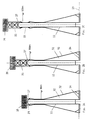
- Figs. 2A-2B-2C illustrate an embodiment of the invention which involves somewhat expanded possibilities of water depth variation compared to what is found in Fig. 1.
- Fig. 2A shows a configuration of a platform structure according to the invention, intended for smaller water depths, as indicted with the depth measure 85 m on this
- Fig. 2B shows a configuration intended for a medium water depth, indicated as a maximum of 105 m on that Fig.
- Fig. 2C shows a configuration of the platform structure for a maximum water depth, indicated as an example with the marking 125 m on this figure.
- FIGs. 2A, 2B and 2C the structures shown can be considered to constitute a platform system which has a high degree of flexibility for adaption to the water depth occurring at different offshore fields where it may be of interest to employ such platforms, and with possibilities of changing location within the same field or use at other fields normally via certain operations in quiet waters near the shore.
- Figs. 2A, 2B and 2C show main components which correspond to main components in Fig. 1, but the illustrations of Figs. 2A, 2B and 2C are somewhat more schematical and simplified, so that for example details of the joining means (9, 23 in Fig. 1) are not shown.
- Figs. 2A, 2B and 2C the seabed is indicated at 13, whereas 11 designates the concrete column and 14 designates the base part in all three configurations. Moreover, there are shown inclined walls 32 forming storage spaces 51 corresponding to respective elements 12 and 41 in Fig. 1.
- Fig. 2A shows a top unit 15 having a very low height, for supporting a module 16 being analogue to the module 6 in Fig. 1.
- a cover 17 which preferably constitutes an integral part of this top unit.
- the top unit 25 has a more "normal" height, similar to the one in Fig. 1, aiming at employment at a larger water depth.
- the top unit 25 carries a platform or deck module 26 and at a lower portion it is provided with a cover 27 for closing the concrete column 11 at the top.
- Fig. 2C the same top unit 25 is again found, but for employment at a still larger water depth there is here inserted another column part in the form of a hollow concrete cylinder 33 which can also be regarded as a more or less direct extension or upper portion of the concrete column 11 itself.
- the cover 27 at the lower end of the top unit 25 closes the upper open end of concrete cylinder 33.
- This concrete cylinder is provided with joining means at the top and bottom for joining with corresponding means as previously mentioned, on the top unit and the concrete column respectively.
- the top units 15 and 25 shown, in particular the latter, can be manufactured with various heights according to the requirements, and can advantageously be exchangeable in its entirety. In actual practice, however, it may be an advantageous method when exchanging such a top unit, to divide or cut the same at a level just above the cover 27, which means that the cover may be left in its position, joined to the upper end of the concrete column 11 or the concrete cylinder 33 as the case may be, with subsequent mounting of a new and possibly higher or lower top unit by welding, bolt connections or the like, so that the same lower portion with cover 27 is still used.
- 2A, 2B and 2C can be considered to constitute a platform system with main components in the form of a base part 14 with the associated column 11, a top unit or units 15 and 25 respectively, and a concrete cylinder 33 as shown in Fig. 2C.
- the top unit 25 and the concrete cylinder 33 contribute to a substantial degree to the flexibility and adaptability which is explained above.
- a re-usable platform structure whereby in operations at a field having the lowest water depth (Fig. 2A) there is employed a configuration having dimensions adapted to such water depth, and is closed at the upper end by means of a cover 17, whereby the top unit 15 directly supports a platform module 16.
- Fig. 2B When installed at a field having a moderate water depth (Fig. 2B) exceeding the above lowest water depth (Fig. 2A) there is employed a configuration having a larger height, whereby a top unit 25 with a cover 27 at its lower end supports a platform module 26.
- a maximum water depth Fig.
- the very concrete column 11 can be regarded as extended with the concrete cylinder 33 shown, which is open at both ends, and where the top unit 25 with its cover 27 in the first place closes the top of the concrete cylinder 33, and in the second place carries the module 26.
- This method of adapting the structure is made possible with a platform system as described above and illustrated in Figs. 2A, 2B and 2C, and which in a more simplified and principle form is illustrated in Fig. 1.
Landscapes
- Engineering & Computer Science (AREA)
- General Engineering & Computer Science (AREA)
- Mechanical Engineering (AREA)
- Civil Engineering (AREA)
- Structural Engineering (AREA)
- Foundations (AREA)
- Revetment (AREA)
- Earth Drilling (AREA)
Applications Claiming Priority (3)
| Application Number | Priority Date | Filing Date | Title |
|---|---|---|---|
| NO91912449A NO912449L (no) | 1991-06-24 | 1991-06-24 | Flyttbar plattform til havs. |
| NO912449 | 1991-06-24 | ||
| PCT/NO1992/000106 WO1993000482A1 (en) | 1991-06-24 | 1992-06-12 | Removable offshore platform |
Publications (2)
| Publication Number | Publication Date |
|---|---|
| EP0591298A1 EP0591298A1 (en) | 1994-04-13 |
| EP0591298B1 true EP0591298B1 (en) | 1996-02-14 |
Family
ID=19894246
Family Applications (1)
| Application Number | Title | Priority Date | Filing Date |
|---|---|---|---|
| EP92912735A Expired - Lifetime EP0591298B1 (en) | 1991-06-24 | 1992-06-12 | Removable offshore platform |
Country Status (4)
| Country | Link |
|---|---|
| EP (1) | EP0591298B1 (da) |
| DK (1) | DK0591298T3 (da) |
| NO (2) | NO912449L (da) |
| WO (1) | WO1993000482A1 (da) |
Families Citing this family (1)
| Publication number | Priority date | Publication date | Assignee | Title |
|---|---|---|---|---|
| GB2330854B (en) * | 1997-10-31 | 2002-04-17 | Ove Arup Partnership | Method of transporting and installing an offshore structure |
Family Cites Families (8)
| Publication number | Priority date | Publication date | Assignee | Title |
|---|---|---|---|---|
| US3824795A (en) * | 1971-03-16 | 1974-07-23 | Mo Och Domsjoe Ab | Platform structure |
| NL7409864A (nl) * | 1974-07-22 | 1976-01-26 | Panama Overseas Shipping Corp | Werkwijze ter vervaardiging van een kunstmatig eiland; alsmede kunstmatig eiland bestemd voor toepassing bij de werkwijze. |
| FR2305547A1 (fr) * | 1975-03-26 | 1976-10-22 | Sea Tank Co | Procede d'immersion d'une structure-poids off-shore a deux compartiments |
| NO144711C (no) * | 1978-04-04 | 1981-10-21 | Myrens Verksted As | Fremgangsmaate til bleking av oksygendelignifiserte celluloseholdige masser med ozon |
| GB2034789B (en) * | 1978-11-23 | 1982-12-01 | Williams & Partners Sir Owen | Offshore structure |
| FI89516B (fi) * | 1989-05-10 | 1993-06-30 | Ahlstroem Oy | Foerfarande foer blekning av cellulosamassa med otson |
| AU636173B2 (en) * | 1989-10-30 | 1993-04-22 | Lenzing Aktiengesellschaft | Method for the chlorine-free bleaching of pulps |
| AT393701B (de) * | 1989-12-22 | 1991-12-10 | Schmidding Wilh Gmbh & Co | Verfahren zum bleichen von cellulosehaeltigen materialien sowie anlage zur durchfuehrung des verfahrens |
-
1991
- 1991-06-24 NO NO91912449A patent/NO912449L/no unknown
-
1992
- 1992-06-12 EP EP92912735A patent/EP0591298B1/en not_active Expired - Lifetime
- 1992-06-12 WO PCT/NO1992/000106 patent/WO1993000482A1/en not_active Ceased
- 1992-06-12 DK DK92912735.5T patent/DK0591298T3/da active
-
1993
- 1993-12-23 NO NO934814A patent/NO934814D0/no unknown
Also Published As
| Publication number | Publication date |
|---|---|
| NO934814L (no) | 1993-12-23 |
| WO1993000482A1 (en) | 1993-01-07 |
| EP0591298A1 (en) | 1994-04-13 |
| DK0591298T3 (da) | 1996-03-11 |
| NO912449L (no) | 1992-12-28 |
| NO934814D0 (no) | 1993-12-23 |
| NO912449D0 (no) | 1991-06-24 |
Similar Documents
| Publication | Publication Date | Title |
|---|---|---|
| US4161376A (en) | Offshore fixed platform and method of erecting the same | |
| US4618286A (en) | Composite platform for petroleum workings in polar seas | |
| FI92234C (fi) | Tuotantojärjestelmä vesialueen pohjaan porattuja öljylähteitä varten | |
| US4266887A (en) | Self-elevating fixed platform | |
| US4566824A (en) | System for drilling from a water surface, which is insensitive to the swell | |
| NO145444B (no) | Fremgangsmaate til bygging av dekkskonstruksjon og utfoerelse av samme. | |
| NO20160906A1 (en) | Sea bed terminal for drilling | |
| WO2003093584A1 (en) | Method and vessel for manipulating an offshore construction | |
| SU1553016A3 (ru) | Морска платформа | |
| AU7220481A (en) | Offshore platform | |
| WO2002092425A1 (en) | Floating multipurpose platform structure and method for constructing same | |
| GB2225365A (en) | Building and installing offshore gravity platforms | |
| RU2129638C1 (ru) | Морские платформы для поддерживания самоподнимающихся установок | |
| EP0795648A3 (en) | Offshore production platform | |
| RU95113879A (ru) | Морские платформы для поддерживания самоподнимающихся установок | |
| US4187038A (en) | Equipment for extracting oil or gas from under the sea bed and method of installing such equipment | |
| EP0591298B1 (en) | Removable offshore platform | |
| CA1242082A (en) | Deep water mobile submersible arctic structure | |
| EP1425476B1 (en) | Offshore structure support | |
| GB2041836A (en) | Drilling Vessels | |
| RU2139220C1 (ru) | Установка и способ для обеспечения буровых работ в открытом море | |
| US4114392A (en) | Platform structure for maritime installations | |
| RU2036268C1 (ru) | Способ монтажа морской ледостойкой платформы и устройство для его осуществления | |
| GB1523585A (en) | Offshore platforms | |
| SU1749374A1 (ru) | Передвижна морска платформа и способ ее монтажа и демонтажа |
Legal Events
| Date | Code | Title | Description |
|---|---|---|---|
| PUAI | Public reference made under article 153(3) epc to a published international application that has entered the european phase |
Free format text: ORIGINAL CODE: 0009012 |
|
| 17P | Request for examination filed |
Effective date: 19931223 |
|
| AK | Designated contracting states |
Kind code of ref document: A1 Designated state(s): DK GB NL |
|
| 17Q | First examination report despatched |
Effective date: 19950403 |
|
| GRAA | (expected) grant |
Free format text: ORIGINAL CODE: 0009210 |
|
| AK | Designated contracting states |
Kind code of ref document: B1 Designated state(s): DK GB NL |
|
| REG | Reference to a national code |
Ref country code: DK Ref legal event code: T3 |
|
| PLBE | No opposition filed within time limit |
Free format text: ORIGINAL CODE: 0009261 |
|
| STAA | Information on the status of an ep patent application or granted ep patent |
Free format text: STATUS: NO OPPOSITION FILED WITHIN TIME LIMIT |
|
| 26N | No opposition filed | ||
| PGFP | Annual fee paid to national office [announced via postgrant information from national office to epo] |
Ref country code: GB Payment date: 19980603 Year of fee payment: 7 |
|
| PGFP | Annual fee paid to national office [announced via postgrant information from national office to epo] |
Ref country code: DK Payment date: 19980612 Year of fee payment: 7 |
|
| PGFP | Annual fee paid to national office [announced via postgrant information from national office to epo] |
Ref country code: NL Payment date: 19980629 Year of fee payment: 7 |
|
| PG25 | Lapsed in a contracting state [announced via postgrant information from national office to epo] |
Ref country code: GB Free format text: LAPSE BECAUSE OF NON-PAYMENT OF DUE FEES Effective date: 19990612 Ref country code: DK Free format text: LAPSE BECAUSE OF NON-PAYMENT OF DUE FEES Effective date: 19990612 |
|
| PG25 | Lapsed in a contracting state [announced via postgrant information from national office to epo] |
Ref country code: NL Free format text: LAPSE BECAUSE OF NON-PAYMENT OF DUE FEES Effective date: 20000101 |
|
| GBPC | Gb: european patent ceased through non-payment of renewal fee |
Effective date: 19990612 |
|
| NLV4 | Nl: lapsed or anulled due to non-payment of the annual fee |
Effective date: 20000101 |
|
| REG | Reference to a national code |
Ref country code: DK Ref legal event code: EBP |