EP0591366B1 - Systeme de commande automatique de gain pour stabilisateur de bateau - Google Patents
Systeme de commande automatique de gain pour stabilisateur de bateau Download PDFInfo
- Publication number
- EP0591366B1 EP0591366B1 EP92913819A EP92913819A EP0591366B1 EP 0591366 B1 EP0591366 B1 EP 0591366B1 EP 92913819 A EP92913819 A EP 92913819A EP 92913819 A EP92913819 A EP 92913819A EP 0591366 B1 EP0591366 B1 EP 0591366B1
- Authority
- EP
- European Patent Office
- Prior art keywords
- motion
- signal
- vessel
- stabilising
- gain
- Prior art date
- Legal status (The legal status is an assumption and is not a legal conclusion. Google has not performed a legal analysis and makes no representation as to the accuracy of the status listed.)
- Revoked
Links
- 239000003381 stabilizer Substances 0.000 title claims abstract description 17
- 230000033001 locomotion Effects 0.000 claims abstract description 92
- 230000003019 stabilising effect Effects 0.000 claims description 37
- 230000006641 stabilisation Effects 0.000 claims description 12
- 238000012545 processing Methods 0.000 claims description 10
- 238000000034 method Methods 0.000 claims description 6
- 238000013461 design Methods 0.000 claims description 4
- 238000009434 installation Methods 0.000 claims description 3
- 238000011065 in-situ storage Methods 0.000 claims description 2
- 238000001914 filtration Methods 0.000 claims 1
- 230000000694 effects Effects 0.000 abstract description 9
- 238000010586 diagram Methods 0.000 description 11
- 238000005259 measurement Methods 0.000 description 7
- 230000001133 acceleration Effects 0.000 description 4
- 230000008901 benefit Effects 0.000 description 4
- 230000009467 reduction Effects 0.000 description 4
- 230000004044 response Effects 0.000 description 4
- 238000012935 Averaging Methods 0.000 description 2
- 230000008878 coupling Effects 0.000 description 2
- 238000010168 coupling process Methods 0.000 description 2
- 238000005859 coupling reaction Methods 0.000 description 2
- 230000007423 decrease Effects 0.000 description 2
- 235000010627 Phaseolus vulgaris Nutrition 0.000 description 1
- 244000046052 Phaseolus vulgaris Species 0.000 description 1
- 230000006978 adaptation Effects 0.000 description 1
- 230000002411 adverse Effects 0.000 description 1
- 230000004075 alteration Effects 0.000 description 1
- 238000010276 construction Methods 0.000 description 1
- 230000001934 delay Effects 0.000 description 1
- 230000003111 delayed effect Effects 0.000 description 1
- 230000003993 interaction Effects 0.000 description 1
- 238000012986 modification Methods 0.000 description 1
- 230000004048 modification Effects 0.000 description 1
- 238000012544 monitoring process Methods 0.000 description 1
- 201000003152 motion sickness Diseases 0.000 description 1
- 230000008569 process Effects 0.000 description 1
- 229920006395 saturated elastomer Polymers 0.000 description 1
Images




Classifications
-
- B—PERFORMING OPERATIONS; TRANSPORTING
- B63—SHIPS OR OTHER WATERBORNE VESSELS; RELATED EQUIPMENT
- B63B—SHIPS OR OTHER WATERBORNE VESSELS; EQUIPMENT FOR SHIPPING
- B63B39/00—Equipment to decrease pitch, roll, or like unwanted vessel movements; Apparatus for indicating vessel attitude
- B63B39/06—Equipment to decrease pitch, roll, or like unwanted vessel movements; Apparatus for indicating vessel attitude to decrease vessel movements by using foils acting on ambient water
-
- G—PHYSICS
- G05—CONTROLLING; REGULATING
- G05D—SYSTEMS FOR CONTROLLING OR REGULATING NON-ELECTRIC VARIABLES
- G05D1/00—Control of position, course, altitude or attitude of land, water, air or space vehicles, e.g. using automatic pilots
- G05D1/08—Control of attitude, i.e. control of roll, pitch, or yaw
- G05D1/0875—Control of attitude, i.e. control of roll, pitch, or yaw specially adapted to water vehicles
Definitions
- the present invention relates to a system for stabilising the movement of ships or floating vessels.
- the invention relates to a fin stabiliser control system for use with ships.
- a fin stabiliser control system is used to control stabilisers of a ship in order to reduce ship motions.
- fins and their associated actuation systems exhibit two major non-linearities; slew rate limiting and fin-angle limiting.
- the first non-linearity; slew rate limiting occurs because the actuation systems are only capable of driving the fins up to some finite rate. This rate may vary with the fin angle.
- the second occurs if the fin is operated above a certain angle, when "stalling" of the fin occurs.
- the first way is to ensure that the maximum slew rate of the fin is such that the phase delays introduced for all reasonable disturbances are low enough not to matter. This has the advantage of simplicity, but the disadvantage at the drive system must be powerful enough, and provide sufficient torque, to provide the requisite slew rates.
- the second way is to reduce the controller loop gain so that the fin slew rate is never exceeded and the nose-up and nose-down limits are never reached.
- the control gain is reduced, the non-saturated roll reduction reduces as well.
- the principal advantage is that the drive system, power and torque capability may be reduced considerably when compared with the first potential solution.
- the main points to consider are the relative fall off in performance in the two types of potential solution with increase in disturbances for a given drive system power and torque capabilities, and also the trade off between performance and cost. In this regard, it is desirable to reduce the cost of the drive system whilst not comprising the roll reduction achieved.
- An object of the present invention is to provide an improved fin stabiliser control system which obviates or mitigates at least one of the aforementioned disadvantages.
- control laws can be prioritised and the available actuator power thus rationed.
- the automatic gain control (AGC) sub-system of the control law monitors the motions of the fins and detects when each fin is not following the control law demands. It adjusts the gain of the control law so as to reduce the slew rate limit and the fin angle limit effects.
- a control law is a physical realisation of a mathematical equation which continuously generates actuater demands in response to error inputs in order to achieve the desired motion or position characteristics of an object, in this case the fin or fins.
- the control law may be identical in structure to current control laws or of a different structure provided that it can accommodate changes to the loop gain.
- the automatic gain control (AGC) sub-system has the effect of reducing the control law loop gain, it reduces the ship motions below those achieved with a conventional control law because the phase lag between the demanded and actual fin angles is reduced and because generation of harmonics of the demanded fin angle is much reduced.
- the AGC sub-system solves the two basic problems. It firstly measures the level of slew rate limiting and/or fin angle limiting by subtracting the demanded fin angle from the actual fin angle and the absolute value of the result is compared with the corresponding absolute values calculated from all other fins in the stabilisation system, and the largest of these values is selected and filtered to produce an overload measurement.
- the filter used may have different "attack” and "decay” times. Therefore, if an overload occurs it may cause a rapid increase in the overload measurement, while if such an overload is removed the return to lower overload measurements is much slower. This prevents overload from being present for long periods wile preventing rapid modulations of control law gain.
- the overload measurement is then converted to a gain which is varied from some maximum (for no overload), to a selectible minimum (for large overloads).
- the minimum is set to a suitable value (for example 30% of the maximum) so that the control law gain is not excessively reduced and the slope of the gain against overload is made variable to allow the AGC sub-system to be tuned for a particular configuration.
- the control law fin angle demand is then multiplied by the gain value calculated above to derive the actual fin angle demand.
- the instantaneous power consumption is proportional at high slew rates to the square of the slew rate.
- the AGC controller can reduce the average power consumption by reducing the amount of time the fin operates at high slew rates.
- the AGC controller can be used with lower slew rate fins. This slew rate can be selected to provide the same performance levels as current fins with conventional controllers, but with much lower average and peak power consumption.
- a vessel motion stabilisation system for stabilising at least one motion of a vessel having a plurality of actuatable vessel stabilising elements, according to claim 1.
- said automatic gain control means includes absolute error detecting means for determining the absolute error between the stabiliser demand signal and the actual stabiliser signal, and filter means coupled to the output of the absolute error detecting means to provide a filtered response loop gain control means for receiving the output of the filter means for limiting the loop gain of the control unit to a value between a maximum and a minimum.
- the vessel is a ship and the vessel stabilising elements are fins which are hydraulically or electrically actuatable.
- the fin motion detecting elements are preferably accelerometers, rate sensors or angle sensors, and the motion controlled is the roll notion of the ship.
- said loop gain control means limits the maximum demand angle to a pre-determined value, for example, plus or minus 25°.
- a vessel stabilising system for stabilising the motion of a vessel, the vessel having a plurality of vessel notions to be controlled simultaneously, according to claim 6.
- the vessel is a ship and the vessel stabilising elements are fins.
- the vessel stabilising elements are fins.
- An accelerometer or other motion sensor provides the motion signal from each controlled motion.
- the motion signals are weighted in accordance with control laws for each motion which depend on the vessel and installation-specific criteria. Weighting is achieved by constants which are set at the design stage. The constants can be changed in-situ to meet changing performance requirements.
- the maximum is 1.0 and the minimum is zero.
- the method includes controlling a plurality of vessel motions by monitoring signals representative of the motions of each stabilising element, according to claim 14.
- Figs. 1 and 2 of the drawings depicts a plan view of a SWATH, generally indicated by reference numeral 10, which has four identical moveable fins 12, 14, 16 and 18 located on the hull as shown.
- reference numeral 10 depicts a plan view of a SWATH, generally indicated by reference numeral 10, which has four identical moveable fins 12, 14, 16 and 18 located on the hull as shown.
- control is applicable to all fins in an identical manner using the automatic gain control system of the present invention.
- Roll control is discussed initially to simplify understanding and the heave and pitch control is discussed in the fin stabilisation system.
- Fig. 3 of the drawings is a block diagram of the roll control law for processing a vector of ship roll angle, roll velocity and roll acceleration to produce a fin angle demand.
- the roll control law will vary from vessel to vessel,but in its simplest form may be represented by velocity multiplied by a constant and implemented in hardware or software. It will be understood that in practice one or more of these components may be absent.
- the vector, ⁇ v , of ship roll acceleration velocity and angle is fed to the roll control unit 20 which is implemented in software.
- the output, ⁇ D , of the unit 20 is fed to a multiplier 22 which is also implemented in software which multiplies ⁇ D by the gain value ⁇ G , as will be described.
- the output of multiplier 22, the roll control law fin angle demand F D is fed to the automatic gain control (AGC) 24 and to a limit block 26, also implemented in software, which limits the fin angle demand F D to maximum working angle of the fin (e.g. 25°), designated F DL , before being fed to the fin service system (not shown) which continuously attempts to place the fin at the demanded fin angle.
- AGC automatic gain control
- F DL maximum working angle of the fin
- the actual fin angle demand F DL is a scaled version of the roll control law angle demand F D with the scaling factor being determined by the AGC unit 24.
- Fig. 4 of the drawings depicts the AGC unit 24 which monitors the difference between the unlimited fin angle F D demand and the actual fin angle F A .
- the actual value F A is subtracted from the fin angle demand F D to provide an error value. If the actual fin angle F A limits or if the slew rate limiting occurs, then the error will increase.
- the absolute value of this value is taken by block 28, which is implemented in software, so that the sense of the error does not matter.
- the resulting absolute value is filtered in filter 30 so that the bandwidth of the control law gain adjustment can be tailored.
- Filter 30 consists of a filter loop having an AGC filter time constant unit 32 over an integrator 34.
- the time constant unit 32 has two time constants to provide a time-averaging asymmetric response to ensure that AGC operation is smoothed. Normally this bandwidth is considerably smaller than the control law bandwidth.
- the filtered value is a measure of the overload experienced by the fin and its actuation system over the last few cycles of operation.
- the filter 30 is implemented in software.
- the overload measurement is then multiplied by a gain K agc in software-implemented gain unit 36 which is used to tailor the loop gain of the AGC sub-system.
- the loop gain is then limited in a software-implemented limit unit 38 to between a minimum (0.0) and a maximum (1.0) and subtracted from 1.0 by the summation system indicated.
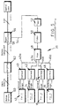
- Fig. 5 of the drawings depicts a block diagram of an automatic gain controller 39 for use in a system where the 4 fins (actuators) of the Swath are analysed to derive the gains for 3 control laws to control roll, pitch and heave motions.
- the fins operate as opposed pairs to reduce the roll, pitch and heave.
- the AGC controller shown in Fig. 5 includes enhancements over those shown in Figs. 3 and 4 to allow for individual selection of control laws and to cater for particular fins being unavailable.
- the AGC system shown in Fig. 5 uses the difference between the control laws demand and the actual fin angles as described with reference to Figs. 3 and 4 to calculate multiple gain factors to reduce the total control laws demand until the non-linearities almost disappear as will be described. If more than one control law is generating the demand, then the demands can be prioritised and the available actuator power can be rationed accordingly.
- FIG. 5 shows two logical halves: the lower half generates a single gain reduction factor K agc based on the fin position errors, and the upper half allocates fin power between the 3 control laws according to the weighted Swath vessel motions, as will be later described in detail.
- Each fin 10, 12, 14 and 16 produces a demand and an angle which is fed to a respective overload unit 40, 42, 44, 46 one of which is seen in Fig. 6.
- Each overload unit is implemented in software and subtracts the actual fin position from the desired position and passes the difference through a deadband unit 47 which sets the difference to zero if it is less than a predetermined deadband value (which is set depending on the application). This has the advantage in that it allows for transducer calibration errors. Once this has been achieved the absolute value of the difference is taken by block 49, i.e. the sign is discarded.
- the outputs 40a, 42a, 44a and 46a of each of the overload units is fed to a software-implemented block 48 designated MAX which compares all of the error outputs of the overload blocks and then selects the largest absolute error. This is so that the AGC 39 always reacts to the worst case.
- the largest error selected is fed to a filter 50 has a time constant unit 51 with two time constants similar to unit 32 and an integrator 53 which provides a time-averaging asymmetric (that is, a fast attack and slow decay) response to the ensure that the AGC operation is smoothed.
- the output of the filter 50 Is fed to the gain unit 52 K agc of the AGC gain controller. The value of K is chosen so that the greatest possible actuator error is converted to unity.
- the output of gain unit 52 varies in time from zero, when all of the fins are correctly responding to the control law demands, to 1.0 which occurs when one or more of the fins is at one end of its travel and the control law expects it to be at the other end.
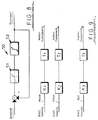
- the output 54 from the gain unit 52 is fed to the power allocation block 56 which is best seen in Fig. 10.
- the power allocation block 56 also receives another input 58, the three motion components, which originates from the motion sensors 60 which are accelerometers.
- the accelerometers provide signals which are integrated to give a time-averaged value (RMS) of velocity or other estimate of the relevant motion and the averaged values are fed to the weighting unit, generally indicated by reference numeral 62.
- RMS time-averaged value
- the output of the weighting block generates three weighted motion components corresponding to roll, pitch and heave . These weighted components are fed to the power allocator shown in Fig. 10.
- the constants K,T are software-implemented and are set at the design stage, but can be varied on-site to suit particular sea or vessel requirements.
- the power allocator 56 receives all three of the weighted motion components which are summed in unit 64 to generate a total value which passed to each of three motion gain calculators 66a, b and c.
- the motion gain calculators 66a, b and c also receive the same overload signal, and each receives its respective motion component. This means that, for example, gain calculator 66a receives motion component 1, the total of the weighted motion components and the overload signal.
- Each motion gain calculator 66a, b and c is identical and one 66a will be now be described with reference to Fig. 11. It is software-implemented and processes the three input signals by dividing the sum total by the motion component and then multiplying the output result 68 by the overload signal. The result of this multiplication is limited to 1 in a limit unit 70 and, as shown in Fig. 4, and the result is then subtracted from 1.0 to produce a particular AGC motion gain value 72. This is repeated for each motion gain calculator.
- the AGC sub-system of the control law monitors the motions of the fin and detects when the fin is not following the control law demands. It then adjusts the gain, by reducing it to a level that the fin can achieve, of the control law so as to reduce the slew rate limit and fin angle limit effects.
- the control law may be identical in structure to current control laws or of a different structure provided it can cope with having its loop gain changed from time to time.
- the AGC controller may be used for controlling a plurality of motions, i.e. more than 3 or 4 degress of freedom.
- sensors may be used instead of accelerometers, for example, velocity sensors and the motions sensed may be linear or angular.
- the system is described as being implemented in software, this is a preferred arrangement and it will be understood that the units hereinbefore described can also be implemented in hardware by a person of ordinary skill in the art.
- the system and apparatus hereinbefore described may be incorporated in a vessel during construction or it may be retrofitted to existing vessels.
- the AGO controller may be interfaced with existing vessel control system if the vessel control law used is capable of accepting a variable gain.
- An advantage of the present invention is that the AGC controller allows a stabilisation system designer to trade off performance against power consumption. It can provide better performance in rough weather than a conventional controller using the same drive system or it can provide the same performance with a smaller drive system.
- the AGC controller can easily be extended to allow multiple control loops to use the same set of stabilisers with much reduced inter-loop interference compared with fixed gain controllers. This increases the performance of the control loop.
- the AGC controller allows available stabilisation capacity to be allocated between multiple control loops to try to maximise overall stabilisation according to some pre-set criterion.
- the AGC controller has applicability to stabilisation systems in a variety of ship and floating vessel designs, and although the AGC sub-system has the effect of reducing the control loop gain it actually reduces the ship or vessel motions below those achieved with the conventional control law because the phase lag between the demanded and the actual fin angles is reduced and because the generation of the harmonics of the demanded fin angle is also much reduced.
Landscapes
- Engineering & Computer Science (AREA)
- Radar, Positioning & Navigation (AREA)
- Combustion & Propulsion (AREA)
- Mechanical Engineering (AREA)
- Ocean & Marine Engineering (AREA)
- Aviation & Aerospace Engineering (AREA)
- Chemical & Material Sciences (AREA)
- Remote Sensing (AREA)
- Physics & Mathematics (AREA)
- General Physics & Mathematics (AREA)
- Automation & Control Theory (AREA)
- Feedback Control In General (AREA)
- Control Of Position, Course, Altitude, Or Attitude Of Moving Bodies (AREA)
Abstract
Claims (14)
- Système de stabilisation de mouvement de vaisseau pour stabiliser au moins un mouvement d'un vaisseau comportant une pluralité d'éléments de stabilisation de vaisseau activables, ledit système de stabilisation comprenant:un moyen de détection de mouvement pour générer un signal (φV) représentatif du mouvement de vaisseau à stabiliser;un moyen de règle de commande (20) pour recevoir le signal de mouvement (φV) et pour traiter le signal de mouvement afin de produire un signal de demande d'élément de stabilisation non limitée (φD) ;un moyen de commande automatique de gain (24) pour produire un signal de commande automatique de gain (φG); etun moyen (22) pour combiner le signal de commande de gain (φG) avec le signal de demande non limitée (φD) pour produire un signal de demande réelle (FDL) pour commander le mouvement desdits éléments de stabilisation de mouvement,caractérisé en ce que le moyen de commande automatique de gain (24) est agencé pour recevoir un signal (FD) représentatif dudit signal de demande de règle de commande non limitée et un signal (FA) représentatif de la condition d'élément de stabilisation réelle, le moyen de commande automatique de gain (24) incluant un moyen pour comparer le signal de demande non limitée (FD) au signal (FA) représentatif de la condition d'élément de stabilisation réelle et pour produire une valeur d'erreur, et un moyen de traitement de signal pour traiter ladite valeur d'erreur afin de produire ledit signal de commande automatique de gain (φG).
- Système selon la revendication 1, dans lequel le moyen de commande automatique de gain (24) inclut un moyen de détection d'erreur absolue (28) pour déterminer l'erreur absolue entre le signal de demande de stabiliseur (FD) et le signal (FA) représentatif de la condition d'élément de stabilisation réelle, un moyen de filtre (30) ayant son entrée couplée à la sortie du moyen de détection d'erreur absolue (28) et comportant une boucle de retour depuis la sortie de filtre jusqu'à l'entrée de filtre, un moyen de gain de filtre (36) couplé à la sortie de filtre pour produire une valeur de gain de filtre et un moyen de limitation de gain (38) couplé à la sortie du moyen de gain de filtre (36) pour limiter le gain de boucle à une valeur entre un maximum et un minimum.
- Système selon la revendication 1 ou 2, dans lequel le vaisseau est un bateau et les éléments de stabilisation de vaisseau sont des ailettes (12, 14, 16, 18) qui peuvent être actionnées hydrauliquement ou électriquement.
- Système selon la revendication 3, dans lequel les éléments de détection de mouvement d'ailette sont des accéléromètres, des capteurs de vitesse ou des capteurs d'angle et le mouvement commandé est le mouvement de roulis du bateau.
- Système selon l'une quelconque des revendications 2 à 4, dans lequel le moyen de limitation de gain (38) limite l'angle de demande maximum à une valeur prédéterminée, par exemple plus ou moins 25°.
- Système de stabilisation de vaisseau pour stabiliser le mouvement d'un vaisseau, le vaisseau présentant une pluralité de mouvements de vaisseau à commander simultanément, et le vaisseau comportant une pluralité d'éléments de stabilisation de vaisseau actionnables, le système de stabilisation comprenant pour chaque élément de stabilisation de vaisseau:un moyen de détection de position ou de mouvement (60) pour générer un signal représentatif de la position ou du mouvement de l'élément de stabilisation;un moyen de règle de commande pour générer un signal de demande d'élément de stabilisation non limitée en fonction du signal de mouvement ou de position; etun moyen de détection d'erreur (40) agencé pour recevoir lesdits signaux de demande et lesdits signaux représentatifs de la condition d'élément de stabilisation réelle et pour produire un signal d'erreur;le système de stabilisation comprenant en outre:un moyen de pondération de signal (62) couplé au moyen de détection de mouvement (60) pour recevoir les signaux de sortie représentatifs de la position ou du mouvement des éléments de stabilisation, le moyen de pondération (62) incluant un moyen pour générer des composantes de mouvement de vaisseau pondérées pour pondérer la proportion de puissance disponible à établir pour un moyen de règle de commande de mouvement de vaisseau particulier conformément à des critères prédéterminés;un moyen de comparaison de signal d'erreur (48) couplé à chacun des moyens de détection d'erreur pour recevoir lesdits signaux d'erreur et pour sélectionner le signal d'erreur le plus grand en tant que signal de sortie;un moyen de traitement de signal de sortie (50, 52) pour filtrer et amplifier ledit signal de sortie afin de produire une valeur de gain entre un maximum et un minimum; etun moyen d'allocation de puissance (56) couplé aux sorties du moyen de pondération (62) et du moyen de traitement de signal (50, 52) pour recevoir lesdites composantes de mouvement de vaisseau pondérées et ladite valeur de gain, le moyen d'allocation de puissance (56) incluant un moyen de sommation (64) pour sommer lesdites composantes de mouvement de vaisseau pondérées pour produire une valeur totale, et une pluralité de moyens de calcul de gain de mouvement de vaisseau (66) pour déterminer des gains de mouvement de vaisseau respectifs, lesdits moyens de calcul de gain (66) recevant ladite valeur totale des composantes pondérées, la composante pondérée pour un mouvement particulier et la valeur de gain produite par le moyen de traitement de signal (50, 52), chaque moyen de calcul de gain (66) produisant une valeur de gain de mouvement qui est appliquée sur un moyen pour piloter lesdits éléments de stabilisation de mouvement.
- Système selon la revendication 6, dans lequel le vaisseau est un bateau et les éléments de stabilisation de vaisseau sont des ailettes.
- Système selon la revendication 7, dans lequel il y a quatre ailettes et trois règles de commande.
- Système selon l'une quelconque des revendications 6 à 8, dans lequel un accéléromètre ou tout autre capteur de mouvement produit le signal de mouvement pour chaque mouvement commandé.
- Système selon l'une quelconque des revendications 6 à 9, dans lequel les signaux de mouvement sont pondérés conformément à des règles de commande pour chaque mouvement qui dépendent du vaisseau et de critères spécifiques à l'installation.
- Système selon la revendication 10, dans lequel une pondération est réalisée au moyen de constantes qui sont établies lors de l'étape de conception, lesdites constantes pouvant être altérées in situ pour satisfaire des exigences de performances variables.
- Système selon l'une quelconque des revendications 6 à 11, dans lequel la valeur de gain maximum vaut 1,0 et son minimum vaut zéro.
- Procédé de stabilisation d'au moins un mouvement d'un vaisseau comportant une pluralité d'éléments de stabilisation de vaisseau actionnables, le procédé comprenant les étapes de:détection dudit au moins un mouvement et production d'un signal représentatif du mouvement;traitement du signal représentatif du mouvement pour produire un signal de demande d'élément de stabilisation non limitée;production d'un signal de commande automatique de gain; etcombinaison du signal de commande de gain avec le signal de demande non limitée pour produire un signal de demande réelle pour commander le mouvement des éléments de stabilisation,caractérisé en ce que l'étape de production du signal de commande de gain comprend la réception d'un signal représentatif du signal de demande de règle de commande non limitée et d'un signal représentatif de la condition d'élément de stabilisation réelle, la comparaison des signaux reçus pour produire un signal d'erreur et le traitement du signal d'erreur pour produire le signal de commande automatique de gain.
- Procédé selon la revendication 13 pour stabiliser une pluralité de mouvements de vaisseau et comprenant la détection de chacun des mouvements pour produire des signaux correspondants représentatifs des mouvements, l'étape de traitement comprenant la génération, à partir des signaux représentatifs des mouvements, de valeurs de gain pondérées.
Applications Claiming Priority (3)
| Application Number | Priority Date | Filing Date | Title |
|---|---|---|---|
| GB91137844 | 1991-06-26 | ||
| GB919113784A GB9113784D0 (en) | 1991-06-26 | 1991-06-26 | Ship stabiliser automatic gain control system |
| PCT/GB1992/001139 WO1993000255A2 (fr) | 1991-06-26 | 1992-06-24 | Systeme de commande automatique de gain pour stabilisateur de bateau |
Publications (2)
| Publication Number | Publication Date |
|---|---|
| EP0591366A1 EP0591366A1 (fr) | 1994-04-13 |
| EP0591366B1 true EP0591366B1 (fr) | 1996-10-09 |
Family
ID=10697347
Family Applications (1)
| Application Number | Title | Priority Date | Filing Date |
|---|---|---|---|
| EP92913819A Revoked EP0591366B1 (fr) | 1991-06-26 | 1992-06-24 | Systeme de commande automatique de gain pour stabilisateur de bateau |
Country Status (6)
| Country | Link |
|---|---|
| US (1) | US5452674A (fr) |
| EP (1) | EP0591366B1 (fr) |
| JP (1) | JPH06508584A (fr) |
| DE (1) | DE69214452D1 (fr) |
| GB (1) | GB9113784D0 (fr) |
| WO (1) | WO1993000255A2 (fr) |
Cited By (3)
| Publication number | Priority date | Publication date | Assignee | Title |
|---|---|---|---|---|
| WO1999036195A1 (fr) | 1998-01-15 | 1999-07-22 | Siemens Aktiengesellschaft | Procede de commande d'un dispositif servant au retrait d'envois plats d'une pile |
| US6240869B1 (en) | 1997-07-25 | 2001-06-05 | Benny Gaber | Watercraft stabilization apparatus |
| US6367400B1 (en) | 1998-01-22 | 2002-04-09 | Siemens Aktiengesellschaft | Stabilization apparatus for ship movement |
Families Citing this family (9)
| Publication number | Priority date | Publication date | Assignee | Title |
|---|---|---|---|---|
| CN1042512C (zh) * | 1993-01-12 | 1999-03-17 | 上海华禹科技开发公司 | 水翼船平稳紧急降落系统 |
| AU687029B2 (en) * | 1994-01-10 | 1998-02-19 | Kvaerner Fjellstrand A/S | Device for reduction of wave-induced motion of a vessel |
| US6836707B2 (en) * | 2002-05-30 | 2004-12-28 | Honeywell International Inc. | Methods and systems for determining heave and heave rate of vessels |
| GB0427659D0 (en) * | 2004-12-17 | 2005-01-19 | Delta T Devices Ltd | Moisture content sensor and related methods |
| GB0703128D0 (en) * | 2007-02-16 | 2007-03-28 | Rolls Royce Plc | Stall detection |
| WO2011100796A1 (fr) | 2010-02-17 | 2011-08-25 | Halcyon International Pty Ltd | Système de commande de gyrostablisateur adaptatif actif |
| CN109018237B (zh) * | 2018-06-19 | 2020-09-25 | 哈尔滨工程大学 | 一种船舶鳍/水舱联合减横摇智能控制系统及其控制方法 |
| CN114802594B (zh) * | 2022-06-02 | 2022-10-18 | 哈尔滨理工大学 | 一种升沉补偿的三自由度船载稳定平台 |
| EP4484272B1 (fr) * | 2023-06-27 | 2026-02-25 | Humphree AB | Système informatique conçu pour actionner un stabilisateur de mouvement de pas |
Family Cites Families (3)
| Publication number | Priority date | Publication date | Assignee | Title |
|---|---|---|---|---|
| US3727572A (en) * | 1971-10-22 | 1973-04-17 | Sperry Rand Corp | Marine fin stabilizer control circuit |
| US4380206A (en) * | 1981-03-25 | 1983-04-19 | The United States Of America As Represented By The Secretary Of The Navy | Ship roll stabilization system |
| NL8302077A (nl) * | 1983-06-10 | 1985-01-02 | Rietschoten & Houwens Elek | Regelstelsel. |
-
1991
- 1991-06-26 GB GB919113784A patent/GB9113784D0/en active Pending
-
1992
- 1992-06-24 US US08/167,904 patent/US5452674A/en not_active Expired - Fee Related
- 1992-06-24 WO PCT/GB1992/001139 patent/WO1993000255A2/fr not_active Ceased
- 1992-06-24 DE DE69214452T patent/DE69214452D1/de not_active Expired - Lifetime
- 1992-06-24 JP JP5501398A patent/JPH06508584A/ja not_active Ceased
- 1992-06-24 EP EP92913819A patent/EP0591366B1/fr not_active Revoked
Cited By (3)
| Publication number | Priority date | Publication date | Assignee | Title |
|---|---|---|---|---|
| US6240869B1 (en) | 1997-07-25 | 2001-06-05 | Benny Gaber | Watercraft stabilization apparatus |
| WO1999036195A1 (fr) | 1998-01-15 | 1999-07-22 | Siemens Aktiengesellschaft | Procede de commande d'un dispositif servant au retrait d'envois plats d'une pile |
| US6367400B1 (en) | 1998-01-22 | 2002-04-09 | Siemens Aktiengesellschaft | Stabilization apparatus for ship movement |
Also Published As
| Publication number | Publication date |
|---|---|
| GB9113784D0 (en) | 1991-11-06 |
| WO1993000255A2 (fr) | 1993-01-07 |
| WO1993000255A3 (fr) | 1993-02-18 |
| EP0591366A1 (fr) | 1994-04-13 |
| US5452674A (en) | 1995-09-26 |
| JPH06508584A (ja) | 1994-09-29 |
| DE69214452D1 (de) | 1996-11-14 |
Similar Documents
| Publication | Publication Date | Title |
|---|---|---|
| US5452674A (en) | Ship stabiliser automatic gain control system | |
| US5571953A (en) | Method and apparatus for the linear real time estimation of an aircraft center of gravity | |
| US8904948B2 (en) | Fault tolerant vessel stabiliser control system | |
| EP0139277B1 (fr) | Système de commande pour transmission à rapport de vitesse continuellement variable | |
| CA1090906A (fr) | Bloc de pilotage adapte aux navires | |
| EP0389192B1 (fr) | Appareil de stabilisation de fluctuation | |
| US6564110B1 (en) | Position controlling apparatus capable of reducing the effect of disturbance | |
| Perez et al. | Model predictive rudder roll stabilization control for ships | |
| CN109917643A (zh) | 深水安装升沉补偿反馈控制系统 | |
| CN118011839A (zh) | 基于人工智能的无人船主动自扶正系统调控方法 | |
| US5313397A (en) | Autopilot system for a vessel | |
| US6487458B1 (en) | Adaptive closed-loop servo control | |
| CA2318210A1 (fr) | Dispositif de stabilisation pour mouvements d'un bateau | |
| EP0277737B1 (fr) | Pilote automatique pour navires avec ajustage en fonction du temps | |
| JP2002284087A (ja) | 減揺装置 | |
| US7263942B1 (en) | Fin stabilizer for vessel and control method and control program therefor | |
| EP1886916B1 (fr) | Ailette stabilisatrice pour bateau et méthode et programme de contrôle pour la même | |
| JP7692736B2 (ja) | 制御装置、水中航走体及び制御方法 | |
| KR100827396B1 (ko) | 선박의 파라메트릭 횡동요 방지장치 및 방법 | |
| KR20200075506A (ko) | 선수각 제어 방법 | |
| WO2002058989A1 (fr) | Procede et dispositif pour controler la position d'un objet | |
| JP3206473B2 (ja) | 人工衛星の高安定度姿勢制御装置 | |
| RU2282884C2 (ru) | Способ автоматического управления курсом судна и система авторулевого для реализации способа | |
| JP2003252292A (ja) | 船舶の姿勢制御方法 | |
| JP7653840B2 (ja) | 水量制御系制御装置、制御システム、水量制御方法、及びプログラム |
Legal Events
| Date | Code | Title | Description |
|---|---|---|---|
| PUAI | Public reference made under article 153(3) epc to a published international application that has entered the european phase |
Free format text: ORIGINAL CODE: 0009012 |
|
| 17P | Request for examination filed |
Effective date: 19931129 |
|
| AK | Designated contracting states |
Kind code of ref document: A1 Designated state(s): DE FR GB IT |
|
| 17Q | First examination report despatched |
Effective date: 19950523 |
|
| GRAH | Despatch of communication of intention to grant a patent |
Free format text: ORIGINAL CODE: EPIDOS IGRA |
|
| GRAH | Despatch of communication of intention to grant a patent |
Free format text: ORIGINAL CODE: EPIDOS IGRA |
|
| GRAA | (expected) grant |
Free format text: ORIGINAL CODE: 0009210 |
|
| AK | Designated contracting states |
Kind code of ref document: B1 Designated state(s): DE FR GB IT |
|
| PG25 | Lapsed in a contracting state [announced via postgrant information from national office to epo] |
Ref country code: IT Free format text: LAPSE BECAUSE OF FAILURE TO SUBMIT A TRANSLATION OF THE DESCRIPTION OR TO PAY THE FEE WITHIN THE PRESCRIBED TIME-LIMIT;WARNING: LAPSES OF ITALIAN PATENTS WITH EFFECTIVE DATE BEFORE 2007 MAY HAVE OCCURRED AT ANY TIME BEFORE 2007. THE CORRECT EFFECTIVE DATE MAY BE DIFFERENT FROM THE ONE RECORDED. Effective date: 19961009 Ref country code: FR Effective date: 19961009 |
|
| REF | Corresponds to: |
Ref document number: 69214452 Country of ref document: DE Date of ref document: 19961114 |
|
| PG25 | Lapsed in a contracting state [announced via postgrant information from national office to epo] |
Ref country code: DE Effective date: 19970110 |
|
| EN | Fr: translation not filed | ||
| PGFP | Annual fee paid to national office [announced via postgrant information from national office to epo] |
Ref country code: GB Payment date: 19970616 Year of fee payment: 6 |
|
| PLBQ | Unpublished change to opponent data |
Free format text: ORIGINAL CODE: EPIDOS OPPO |
|
| PLBI | Opposition filed |
Free format text: ORIGINAL CODE: 0009260 |
|
| PLBF | Reply of patent proprietor to notice(s) of opposition |
Free format text: ORIGINAL CODE: EPIDOS OBSO |
|
| 26 | Opposition filed |
Opponent name: SIEMENS AG Effective date: 19970709 |
|
| PLBF | Reply of patent proprietor to notice(s) of opposition |
Free format text: ORIGINAL CODE: EPIDOS OBSO |
|
| RDAH | Patent revoked |
Free format text: ORIGINAL CODE: EPIDOS REVO |
|
| RDAG | Patent revoked |
Free format text: ORIGINAL CODE: 0009271 |
|
| STAA | Information on the status of an ep patent application or granted ep patent |
Free format text: STATUS: PATENT REVOKED |
|
| 27W | Patent revoked |
Effective date: 19980404 |
|
| GBPR | Gb: patent revoked under art. 102 of the ep convention designating the uk as contracting state |
Free format text: 980404 |
|
| PLAB | Opposition data, opponent's data or that of the opponent's representative modified |
Free format text: ORIGINAL CODE: 0009299OPPO |