EP0591467B1 - Procede et installation destines a produire de l'energie exploitables a partir de d'ecoulements paralleles - Google Patents
Procede et installation destines a produire de l'energie exploitables a partir de d'ecoulements paralleles Download PDFInfo
- Publication number
- EP0591467B1 EP0591467B1 EP92917327A EP92917327A EP0591467B1 EP 0591467 B1 EP0591467 B1 EP 0591467B1 EP 92917327 A EP92917327 A EP 92917327A EP 92917327 A EP92917327 A EP 92917327A EP 0591467 B1 EP0591467 B1 EP 0591467B1
- Authority
- EP
- European Patent Office
- Prior art keywords
- flow
- hollow member
- vortex
- aperture
- inner hollow
- Prior art date
- Legal status (The legal status is an assumption and is not a legal conclusion. Google has not performed a legal analysis and makes no representation as to the accuracy of the status listed.)
- Expired - Lifetime
Links
Images



Classifications
-
- F—MECHANICAL ENGINEERING; LIGHTING; HEATING; WEAPONS; BLASTING
- F03—MACHINES OR ENGINES FOR LIQUIDS; WIND, SPRING, OR WEIGHT MOTORS; PRODUCING MECHANICAL POWER OR A REACTIVE PROPULSIVE THRUST, NOT OTHERWISE PROVIDED FOR
- F03D—WIND MOTORS
- F03D3/00—Wind motors with rotation axis substantially perpendicular to the air flow entering the rotor
- F03D3/04—Wind motors with rotation axis substantially perpendicular to the air flow entering the rotor having stationary wind-guiding means, e.g. with shrouds or channels
- F03D3/0409—Wind motors with rotation axis substantially perpendicular to the air flow entering the rotor having stationary wind-guiding means, e.g. with shrouds or channels surrounding the rotor
-
- F—MECHANICAL ENGINEERING; LIGHTING; HEATING; WEAPONS; BLASTING
- F05—INDEXING SCHEMES RELATING TO ENGINES OR PUMPS IN VARIOUS SUBCLASSES OF CLASSES F01-F04
- F05B—INDEXING SCHEME RELATING TO WIND, SPRING, WEIGHT, INERTIA OR LIKE MOTORS, TO MACHINES OR ENGINES FOR LIQUIDS COVERED BY SUBCLASSES F03B, F03D AND F03G
- F05B2240/00—Components
- F05B2240/10—Stators
- F05B2240/13—Stators to collect or cause flow towards or away from turbines
- F05B2240/132—Stators to collect or cause flow towards or away from turbines creating a vortex or tornado effect
-
- Y—GENERAL TAGGING OF NEW TECHNOLOGICAL DEVELOPMENTS; GENERAL TAGGING OF CROSS-SECTIONAL TECHNOLOGIES SPANNING OVER SEVERAL SECTIONS OF THE IPC; TECHNICAL SUBJECTS COVERED BY FORMER USPC CROSS-REFERENCE ART COLLECTIONS [XRACs] AND DIGESTS
- Y02—TECHNOLOGIES OR APPLICATIONS FOR MITIGATION OR ADAPTATION AGAINST CLIMATE CHANGE
- Y02E—REDUCTION OF GREENHOUSE GAS [GHG] EMISSIONS, RELATED TO ENERGY GENERATION, TRANSMISSION OR DISTRIBUTION
- Y02E10/00—Energy generation through renewable energy sources
- Y02E10/70—Wind energy
- Y02E10/74—Wind turbines with rotation axis perpendicular to the wind direction
-
- Y—GENERAL TAGGING OF NEW TECHNOLOGICAL DEVELOPMENTS; GENERAL TAGGING OF CROSS-SECTIONAL TECHNOLOGIES SPANNING OVER SEVERAL SECTIONS OF THE IPC; TECHNICAL SUBJECTS COVERED BY FORMER USPC CROSS-REFERENCE ART COLLECTIONS [XRACs] AND DIGESTS
- Y10—TECHNICAL SUBJECTS COVERED BY FORMER USPC
- Y10S—TECHNICAL SUBJECTS COVERED BY FORMER USPC CROSS-REFERENCE ART COLLECTIONS [XRACs] AND DIGESTS
- Y10S415/00—Rotary kinetic fluid motors or pumps
- Y10S415/905—Natural fluid current motor
- Y10S415/907—Vertical runner axis
Definitions
- the invention relates to a method for generating usable energy from parallel flows, in particular from incoming wind of any and changing directions and speeds according to the preamble of the main claim and to a device for performing the method.
- the method and the device according to the invention enable the use of very low flow velocities from approximately 1.5 to 2 m / s and the utilization of the energy at all occurring wind speeds.
- the wind conditions at the locations for the application of the method according to the invention are of subordinate importance; only the free flow against the devices according to the invention should be ensured.
- the invention is particularly advantageous for supplying individual residential buildings or higher buildings applicable, on which the device according to the invention can be placed using the existing building fabric.
- a tornado wind turbine which has a vertically arranged wind tower with a longitudinal opening for a tangential entry of the wind.
- the tower is open at the top and has a flow opening at the bottom, which is followed by a wind chamber exposed to the wind.
- a turbine is arranged in the throughflow opening.
- the wind tower is double-walled, the space between the walls being connected to the wind chamber so that a flow can form in this space.
- the lower area of the inner wall of the wind tower is porous, so that the radially flowing air can interact with the air flowing tangentially into the wind tower, which forms a vortex flow that emerges upwards and forms a vacuum core and air through the opening of the wind chamber sucked in through the turbine.
- the disadvantage of this arrangement is that very large designs are required to achieve the desired effect.
- the invention has for its object a method and a device for generating usable To create energy from parallel currents that enable an economic conversion of the energy contained in parallel currents, such as those given by the wind, at all speed ranges, whereby damage to the natural environment should also be excluded in continuous operation.
- the parallel flow flows against a flow module, which the inventors also call agent level.
- the flow module has an outer hollow body which is formed from flaps or corresponding movable elements and which is surrounded by inflow columns.
- the inflow columns can be freely flowed around and the dynamic pressure of the parallel flow moves the flaps of the outer hollow body inwards in the pressure region and opens them, while other flaps are pressed outwards, ie in the closed state, by the total pressure forming in the hollow body. If the flow direction changes, the dynamic pressure shifts over the circumference of the hollow body.
- the flaps corresponding to this point are opened and all others are closed, so that the flaps enable automatic wind tracking.
- the spiral flow is divided into unequal volume flows by means of separating disks, the inner hollow cylinder flowing tangentially via one or more inflow openings being arranged in the region of the larger volume flow, in which a swirl flow is formed which is directed towards the outflow opening of the inner hollow body, because of it a dynamic negative pressure is generated by the overflowing parallel flow.
- the swirl flow swells into the overflowing parallel flow and the shear forces that occur form a potential vortex in the manner of a tornado, which rotates in the parallel flow and acts with its vortex filament in the inner hollow body, which means that it flows from the second volume flow or from the outside through a flow opening in the separating element an axial current is sucked into the inner hollow body, which can be referred to as a working current, while the potential vortex represents the excitation current.
- vortex flows are generated from the second volume flow separated by the separating element via a plurality of vortex-generating elements, which are also sucked into the inner hollow body and are stored in the potential vortex.
- the potential vortex coil thus produced creates a reinforcing flow field in the flow module.
- the device according to the invention can be operated stably and with good efficiency in all environmental conditions and pulsations in the parallel flow and changes in the direction of flow have no impact on the facility's efficiency.
- the vortex-generating elements are designed as a rotatable unit in the region of the second partial flow, the rotation being able to be generated by the axial flow or by external drive units and the vortex-generating elements rotating counter to the incoming axial flow, the overall current is further accelerated.
- the vortex-generating elements can be wing-like, which generate edge vortices, these being embedded in the potential vortex at a defined angle.
- the effect can also be enhanced by combining the rotating vortex-generating elements with fixed vortex-generating elements which, using the negative pressure prevailing in the vortex filament of the potential vortex, produce hose vortices and directly parallel to the potential vortex axes.
- the increase in speed of the potential vortex indirectly causes an acceleration of the rotary flow in the outer hollow body and an increase in the speed at its open flaps, so that a larger volume flow is initiated by the dynamic pressure. If the dynamic pressure is no longer sufficient to promote the required volume flow, the static pressure of the parallel flow is used, which compensates for the difference to the existing flow velocity.
- the stability of the potential vortex generated is further increased according to the invention in that a frustoconical guiding device is arranged at the outflow opening of the flow module, which converts the static excess pressure prevailing in the inner hollow body into flow energy before exiting into the parallel flow. Slots are preferably provided in the guide device, which generate a multiplicity of edge vortices parallel to the flow, these vortices surrounding the potential vortex when it emerges from the guide device.
- the flow module according to the invention can be arranged individually on existing buildings or stacked on top of one another to form tower-like structures. Such a wind energy installation can be adapted to the requirements in terms of output with a plurality of modules, as a result of which the economy is greatly improved.
- FIG. 1 and 4 show a first exemplary embodiment of the device according to the invention, in which a flow module 1, which the inventors also call agent level, is arranged on a tower shaft 24.
- the flow module 1 has inflow columns 30 arranged in a circle, which are arranged between a base plate 3 and a ceiling 12 and are firmly connected to them.
- the inflow columns have a cross section corresponding to a triangle with an attached circular section.
- the tapered straight surfaces of the columns form the inflow surfaces 2.
- the cross-sectional longitudinal axis of the inflow columns 30 has a certain angle to one another to the diameter of the circle circumscribing the tips of the columns, as can be seen from FIG. 4.
- an outer hollow body which is designed as a hollow cylinder 3 is provided, which consists of a plurality of elements or flaps 4 movably mounted on rotary or pivot axes. In the closed state, these flaps 4 form the peripheral surface of the hollow cylinder 3, which also lies between the base plate and the ceiling 12 and is firmly connected to the latter.
- An inner hollow body 9 with a spiral cross section is arranged concentrically with the hollow cylinder 3, the inner part being slightly conical over its length.
- An inflow opening 28 for a tangential inflow is provided over the entire length of the inner hollow body 9.
- the inner hollow body 9 is inserted at one end into the ceiling 12, i.e. it is open at the top in the exemplary embodiment according to FIG. 1, a conical guide device 18 being placed over the open end, which tapers upwards and forms an outflow opening 10 for the inner hollow body 9 and at the same time for the entire flow module 1.
- the upper end of the guide device 18 is preferably slotted.
- the outer hollow body is shown as a cylinder and the inner hollow body as a spiral cone, of course both hollow bodies can have other shapes.
- the inflow opening 28 of the inner hollow body 9 does not have to be provided continuously over the entire length; several inflow openings can also be distributed spirally over the circumference and the length of the inner hollow body 9.
- a first cutting disc 5 is provided transversely to its longitudinal axis, which has a flow opening in the center of the interior of the Has inner hollow body and is fixedly connected to the lower end of the hollow body 9.
- a wind turbine 14 is arranged in the throughflow opening 8 and is connected via a shaft 26 to a generator 13 as a current transformer.
- a further cutting disc 37 is provided below the first cutting disc 5, which divides the lower volume flow again.
- the inflow openings 28 are provided for conical and spiral nozzles as vortex-generating elements 16, which open into the interior of the inner hollow body 9.
- the vortex-generating elements 16 are rotatably supported around the shaft 26, the devices or their parts, which cause a rotation of the vortex-generating elements 16, are not shown in detail.
- the operation of the device shown is as follows.
- the dynamic pressure of a parallel flow for example an atmospheric wind, lying above the inflow columns 30 with the inflow surfaces 2 opens part of the flaps 4 and closes all other flaps 4 due to the total pressure generated in the hollow cylinder 3.
- the back pressure-dependent control reliably excludes wind damage caused by overload.
- all flaps 4 pressurized are closed, the dynamic pressure introduces a tangential flow into the hollow cylinder 3 of the flow module 1.
- a rotary flow is generated which increases the speed Inflow opening 28 of the inner hollow body 9 flows.
- a swirl flow is formed in the inner hollow body 9 and is directed by the dynamic negative pressure of the outflow opening 10. This negative pressure is created by the parallel flow flowing over the flow module 1.
- the inflow openings 28 of the vortex-generating elements 16, which produce tube swirls, are also flowed at at an increased speed, the pressure difference between the vortex filament of the potential vortex and the total pressure at the inflow openings 28 of the vortex-generating elements 16 accelerating and transporting the resulting tube vortexes causes the interior of the inner hollow body 9.
- the potential vortex represents a quasi-parallel flow into which the tube vortex is embossed or embedded. All of the vortex or flow types drive the turbine 14 by a potential vortex coil manufactured and operated stably and a flow field is induced.
- the inflow surfaces 2 of the inflow columns 30 bring about an orientation of the flow resulting from the dynamic pressure field onto the flaps 4 to be opened by their inclined position.
- the flow direction can change over 360 °, the flow conditions remain the same.
- the inflow columns 30 are load-bearing elements of the building construction and, in order to make them permanently smooth in terms of flow technology, corrosion-protected surfaces can be produced.
- a so-called outflow space 27 is formed between the inflow columns 30 and the outer hollow body 3, which on the one hand causes a boundary layer flow from the dynamic pressure field and on the other hand also causes a relative acceleration of the volume flow flowing into the outer hollow body.
- Weather-related phenomena such as rain or snow or larger dust concentrations are collected on the inflow columns 30 and deflected in the dynamic pressure field. Particles with a larger mass flow past the flaps 4 into the outflow space 27.
- the inner hollow body 9 is designed as a hollow cylinder with a tangentially arranged inflow opening 28.
- a plurality of cone-shaped vortex-forming elements 16 with lateral inflow openings 23 are provided one above the other.
- An opening 6 is formed in the base plate, which is penetrated by the shaft of the turbine 14, and ventilation openings 25 are provided in the tower shaft 24.
- the mode of operation is similar to that in FIG. 1, but now the additional flow flowing into the interior of the inner hollow body is not obtained from the flow in the area 7 below the cutting disc according to FIG. 1, but is generated by the potential vortex via the ventilation opening 25 and the opening 6 is sucked into the base plate.
- the vortex-forming elements 16 are designed as wing-like elements which are arranged in a circular manner around the throughflow opening 8 on a frame (not shown) and are rotatably mounted overall.
- the vortex-generating elements 16 rotate counter to the rotary flow formed in the area 7 below the cutting disc 5, the wing-like elements producing edge vortices which are incorporated into the potential vortex together with the rotary flow sucked in through the throughflow opening 8.
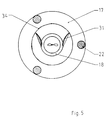
- turbulence screens 31 are rotatably mounted on a rotating circle 34 above the outflow openings in order to intercept the turbulence after the potential vortex has flowed out into the overflowing parallel flow.
- the turbulence screens 31 are adjusted by the wind and cause the potential vortex coils emerging from the outflow openings 10 to flow away in a controlled manner.
- the potential vortices emerging from the two flow modules according to FIG. 2 still exist outside the area of the flow modules 1 and form one through mutual induction Secondary vortex coil, which induces a secondary flow field, which partially increases the flow velocity of the parallel flow.
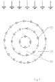
- FIG. 6 shows several arrangements according to FIG. 2 for forming a tower as a wind energy installation 32.
- the inflow columns 30 and the columns 22 form the supporting structure, which are statically stabilized by the base plate 11 and the plate 12. 7, such wind turbines 32 can be arranged on concentric circles of a base area, the annular areas between the wind turbines 32 forming calming zones 33.
- the distances between the wind energy plants 32 are chosen so that each wind energy plant 32 can form backpressures of the same size in the main wind direction.
Landscapes
- Engineering & Computer Science (AREA)
- Life Sciences & Earth Sciences (AREA)
- Sustainable Development (AREA)
- Sustainable Energy (AREA)
- Chemical & Material Sciences (AREA)
- Combustion & Propulsion (AREA)
- Mechanical Engineering (AREA)
- General Engineering & Computer Science (AREA)
- Wind Motors (AREA)
- Physical Or Chemical Processes And Apparatus (AREA)
- Radiation-Therapy Devices (AREA)
- Hydraulic Turbines (AREA)
- Crystals, And After-Treatments Of Crystals (AREA)
- Current-Collector Devices For Electrically Propelled Vehicles (AREA)
- Medicines Containing Material From Animals Or Micro-Organisms (AREA)
- Diaphragms For Electromechanical Transducers (AREA)
- Generation Of Surge Voltage And Current (AREA)
- Other Liquid Machine Or Engine Such As Wave Power Use (AREA)
Claims (11)
- Méthode de génération de l'énergie utile des courants parallèles qui, pour générer un tourbillon de potentiel, affluent un module de courant comprenant au moins un orifice d'admission et au moins un orifice d'évacuation, la méthode causant la génération du tourbillon de potentiel par l'intermédiaire d'un courant rotatoire spiralé, au moyen duquel une turbine arrangée en direction effective du tourbillon est actionnée comme convertisseur d'énergie,
caractérisé en ce que le courant rotatoire spiralé est généré par l'intermédiaire de la pression dynamique qui est produite par le courant parallèle affluant le module de courant, la pression dynamique agissant sur un corps creux extérieur formé d'une multiplicité des trappes mobiles ouvrant une part de ces trappes et, à l'intérieur du corps creux extérieur, une pression totale s'éleve qui ferme les trappes qui ne sont pas saisies par la pression dynamique; que le courant rotatoire, en train de s'engendrer, est, par un élément de séparation présentant un orifice de pénétration, divisé en un premier courant partiel et un deuxième courant partiel et le courant rotatoire du premier courant partiel est transformé, par l'intermédiaire d'un corps creux intérieur afflué de manière tangentiellement accélérée, en un courant de torsion qui, par la pression subatmosphérique régnant à l'orifice d'évacuation du corps creux intérieur, cet orifice étant, en même temps, l'orifice d'évacuation du module de courant, est dirigé vers l'extérieur, le tourbillon de potentiel étant formé du courant de torsion après son passage à travers l'orifice d'évacuation par les efforts de cisaillement du courant parallèle passant ledit orifice, ce tourbillon de potentiel tirant, du deuxième courant partiel et/ou du dehors, un courant de volume à travers l'orifice de pénétration d'élément de séparation vers l'intérieur du corps creux intérieur, et que, du deuxième courant partiel, une pluralité des courants tourbillonnaires sont générés au moyen d'une multiplicité des éléments produisant des tourbillons, lesdits courants tourbillonnaires étant également guidés jusqu'au coeur du corps creux intérieur et intensifiant le champ de courant du tourbillon de potentiel. - Méthode selon Revendication 1, caractérisé en ce que les éléments produisant des tourbillons sont tournés dans leur totalité.
- Dispositif pour générer de l'énergie utile des courants parallèles, comprenant un module de courant, qui a au moins un orifice d'admission et au moins un orifice d'évacuation et qui sert de générer un tourbillon de potentiel, ainsi qu'une turbine arrangée en direction effective du tourbillon de potentiel,
caractérisé en ce que le module (1) de courant présente un corps creux (3) extérieur, qui est constitué par une pluralité des trappes (4) et qui, des deux côtés, est couvert de plaques (11, 12), et l'orifice (10) d'évacuation est prévu dans une plaque (11), les trappes (4), sous l'influence de la pression dynamique du courant parallèle, s'ouvrant et/ou se fermant de manière automatique autour des axes de pivotement axiaux; que, concentriquement au corps creux (3) extérieur et à l'intérieur de ce corps, un corps creux (9) intérieur est arrangé, comprenant au moins un orifice (28) d'admission pour une admission tangentielle, et l'une extrémité de ce corps forme l'orifice (10) d'évacuation du module (1) de courant alors que l'autre extrémité dudit corps est couverte d'un élément (5) de séparation arrangé radialement dans le corps creux (3) extérieur, en laissant libre un orifice de pénétration, et que, dans la région (7) séparée du corps creux (9) intérieur par l'élément (5) de séparation, une multiplicité des éléments (16) produisant des tourbillons sont prévus, dont les courants tourbillonnaires sont dirigés vers l'intérieur du corps creux (9) intérieur. - Dispositif selon Revendication 3, caractérisé en ce que les éléments produisant des tourbillons sont construits en forme des ailes portantes et, dans la région d'orifice (8) de pénétration d'élément (5) de séparation, sont arrangés autour de cet orifice.
- Dispositif selon Revendication 3, caractérisé en ce que les éléments (16) produisant des tourbillons sont construits comme tuyères à turbulence arrangées en forme d'anneau, de préférence en forme de cône, les orifices d'évacuation dudites tuyères étant dirigés vers l'intérieur du corps creux (9) intérieur et les orifices d'admission dudites tuyères étant, dans la région (7) séparée du corps creux (9) intérieur, construits de sorte qu'ils entraînent une admission tangentielle.
- Dispositif selon quelconque des Revendications 3 à 5, caractérisé en ce que les éléments (16) produisant des tourbillons sont arrangés de sorte qu'ils peuvent être tournés comme une unité.
- Dispositif selon quelconque des Revendications 3 à 6, caractérisé en ce que l'orifice (10) d'évacuation du module (1) de courant est entouré d'un mécanisme (18) de guidage tronconique qui, de préférence, est pourvu des fentes ouvertes vers extérieur.
- Dispositif selon quelconque des Revendications 3 à 7, caractérisé en ce qu'un autre élément (37) de séparation est arrangé dans la région (7) séparée du corps creux (9) intérieur, les orifices (23) d'admission des éléments (16) produisant des tourbillons étant prévus seulement dans une partie de la région (7) séparée du corps creux (9) intérieur.
- Dispositif selon quelconque des Revendications 3 à 8, caractérisé en ce que le corps creux (3) extérieur est entouré des colonnes d'affluence qui présentent un profil en travers en forme d'un triangle isocèle au segment de cercle rapporté, les surfaces droites des colonnes (30) d'affluence constituant les surfaces (2) d'affluence qui sont dirigées vers l'extérieur.
- Dispositif selon quelconque des Revendications 3 à 9, caractérisé en ce qu'un écran-turbulence (31) rotatif pour effectuer une décharge commandée du tourbillon de potentiel est arrangé au-dessus d'orifice (10) d'évacuation.
- Dispositif selon quelconque des Revendications 3 à 10, caractérisé en ce qu'au moins deux modules (1) de courant sont arrangés l'un sur l'autre en étant séparés l'un de l'autre, les orifices (10) d'évacuation étant en face l'un de l'autre.
Applications Claiming Priority (3)
| Application Number | Priority Date | Filing Date | Title |
|---|---|---|---|
| DE4117838A DE4117838A1 (de) | 1991-05-29 | 1991-05-29 | Verfahren und einrichtung zur energetischen nutzung gasfoermiger stoffstroeme, insbesondere langsam fliessender stoffstroeme |
| DE4117838 | 1991-05-29 | ||
| PCT/DE1992/000450 WO1992021878A1 (fr) | 1991-05-29 | 1992-05-29 | Procede et installation destines a produire de l'energie exploitables a partir de d'ecoulements paralleles |
Publications (2)
| Publication Number | Publication Date |
|---|---|
| EP0591467A1 EP0591467A1 (fr) | 1994-04-13 |
| EP0591467B1 true EP0591467B1 (fr) | 1995-12-20 |
Family
ID=6432870
Family Applications (1)
| Application Number | Title | Priority Date | Filing Date |
|---|---|---|---|
| EP92917327A Expired - Lifetime EP0591467B1 (fr) | 1991-05-29 | 1992-05-29 | Procede et installation destines a produire de l'energie exploitables a partir de d'ecoulements paralleles |
Country Status (19)
| Country | Link |
|---|---|
| US (1) | US5478197A (fr) |
| EP (1) | EP0591467B1 (fr) |
| JP (1) | JPH06507693A (fr) |
| AT (1) | ATE131906T1 (fr) |
| AU (2) | AU666308B2 (fr) |
| BG (1) | BG61195B1 (fr) |
| BR (1) | BR9206076A (fr) |
| CA (1) | CA2110154A1 (fr) |
| CZ (1) | CZ279647B6 (fr) |
| DE (2) | DE4117838A1 (fr) |
| DK (1) | DK0591467T3 (fr) |
| ES (1) | ES2085640T3 (fr) |
| FI (1) | FI935276A7 (fr) |
| GR (1) | GR3019378T3 (fr) |
| HU (1) | HUT66089A (fr) |
| NO (1) | NO934287L (fr) |
| RU (1) | RU2089749C1 (fr) |
| SK (1) | SK278118B6 (fr) |
| WO (1) | WO1992021878A1 (fr) |
Cited By (1)
| Publication number | Priority date | Publication date | Assignee | Title |
|---|---|---|---|---|
| DE19548637A1 (de) * | 1995-12-13 | 1997-06-19 | Juergen Schatz | Verfahren und Einrichtung zur partiellen Konzentration und energetischen Nutzung von Strömungsenergie in Parallelströmungen |
Families Citing this family (33)
| Publication number | Priority date | Publication date | Assignee | Title |
|---|---|---|---|---|
| DE4429376A1 (de) * | 1994-08-12 | 1996-02-15 | Juergen Schatz | Verfahren und Einrichtung zur Leistungserhöhung von Vertikalachsenrotoren in Strömungsmodulen |
| DE19515319C2 (de) * | 1995-04-20 | 1997-04-24 | Juergen Schatz | Einrichtung zur Verstärkung und Gleichrichtung einer durch Unterdruck in einem Wirbel angetriebenen Axialströmung |
| PL324623A1 (en) * | 1995-07-06 | 1998-06-08 | Schatz Jurgen | Wind turbine having its axis perpendiculat to wind direction |
| DE19623313C2 (de) * | 1996-06-01 | 1998-04-23 | Juergen Schatz | Verfahren zur Energietransformation und energetischen Nutzung von Strömungen in Parallelströmungen |
| WO1998001671A1 (fr) | 1996-07-05 | 1998-01-15 | Schatz Juergen | Procede et dispositif d'exploitation energetique d'energie d'ecoulement |
| US6177735B1 (en) | 1996-10-30 | 2001-01-23 | Jamie C. Chapman | Integrated rotor-generator |
| DE29710524U1 (de) * | 1997-06-17 | 1998-10-15 | Kunz, Ulrich, 38678 Clausthal-Zellerfeld | Windkraftanlage |
| DE19748953A1 (de) * | 1997-10-29 | 1999-05-06 | Juergen Schatz | Verfahren und Einrichtung zur Erzeugung von Drehmomenten zur energetischen Nutzung von Strömungsenergie |
| WO2000042319A1 (fr) * | 1999-01-11 | 2000-07-20 | Pike Andrew Thomas | Turbine a vent cyclonique |
| US5982046A (en) * | 1999-04-29 | 1999-11-09 | Minh; Vu Xuan | Wind power plant with an integrated acceleration system |
| US6518680B2 (en) | 2000-11-17 | 2003-02-11 | Mcdavid, Jr. William K. | Fluid-powered energy conversion device |
| DE10102672C2 (de) | 2001-01-17 | 2003-02-27 | Juergen G Schatz | Verfahren und Vorrichtung zur Fluidkraftnutzung |
| DE10129620A1 (de) * | 2001-06-16 | 2003-01-09 | Juergen G Schatz | Hurricanenergie Transformer |
| WO2002102838A2 (fr) * | 2001-06-16 | 2002-12-27 | Schatz Juergen | Procede et dispositifs destines a la transformation et la concentration d'energie et utilisation de forces d'inertie dans des systemes rotatifs |
| EA003784B1 (ru) * | 2001-11-08 | 2003-08-28 | Альберт Васильевич Болотов | Ветроэнергетический агрегат (вэа) и ветроэлектростанция (вэс) |
| US6943461B2 (en) | 2002-04-29 | 2005-09-13 | Solomon Kaploun | All-weather energy and water production via steam-enhanced vortex tower |
| US7154190B2 (en) * | 2002-04-29 | 2006-12-26 | Solomon Kaploun | All-weather energy and water production via steam-enhanced vortex tower |
| US7511387B2 (en) * | 2003-10-04 | 2009-03-31 | Mehdi Fakhrai | Method and apparatus for producing energy using air pressure differential |
| US6984899B1 (en) * | 2004-03-01 | 2006-01-10 | The United States Of America As Represented By The Secretary Of The Navy | Wind dam electric generator and method |
| US20070035138A1 (en) * | 2005-07-18 | 2007-02-15 | Khan Sajid A | Vacuum powered generators |
| US7211905B1 (en) | 2005-11-15 | 2007-05-01 | Mcdavid Jr William K | Vehicle-mounted generator |
| RU2352810C2 (ru) * | 2007-03-29 | 2009-04-20 | Сергей Альбертович Болотов | Ветроэнергетический агрегат |
| RU2373429C2 (ru) * | 2007-05-25 | 2009-11-20 | Автономная некоммерческая научная организация "Международный институт ноосферных технологий" (АННО МИНТ) | Солнечная теплоэлектростанция с ветронаправляющими поверхностями |
| RU2373430C2 (ru) * | 2007-05-25 | 2009-11-20 | Автономная некоммерческая научная организация "Международный институт ноосферных технологий" (АННО МИНТ) | Солнечная теплоэлектростанция с применением вихревых камер |
| RU2341682C1 (ru) * | 2007-06-13 | 2008-12-20 | Российская академия сельскохозяйственных наук Государственное научное учреждение Всероссийский научно-исследовательский институт электрификации сельского хозяйства (ГНУ ВИЭСХ РООССЕЛЬХОЗАКАДЕМИИ) | Ветроустановка (варианты) |
| WO2009076704A1 (fr) * | 2007-12-19 | 2009-06-25 | Etergen Limited | Appareil de génération d'énergie électrique exploitant l'énergie des vagues et du vent |
| CN101603511B (zh) * | 2009-07-16 | 2011-07-27 | 广州雅图风电设备制造有限公司 | 一种垂直风力发电机 |
| WO2011032249A1 (fr) * | 2009-09-16 | 2011-03-24 | Horia Nica | Noyau de rotor creux destiné à produire un vortex dans une éolienne |
| US8358030B2 (en) | 2011-03-17 | 2013-01-22 | Via Verde Limited | Wind turbine apparatus |
| US20160186725A1 (en) * | 2016-03-04 | 2016-06-30 | Nestor Dofredo | Thermal wind turbines |
| US20200049123A1 (en) * | 2018-04-27 | 2020-02-13 | Peter C. Whittington | Vortex hydroturbine and method for operating the vortex hydroturbine |
| RU2714026C1 (ru) * | 2018-10-17 | 2020-02-11 | Андрей Вячеславович Прищепов | Многоцелевая энергетическая система (МЭС) |
| WO2024172690A1 (fr) * | 2023-02-14 | 2024-08-22 | Григорий Аврамович РАДУЦКИЙ | Générateur éolien de type turbine |
Family Cites Families (10)
| Publication number | Priority date | Publication date | Assignee | Title |
|---|---|---|---|---|
| DE823430C (de) * | 1949-07-30 | 1951-12-03 | Carl Fleck | Windkraft-Kesselturbine |
| BE511378A (fr) * | 1951-06-23 | 1900-01-01 | ||
| US4309146A (en) * | 1980-03-12 | 1982-01-05 | The United States Of America As Represented By The Administrator Of The National Aeronautics And Space Administration | Amplified wind turbine apparatus |
| ES8301330A1 (es) * | 1980-07-24 | 1982-12-01 | Central Energetic Ciclonic | Sistema para la obtencion de energia mediante flujos simili-lares a los que conforman un ciclon o un anticiclon natural |
| IT1194134B (it) * | 1981-01-26 | 1988-09-14 | Rex Rotary International | Meccanismo per la separazione di fogli per macchine da stampa e copiatrici,in particolare per macchine duplicatrici |
| ES505720A0 (es) * | 1981-09-23 | 1982-06-16 | Zaratain Fernandez Guillermo D | Perfeccionamientos en instalaciones para transformar la energia eolica en energia electrica |
| US4452562A (en) * | 1983-05-06 | 1984-06-05 | Iowa State University Research Foundation, Inc. | Tornado type wind turbines |
| DE3330899A1 (de) * | 1983-08-25 | 1985-03-14 | Ingo Prof. Dr.-Ing. 1000 Berlin Rechenberg | Anordnung zur vergroesserung der geschwindigkeit eines gas- oder fluessigkeitsstromes |
| FR2588317A1 (fr) * | 1985-10-08 | 1987-04-10 | Viaud Gabriel | Aerogenerateur orientable a vortex |
| DE4107208A1 (de) * | 1991-03-04 | 1992-09-10 | Juergen Schatz | Verfahren und einrichtung zur energieerzeugung aus gasfoermigen stoffstroemen |
-
1991
- 1991-05-29 DE DE4117838A patent/DE4117838A1/de not_active Ceased
-
1992
- 1992-05-29 ES ES92917327T patent/ES2085640T3/es not_active Expired - Lifetime
- 1992-05-29 AT AT92917327T patent/ATE131906T1/de not_active IP Right Cessation
- 1992-05-29 HU HU9303363A patent/HUT66089A/hu unknown
- 1992-05-29 AU AU18710/92A patent/AU666308B2/en not_active Ceased
- 1992-05-29 EP EP92917327A patent/EP0591467B1/fr not_active Expired - Lifetime
- 1992-05-29 CA CA002110154A patent/CA2110154A1/fr not_active Abandoned
- 1992-05-29 RU RU9293058300A patent/RU2089749C1/ru active
- 1992-05-29 WO PCT/DE1992/000450 patent/WO1992021878A1/fr not_active Ceased
- 1992-05-29 JP JP4510097A patent/JPH06507693A/ja active Pending
- 1992-05-29 DE DE59204776T patent/DE59204776D1/de not_active Expired - Fee Related
- 1992-05-29 US US08/142,391 patent/US5478197A/en not_active Expired - Fee Related
- 1992-05-29 SK SK1339-93A patent/SK278118B6/sk unknown
- 1992-05-29 BR BR9206076A patent/BR9206076A/pt not_active Application Discontinuation
- 1992-05-29 CZ CS932571A patent/CZ279647B6/cs unknown
- 1992-05-29 DK DK92917327.6T patent/DK0591467T3/da active
-
1993
- 1993-11-26 FI FI935276A patent/FI935276A7/fi unknown
- 1993-11-26 NO NO934287A patent/NO934287L/no unknown
- 1993-11-29 BG BG98250A patent/BG61195B1/bg unknown
-
1996
- 1996-03-20 GR GR960400778T patent/GR3019378T3/el unknown
- 1996-05-08 AU AU52131/96A patent/AU687677B2/en not_active Ceased
Cited By (1)
| Publication number | Priority date | Publication date | Assignee | Title |
|---|---|---|---|---|
| DE19548637A1 (de) * | 1995-12-13 | 1997-06-19 | Juergen Schatz | Verfahren und Einrichtung zur partiellen Konzentration und energetischen Nutzung von Strömungsenergie in Parallelströmungen |
Also Published As
| Publication number | Publication date |
|---|---|
| ATE131906T1 (de) | 1996-01-15 |
| GR3019378T3 (en) | 1996-06-30 |
| BG61195B1 (bg) | 1997-02-28 |
| ES2085640T3 (es) | 1996-06-01 |
| RU2089749C1 (ru) | 1997-09-10 |
| NO934287L (no) | 1994-01-26 |
| DK0591467T3 (da) | 1996-07-08 |
| AU687677B2 (en) | 1998-02-26 |
| BR9206076A (pt) | 1994-11-15 |
| DE59204776D1 (de) | 1996-02-01 |
| WO1992021878A1 (fr) | 1992-12-10 |
| EP0591467A1 (fr) | 1994-04-13 |
| NO934287D0 (no) | 1993-11-26 |
| SK133993A3 (en) | 1994-07-06 |
| AU666308B2 (en) | 1996-02-08 |
| FI935276A7 (fi) | 1994-01-17 |
| CZ279647B6 (cs) | 1995-05-17 |
| HUT66089A (en) | 1994-09-28 |
| JPH06507693A (ja) | 1994-09-01 |
| AU1871092A (en) | 1993-01-08 |
| AU5213196A (en) | 1996-07-11 |
| CA2110154A1 (fr) | 1992-12-10 |
| SK278118B6 (en) | 1996-02-07 |
| FI935276A0 (fi) | 1993-11-26 |
| US5478197A (en) | 1995-12-26 |
| BG98250A (bg) | 1994-08-30 |
| CZ257193A3 (en) | 1994-05-18 |
| DE4117838A1 (de) | 1992-12-03 |
Similar Documents
| Publication | Publication Date | Title |
|---|---|---|
| EP0591467B1 (fr) | Procede et installation destines a produire de l'energie exploitables a partir de d'ecoulements paralleles | |
| DE19920560A1 (de) | Windkraftanlage mit Vertikalrotor | |
| WO2003060319A1 (fr) | Element intermediaire monte a la base d'une pale d'eolienne destine a augmenter l'ecart entre l'extremite de la pale et la tour | |
| DE19957141A1 (de) | Windkraftanlage mit Vertikalrotor und Frontalanströmung | |
| CH699133B1 (de) | Wasserwirbelkraftwerk. | |
| DE3315439A1 (de) | Einrichtung zur umformung der natuerlichen stroemungsenergie von wasser bzw. luft | |
| DE3303898C2 (de) | Verfahren zur Windenergienutzung, sowie dazugehörige Vorrichtung | |
| DE4309588A1 (de) | Verfahren und Einrichtung zur Erzeugung energetisch nutzbarer Vorticity aus Parallelströmungen | |
| CH714302B1 (de) | Aerodynamisch optimiertes Rotorblatt. | |
| DE19548637C2 (de) | Vorrichtung zur partiellen Konzentration und energetischen Nutzung von Strömungsenergie in Parallelströmungen | |
| EP2699797B1 (fr) | Installation éolienne | |
| DE19525910C2 (de) | Verfahren und Einrichtung zur Erzeugung und energetischen Nutzung von Wirbelströmungen hoher Zirkulation in parallelen Hauptströmungen | |
| DE29907940U1 (de) | Windkraftanlage mit Vertikalrotor | |
| DE10145865A1 (de) | Wind- und Wasserkraftanlage mit vertikalen Durchströmrotoren | |
| EP1472457A1 (fr) | Turbine eolienne a chemise | |
| DE102009022537A1 (de) | Windenergieanlage mit offener Gondelbauweise | |
| DE2153192C3 (de) | Überschallradialverdichter | |
| DE20108925U1 (de) | Strömungsenergieanlage, insbesondere Windkraftanlage | |
| DE102013010837B4 (de) | Verfahren und Vorrichtungen zur Herstellung und wirtschaftlichen Nutzung erneuerbarer Energieträger in newtonschen Fluiden | |
| WO1998001671A1 (fr) | Procede et dispositif d'exploitation energetique d'energie d'ecoulement | |
| DE10028053A1 (de) | Strömungskraftmaschine zur Nutzung geringer Druckdifferenzen | |
| DE102009014097A1 (de) | Verfahren zur effizienten Nutzung eines Wirbelrohres bei der Umwandlung von Strömungsenergie in andere Energieformen und Einrichtung hierfür | |
| DE102010035178B4 (de) | Windkraftanlage | |
| DE19539393A1 (de) | Verfahren und Einrichtung zur Erzeugung und energetischen Nutzung von Wirbelströmungen hoher Geschwindigkeits- und/oder Massenkonzentrationen sowie Zirkulation | |
| DE19549476A1 (de) | Verfahren zur partiellen Konzentration und energetischen Nutzung von Strömungsenergie in Parallelströmungen |
Legal Events
| Date | Code | Title | Description |
|---|---|---|---|
| PUAI | Public reference made under article 153(3) epc to a published international application that has entered the european phase |
Free format text: ORIGINAL CODE: 0009012 |
|
| 17P | Request for examination filed |
Effective date: 19931227 |
|
| AK | Designated contracting states |
Kind code of ref document: A1 Designated state(s): AT BE CH DE DK ES FR GB GR IT LI LU NL SE |
|
| 17Q | First examination report despatched |
Effective date: 19950508 |
|
| GRAA | (expected) grant |
Free format text: ORIGINAL CODE: 0009210 |
|
| AK | Designated contracting states |
Kind code of ref document: B1 Designated state(s): AT BE CH DE DK ES FR GB GR IT LI LU NL SE |
|
| REF | Corresponds to: |
Ref document number: 131906 Country of ref document: AT Date of ref document: 19960115 Kind code of ref document: T |
|
| RAP4 | Party data changed (patent owner data changed or rights of a patent transferred) |
Owner name: SCHATZ, OLAF Owner name: SCHATZ, JUERGEN |
|
| REF | Corresponds to: |
Ref document number: 59204776 Country of ref document: DE Date of ref document: 19960201 |
|
| REG | Reference to a national code |
Ref country code: CH Ref legal event code: NV Representative=s name: SCHAAD, BALASS & PARTNER AG |
|
| ITF | It: translation for a ep patent filed | ||
| GBT | Gb: translation of ep patent filed (gb section 77(6)(a)/1977) |
Effective date: 19960321 |
|
| ET | Fr: translation filed | ||
| REG | Reference to a national code |
Ref country code: GR Ref legal event code: FG4A Free format text: 3019378 |
|
| REG | Reference to a national code |
Ref country code: ES Ref legal event code: FG2A Ref document number: 2085640 Country of ref document: ES Kind code of ref document: T3 |
|
| REG | Reference to a national code |
Ref country code: DK Ref legal event code: T3 |
|
| PLBE | No opposition filed within time limit |
Free format text: ORIGINAL CODE: 0009261 |
|
| 26N | No opposition filed | ||
| PGFP | Annual fee paid to national office [announced via postgrant information from national office to epo] |
Ref country code: GR Payment date: 19980529 Year of fee payment: 7 Ref country code: GB Payment date: 19980529 Year of fee payment: 7 Ref country code: FR Payment date: 19980529 Year of fee payment: 7 Ref country code: ES Payment date: 19980529 Year of fee payment: 7 |
|
| PGFP | Annual fee paid to national office [announced via postgrant information from national office to epo] |
Ref country code: NL Payment date: 19980531 Year of fee payment: 7 Ref country code: AT Payment date: 19980531 Year of fee payment: 7 |
|
| PGFP | Annual fee paid to national office [announced via postgrant information from national office to epo] |
Ref country code: SE Payment date: 19980602 Year of fee payment: 7 Ref country code: DK Payment date: 19980602 Year of fee payment: 7 |
|
| PGFP | Annual fee paid to national office [announced via postgrant information from national office to epo] |
Ref country code: BE Payment date: 19980612 Year of fee payment: 7 |
|
| PGFP | Annual fee paid to national office [announced via postgrant information from national office to epo] |
Ref country code: LU Payment date: 19980615 Year of fee payment: 7 |
|
| PGFP | Annual fee paid to national office [announced via postgrant information from national office to epo] |
Ref country code: CH Payment date: 19980629 Year of fee payment: 7 |
|
| PGFP | Annual fee paid to national office [announced via postgrant information from national office to epo] |
Ref country code: DE Payment date: 19980708 Year of fee payment: 7 |
|
| PG25 | Lapsed in a contracting state [announced via postgrant information from national office to epo] |
Ref country code: LU Free format text: LAPSE BECAUSE OF NON-PAYMENT OF DUE FEES Effective date: 19990529 Ref country code: GB Free format text: LAPSE BECAUSE OF NON-PAYMENT OF DUE FEES Effective date: 19990529 Ref country code: AT Free format text: LAPSE BECAUSE OF NON-PAYMENT OF DUE FEES Effective date: 19990529 |
|
| PG25 | Lapsed in a contracting state [announced via postgrant information from national office to epo] |
Ref country code: SE Free format text: LAPSE BECAUSE OF NON-PAYMENT OF DUE FEES Effective date: 19990530 |
|
| PG25 | Lapsed in a contracting state [announced via postgrant information from national office to epo] |
Ref country code: LI Free format text: LAPSE BECAUSE OF NON-PAYMENT OF DUE FEES Effective date: 19990531 Ref country code: GR Free format text: LAPSE BECAUSE OF NON-PAYMENT OF DUE FEES Effective date: 19990531 Ref country code: ES Free format text: THE PATENT HAS BEEN ANNULLED BY A DECISION OF A NATIONAL AUTHORITY Effective date: 19990531 Ref country code: DK Free format text: LAPSE BECAUSE OF NON-PAYMENT OF DUE FEES Effective date: 19990531 Ref country code: CH Free format text: LAPSE BECAUSE OF NON-PAYMENT OF DUE FEES Effective date: 19990531 Ref country code: BE Free format text: LAPSE BECAUSE OF NON-PAYMENT OF DUE FEES Effective date: 19990531 |
|
| BERE | Be: lapsed |
Owner name: SCHATZ OLAF Effective date: 19990531 Owner name: SCHATZ JURGEN Effective date: 19990531 |
|
| PG25 | Lapsed in a contracting state [announced via postgrant information from national office to epo] |
Ref country code: NL Free format text: LAPSE BECAUSE OF NON-PAYMENT OF DUE FEES Effective date: 19991201 |
|
| REG | Reference to a national code |
Ref country code: CH Ref legal event code: PL |
|
| GBPC | Gb: european patent ceased through non-payment of renewal fee |
Effective date: 19990529 |
|
| EUG | Se: european patent has lapsed |
Ref document number: 92917327.6 |
|
| PG25 | Lapsed in a contracting state [announced via postgrant information from national office to epo] |
Ref country code: FR Free format text: LAPSE BECAUSE OF NON-PAYMENT OF DUE FEES Effective date: 20000131 |
|
| NLV4 | Nl: lapsed or anulled due to non-payment of the annual fee |
Effective date: 19991201 |
|
| PG25 | Lapsed in a contracting state [announced via postgrant information from national office to epo] |
Ref country code: DE Free format text: LAPSE BECAUSE OF NON-PAYMENT OF DUE FEES Effective date: 20000301 |
|
| REG | Reference to a national code |
Ref country code: FR Ref legal event code: ST |
|
| REG | Reference to a national code |
Ref country code: DK Ref legal event code: EBP |
|
| REG | Reference to a national code |
Ref country code: ES Ref legal event code: FD2A Effective date: 20010604 |
|
| PG25 | Lapsed in a contracting state [announced via postgrant information from national office to epo] |
Ref country code: IT Free format text: LAPSE BECAUSE OF NON-PAYMENT OF DUE FEES;WARNING: LAPSES OF ITALIAN PATENTS WITH EFFECTIVE DATE BEFORE 2007 MAY HAVE OCCURRED AT ANY TIME BEFORE 2007. THE CORRECT EFFECTIVE DATE MAY BE DIFFERENT FROM THE ONE RECORDED. Effective date: 20050529 |