EP0591482B1 - Dispositif pour le transfert de commandes dans un appareil ou une machine fonctionnant sur le reseau - Google Patents
Dispositif pour le transfert de commandes dans un appareil ou une machine fonctionnant sur le reseau Download PDFInfo
- Publication number
- EP0591482B1 EP0591482B1 EP93905723A EP93905723A EP0591482B1 EP 0591482 B1 EP0591482 B1 EP 0591482B1 EP 93905723 A EP93905723 A EP 93905723A EP 93905723 A EP93905723 A EP 93905723A EP 0591482 B1 EP0591482 B1 EP 0591482B1
- Authority
- EP
- European Patent Office
- Prior art keywords
- working means
- control command
- control
- arrangement according
- wire
- Prior art date
- Legal status (The legal status is an assumption and is not a legal conclusion. Google has not performed a legal analysis and makes no representation as to the accuracy of the status listed.)
- Expired - Lifetime
Links
Images

Classifications
-
- H—ELECTRICITY
- H02—GENERATION; CONVERSION OR DISTRIBUTION OF ELECTRIC POWER
- H02J—ELECTRIC POWER NETWORKS; CIRCUIT ARRANGEMENTS OR SYSTEMS FOR SUPPLYING OR DISTRIBUTING ELECTRIC POWER; SYSTEMS FOR STORING ELECTRIC ENERGY
- H02J13/00—Circuit arrangements for providing remote monitoring or remote control of equipment in a power distribution network
- H02J13/13—Circuit arrangements for providing remote monitoring or remote control of equipment in a power distribution network characterised by the transmission of data to equipment in the power network
- H02J13/1311—Circuit arrangements for providing remote monitoring or remote control of equipment in a power distribution network characterised by the transmission of data to equipment in the power network using the power network as support for the transmission
- H02J13/1315—Circuit arrangements for providing remote monitoring or remote control of equipment in a power distribution network characterised by the transmission of data to equipment in the power network using the power network as support for the transmission using modification of a parameter of the network power signal
-
- H—ELECTRICITY
- H02—GENERATION; CONVERSION OR DISTRIBUTION OF ELECTRIC POWER
- H02J—ELECTRIC POWER NETWORKS; CIRCUIT ARRANGEMENTS OR SYSTEMS FOR SUPPLYING OR DISTRIBUTING ELECTRIC POWER; SYSTEMS FOR STORING ELECTRIC ENERGY
- H02J13/00—Circuit arrangements for providing remote monitoring or remote control of equipment in a power distribution network
- H02J13/13—Circuit arrangements for providing remote monitoring or remote control of equipment in a power distribution network characterised by the transmission of data to equipment in the power network
- H02J13/1311—Circuit arrangements for providing remote monitoring or remote control of equipment in a power distribution network characterised by the transmission of data to equipment in the power network using the power network as support for the transmission
- H02J13/1313—Circuit arrangements for providing remote monitoring or remote control of equipment in a power distribution network characterised by the transmission of data to equipment in the power network using the power network as support for the transmission using pulsed signals
-
- Y—GENERAL TAGGING OF NEW TECHNOLOGICAL DEVELOPMENTS; GENERAL TAGGING OF CROSS-SECTIONAL TECHNOLOGIES SPANNING OVER SEVERAL SECTIONS OF THE IPC; TECHNICAL SUBJECTS COVERED BY FORMER USPC CROSS-REFERENCE ART COLLECTIONS [XRACs] AND DIGESTS
- Y02—TECHNOLOGIES OR APPLICATIONS FOR MITIGATION OR ADAPTATION AGAINST CLIMATE CHANGE
- Y02B—CLIMATE CHANGE MITIGATION TECHNOLOGIES RELATED TO BUILDINGS, e.g. HOUSING, HOUSE APPLIANCES OR RELATED END-USER APPLICATIONS
- Y02B90/00—Enabling technologies or technologies with a potential or indirect contribution to GHG emissions mitigation
- Y02B90/20—Smart grids as enabling technology in buildings sector
-
- Y—GENERAL TAGGING OF NEW TECHNOLOGICAL DEVELOPMENTS; GENERAL TAGGING OF CROSS-SECTIONAL TECHNOLOGIES SPANNING OVER SEVERAL SECTIONS OF THE IPC; TECHNICAL SUBJECTS COVERED BY FORMER USPC CROSS-REFERENCE ART COLLECTIONS [XRACs] AND DIGESTS
- Y02—TECHNOLOGIES OR APPLICATIONS FOR MITIGATION OR ADAPTATION AGAINST CLIMATE CHANGE
- Y02E—REDUCTION OF GREENHOUSE GAS [GHG] EMISSIONS, RELATED TO ENERGY GENERATION, TRANSMISSION OR DISTRIBUTION
- Y02E60/00—Enabling technologies; Technologies with a potential or indirect contribution to GHG emissions mitigation
-
- Y—GENERAL TAGGING OF NEW TECHNOLOGICAL DEVELOPMENTS; GENERAL TAGGING OF CROSS-SECTIONAL TECHNOLOGIES SPANNING OVER SEVERAL SECTIONS OF THE IPC; TECHNICAL SUBJECTS COVERED BY FORMER USPC CROSS-REFERENCE ART COLLECTIONS [XRACs] AND DIGESTS
- Y04—INFORMATION OR COMMUNICATION TECHNOLOGIES HAVING AN IMPACT ON OTHER TECHNOLOGY AREAS
- Y04S—SYSTEMS INTEGRATING TECHNOLOGIES RELATED TO POWER NETWORK OPERATION, COMMUNICATION OR INFORMATION TECHNOLOGIES FOR IMPROVING THE ELECTRICAL POWER GENERATION, TRANSMISSION, DISTRIBUTION, MANAGEMENT OR USAGE, i.e. SMART GRIDS
- Y04S10/00—Systems supporting electrical power generation, transmission or distribution
- Y04S10/50—Systems or methods supporting the power network operation or management, involving a certain degree of interaction with the load-side end user applications
- Y04S10/52—Outage or fault management, e.g. fault detection or location
-
- Y—GENERAL TAGGING OF NEW TECHNOLOGICAL DEVELOPMENTS; GENERAL TAGGING OF CROSS-SECTIONAL TECHNOLOGIES SPANNING OVER SEVERAL SECTIONS OF THE IPC; TECHNICAL SUBJECTS COVERED BY FORMER USPC CROSS-REFERENCE ART COLLECTIONS [XRACs] AND DIGESTS
- Y04—INFORMATION OR COMMUNICATION TECHNOLOGIES HAVING AN IMPACT ON OTHER TECHNOLOGY AREAS
- Y04S—SYSTEMS INTEGRATING TECHNOLOGIES RELATED TO POWER NETWORK OPERATION, COMMUNICATION OR INFORMATION TECHNOLOGIES FOR IMPROVING THE ELECTRICAL POWER GENERATION, TRANSMISSION, DISTRIBUTION, MANAGEMENT OR USAGE, i.e. SMART GRIDS
- Y04S40/00—Systems for electrical power generation, transmission, distribution or end-user application management characterised by the use of communication or information technologies, or communication or information technology specific aspects supporting them
- Y04S40/12—Systems for electrical power generation, transmission, distribution or end-user application management characterised by the use of communication or information technologies, or communication or information technology specific aspects supporting them characterised by data transport means between the monitoring, controlling or managing units and monitored, controlled or operated electrical equipment
- Y04S40/121—Systems for electrical power generation, transmission, distribution or end-user application management characterised by the use of communication or information technologies, or communication or information technology specific aspects supporting them characterised by data transport means between the monitoring, controlling or managing units and monitored, controlled or operated electrical equipment using the power network as support for the transmission
Definitions
- the present invention pertains to an arrangement in an apparatus or a machine operated from the mains for the transfer of control commands to at least one working means in said apparatus or machine, e.g. a motor or the like, via a wire also used for the power supply to said working means, the arrangement comprising a control unit provided for creating a control command by suppressing, in a predetermined order, at least part of one or several consecutive half-periods of a predetermined polarity of the supply voltage, and a slave unit operating in response to the control command transmitted to activate the working means.
- the object of the invention is to remedy the drawback indicated and to provide an arrangement of a design such that the control commands transmitted can be unambiguously interpreted by the slave unit for the correct control of the working means to be operated.
- the object is achieved by an arrangement of the kind referred to above which is characterized by such a design of the control unit that before a control command is transmitted the control unit operates to shortly disconnect the supply voltage on the wire for a period of time required for the current in the working means to decline essentially to zero.
- the invention characterized above is the subject matter of the appending claim 1. Preferred embodiments have been included in the sub-claims.
- such a machine may comprise a dishwashing compartment supplied with water via a solenoid valve and drained of cleaning and rinsing liquid via a drainage pump. Further, in such machine a circulation pump is provided for the supply of cleaning and rinsing liquid to rotating spray-arms provided with holes and spraying liquid, in a conventional way, onto dish goods supported in baskets in the dish-washing compartment.
- a dosing device which via a door, which can be opened by magnetic means, supplies a dose of powder from a dosage compartment covered by said door.
- the various working means which in this case have to be controlled by a programmer are the circulation pump, the drain pump, the dosage device and the solenoid valve.
- the programmer is of the electronic type comprising a microprocessor, a program memory and additional electronic components required.
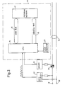
- the control arrangement comprises a control unit 10 and a slave unit 11 interconnected by a line 13, referred to as a bus line.
- a triac switch 20 is connected by which the voltage to the slave unit 11 can be broken, either permanently or temporary when a control command is to be transmitted.
- a working means 24 is connected to the slave unit 11 via a triac switch 27.
- the control unit consists of a microprocessor 14 which in a known way communicates, via an address bus 15 and a data bus 16, with a program memory 17.
- the bus line is connected to a mains AC network and via the triac switch 20 the bus line is connected to the slave unit 11.
- Said triac switch is controlled, via a driver circuit 21, from the microprocessor 14.
- An opto coupler 22 is used to supply phase information from the supplied AC voltage to the microprocessor.
- the microprocessor is also connected to a clock pulse generator 23.
- the microprocessor 14 and the program memory 17 constitute an electronic programmer determining the function of the connected machine, here the dishwasher, said programmer also controlling the activation of the different working means, here represented by the load 24, see Fig. 3.
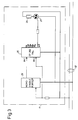
- the last-mentioned figure shows the slave unit 11 which comprises an electronic circuit 25 referred to as EP310 PAL Altera.
- the circuit has two inputs IN1 and IN2 of which IN1 is connected to a monostable flip-flop 26.
- the flip-flop is triggered by each positive half-period of the supply voltage generating pulses of a constant width.
- the second input IN2 of the circuit 25 is directly connected to the supply AC voltage and in a manner not disclosed in detail the circuit uses the positive half- periods on the input IN2 to be compared with the pulses on the input IN1 in order to determine the nature of the data information transferred, "1" or "0".
- the circuit 25 has a number of outputs Q0-Q4 to which the different loads are connected. In the example the only load 24 is connected to the output Q0 via a triac switch 27.
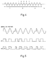
- control command comprises four additional bits and with respect to the output Q0 said command consists of three "0" followed by a "1".
- the real control command is shown in phase 2 of the diagram.
- the supply voltage is completely unaffected representing the condition in which the working means is activated.
- the working means is to be disconncted, the supply of current is disrupted by opening of the triac switch 20.
- This phase has been designated by 4 in the diagram.
- Fig. 5 those pulses are shown which have been discussed above and are present in the circuit 25 as the result of the signals on inputs IN1 and IN2.
- the circuit 25 is provided with a shift register, not shown, which is being filled with the ones and zeros which represent the transmitted control command.
- the control command is retrieved and gated to the corresponding output, in this case Q0, via a logic network or the like, activating said output and the working means connected thereto.
- the connection takes place by closing of a triac switch 27.
- the working means remains connected for a period determined by the electronic programmer and when said period has lapsed disconnection takes place by the triac switch 20 being operated to take its open position.
- both the control unit and the slave unit can be otherwise designed and with other components.
- the latter has been shown as provided with a number of outputs corresponding to the number of working means to be connected.
- a number of slave units can be provided where each slave unit is associated with one working means only.
- the code chosen can of course be modified in the desired way in accordance with known code patterns and the control unit can be modified accordingly.
- the invention has been made to be used primarily in dish-washing and laundry washing machines it can of course be applied in all those apparatuses and machines where there is a need for control commands to be sent for the connection and disconnection of working means having inductive properties.
Landscapes
- Power Engineering (AREA)
- Engineering & Computer Science (AREA)
- Control Of Ac Motors In General (AREA)
- Electrical Discharge Machining, Electrochemical Machining, And Combined Machining (AREA)
- Control Of Electric Motors In General (AREA)
- Selective Calling Equipment (AREA)
- Earth Drilling (AREA)
- Auxiliary Devices For And Details Of Packaging Control (AREA)
- Vending Machines For Individual Products (AREA)
- Remote Monitoring And Control Of Power-Distribution Networks (AREA)
- Suspension Of Electric Lines Or Cables (AREA)
- Yarns And Mechanical Finishing Of Yarns Or Ropes (AREA)
- Automatic Disk Changers (AREA)
- Toys (AREA)
Claims (8)
- Dispositif intégré dans un appareil ou une machine fonctionnant sur le secteur, pour la transmission d'instructions de commande à au moins un moyen actif (24) situé dans l'appareil ou la machine, par exemple un moteur ou un élément similaire, par l'intermédiaire d'un conducteur (13) également utilisé pour l'alimentation en puissance dudit moyen actif, le dispositif comprenant une unité de commande (10) prévue pour engendrer une instruction de commande en supprimant, dans un ordre prédéterminé, au moins une partie d'une ou plusieurs demi-périodes successives de la tension d'alimentation ; et une unité asservie (11) fonctionnant en réponse à l'instruction de commande transmise pour activer le moyen actif (24), caractérisé par le fait que l'unité de commande (10) est conçue de manière telle que, préalablement à la transmission d'une instruction de commande, l'unité de commande ait pour effet de déconnecter brièvement la tension d'alimentation, sur le conducteur (13), pendant un laps de temps nécessaire pour que le courant, circulant dans le moyen actif (24), décroisse pour l'essentiel jusqu'à zéro.
- Dispositif selon la revendication 1, caractérisé par le fait que les demi-périodes successives de la tension d'alimentation en courant alternatif présentent une polarité prédéterminée.
- Dispositif selon la revendication 1 ou 2, caractérisé par le fait que l'une des extrémités du conducteur (13) est connectée à un réseau de courant alternatif du secteur ; et par le fait qu'un commutateur électronique (20), prévu entre ladite extrémité et l'unité asservie (11), déconnecte la tension appliquée à l'unité asservie (11) en réponse à un signal de commande émanant de l'unité de commande (10), à la fois préalablement à la transmission d'une instruction de commande, et pour provoquer la suppression de demi-périodes prédéterminées formant l'instruction de commande.
- Dispositif selon l'une quelconque des revendications précédentes, caractérisé par le fait que le commutateur électronique (20) est un commutateur à triac.
- Dispositif selon l'une quelconque des revendications précédentes, caractérisé par le fait que, pour l'essentiel, 50 % de la demi-période positive de la tension d'alimentation en courant alternatif sont supprimés, de manière à instaurer l'un des deux états binaires d'un code binaire formant l'instruction de commande.
- Dispositif selon la revendication 5, caractérisé par le fait que l'unité asservie (11) comprend un circuit électronique (25) présentant deux entrées (IN1, IN2) et un certain nombre de sorties (Q0-Q4) correspondant au nombre de moyens actifs (24), l'une (IN1) desdites entrées étant connectée à une bascule monostable (26) pour recevoir, en provenance de ladite bascule, une impulsion positive de largeur constante engendrée à chaque fois qu'une demi-période positive apparaît sur le conducteur (13), tandis que l'autre entrée (IN2) est directement raccordée au conducteur, le circuit électronique (25) étant conçu de telle sorte qu'une comparaison entre les impulsions émanant de la bascule (26) et des impulsions engendrées par le circuit, en correspondance avec les demi-périodes positives sur la seconde entrée (IN2), décode l'instruction de commande transmise.
- Dispositif selon la revendication 6, caractérisé par le fait que le circuit électronique (25) comprend un registre à décalage dans lequel l'instruction transmise est introduite, dispositif dans lequel, lorsqu'un bit initial de ladite instruction a pris une position prédéterminée dans le registre à décalage, le code introduit dans ledit registre à décalage est incité à activer, par l'intermédiaire d'un réseau logique ou d'un élément similaire, la sortie (Q0) qui correspond à ladite instruction.
- Dispositif selon la revendication 7, caractérisé par le fait que le moyen actif (24) est raccordé, en série, à un commutateur électronique (27) muni d'une entrée de commande connectée à la sortie (Q0) du circuit électronique (25).
Applications Claiming Priority (3)
| Application Number | Priority Date | Filing Date | Title |
|---|---|---|---|
| SE9200703A SE469959B (sv) | 1992-03-06 | 1992-03-06 | Anordning för överföring av styrkommandon i en med växelström driven apparat eller maskin |
| SE9200703 | 1992-03-06 | ||
| PCT/SE1993/000168 WO1993018568A1 (fr) | 1992-03-06 | 1993-02-26 | Dispositif de transfert des injonctions de commander concernant un appareil ou une machine fonctionnant sur le reseau |
Publications (2)
| Publication Number | Publication Date |
|---|---|
| EP0591482A1 EP0591482A1 (fr) | 1994-04-13 |
| EP0591482B1 true EP0591482B1 (fr) | 1996-05-29 |
Family
ID=20385546
Family Applications (1)
| Application Number | Title | Priority Date | Filing Date |
|---|---|---|---|
| EP93905723A Expired - Lifetime EP0591482B1 (fr) | 1992-03-06 | 1993-02-26 | Dispositif pour le transfert de commandes dans un appareil ou une machine fonctionnant sur le reseau |
Country Status (10)
| Country | Link |
|---|---|
| US (1) | US5493267A (fr) |
| EP (1) | EP0591482B1 (fr) |
| JP (1) | JPH06507773A (fr) |
| AT (1) | ATE138765T1 (fr) |
| AU (1) | AU652313B2 (fr) |
| CA (1) | CA2109075A1 (fr) |
| DE (1) | DE69302880T2 (fr) |
| ES (1) | ES2089799T3 (fr) |
| SE (1) | SE469959B (fr) |
| WO (1) | WO1993018568A1 (fr) |
Families Citing this family (33)
| Publication number | Priority date | Publication date | Assignee | Title |
|---|---|---|---|---|
| FR2710477B1 (fr) * | 1993-09-24 | 1995-11-17 | Seb Sa | Procédé et circuit de transmission d'informations issues de capteurs sur un fil conducteur électrique. |
| FI97587C (fi) * | 1994-09-09 | 1997-01-10 | Seppo Laine | Paikallisverkkojärjestely |
| JPH0946441A (ja) * | 1995-05-19 | 1997-02-14 | Sanyo Electric Co Ltd | 遠隔管理システム |
| FR2764420B1 (fr) * | 1997-06-10 | 1999-07-23 | Electricite De France | Procede de commande d'appareils esclaves a partir d'une unite maitre |
| FR2780221B1 (fr) | 1998-06-22 | 2000-09-29 | Sgs Thomson Microelectronics | Emission d'une consigne de fonctionnement par une ligne d'alimentation alternative |
| FR2780220A1 (fr) | 1998-06-22 | 1999-12-24 | Sgs Thomson Microelectronics | Transmission de donnees numeriques sur une ligne d'alimentation alternative |
| US6188314B1 (en) | 1999-02-03 | 2001-02-13 | Trw Inc. | Energy distribution and communication system and method utilizing a communication message frame for a multi-device vehicle occupant protection system |
| FR2792132B1 (fr) | 1999-04-07 | 2001-11-02 | St Microelectronics Sa | Borne de lecture d'un transpondeur electromagnetique fonctionnant en couplage tres proche |
| FR2792130B1 (fr) * | 1999-04-07 | 2001-11-16 | St Microelectronics Sa | Transpondeur electromagnetique a fonctionnement en couplage tres proche |
| FR2792136B1 (fr) | 1999-04-07 | 2001-11-16 | St Microelectronics Sa | Transmission en duplex dans un systeme de transpondeurs electromagnetiques |
| US6650226B1 (en) | 1999-04-07 | 2003-11-18 | Stmicroelectronics S.A. | Detection, by an electromagnetic transponder reader, of the distance separating it from a transponder |
| FR2792135B1 (fr) | 1999-04-07 | 2001-11-02 | St Microelectronics Sa | Fonctionnement en complage tres proche d'un systeme a transpondeur electromagnetique |
| FR2792134B1 (fr) | 1999-04-07 | 2001-06-22 | St Microelectronics Sa | Detection de distance entre un transpondeur electromagnetique et une borne |
| FR2796781A1 (fr) * | 1999-07-20 | 2001-01-26 | St Microelectronics Sa | Dimensionnement d'un systeme a transpondeur electromagnetique pour un fonctionnement en hyperproximite |
| US7049935B1 (en) | 1999-07-20 | 2006-05-23 | Stmicroelectronics S.A. | Sizing of an electromagnetic transponder system for a dedicated distant coupling operation |
| FR2804557B1 (fr) * | 2000-01-31 | 2003-06-27 | St Microelectronics Sa | Adaptation de la puissance d'emission d'un lecteur de transpondeur electromagnetique |
| US6570493B1 (en) | 2000-05-03 | 2003-05-27 | Eliahu Lames | Method and apparatus for operating an electrical device |
| FR2808941B1 (fr) | 2000-05-12 | 2002-08-16 | St Microelectronics Sa | Validation de la presence d'un transpondeur electromagnetique dans le champ d'un lecteur a demodulation d'amplitude |
| FR2808946A1 (fr) | 2000-05-12 | 2001-11-16 | St Microelectronics Sa | Validation de la presence d'un transpondeur electromagnetique dans le champ d'un lecteur |
| FR2808945B1 (fr) * | 2000-05-12 | 2002-08-16 | St Microelectronics Sa | Evaluation du nombre de transpondeurs electromagnetiques dans le champ d'un lecteur |
| FR2808942B1 (fr) * | 2000-05-12 | 2002-08-16 | St Microelectronics Sa | Validation de la presence d'un transpondeur electromagnetique dans le champ d'un lecteur a demodulation de phase |
| FR2809235A1 (fr) * | 2000-05-17 | 2001-11-23 | St Microelectronics Sa | Antenne de generation d'un champ electromagnetique pour transpondeur |
| FR2809251B1 (fr) * | 2000-05-17 | 2003-08-15 | St Microelectronics Sa | Dispositif de production d'un champ electromagnetique pour transpondeur |
| FR2812986B1 (fr) * | 2000-08-09 | 2002-10-31 | St Microelectronics Sa | Detection d'une signature electrique d'un transpondeur electromagnetique |
| US20030169169A1 (en) * | 2000-08-17 | 2003-09-11 | Luc Wuidart | Antenna generating an electromagnetic field for transponder |
| AU784720B2 (en) * | 2000-09-04 | 2006-06-01 | Signal Data Systems Pty Ltd | Method for communicating between a first station and a second station, and a controller and remote station |
| US7084741B2 (en) * | 2000-09-04 | 2006-08-01 | Signal Data Systems Pty, Ltd. | Method for communication between a first station and a second station, and a controller and remote station using the communication method |
| IT1320621B1 (it) * | 2000-09-05 | 2003-12-10 | Wrap Spa | Metodo, sistema ed apparati per la trasmissione di dati su reteelettrica |
| AUPR023700A0 (en) | 2000-09-19 | 2000-10-12 | Signal Data Systems Pty Ltd | Method for communicating between a first station and a second station, and a controller and remote station |
| DE102007048631A1 (de) * | 2007-10-02 | 2009-05-20 | Festool Gmbh | Hand-Werkzeug |
| DE102009035668A1 (de) * | 2009-07-30 | 2011-02-03 | Meiko Maschinenbau Gmbh & Co. Kg | Energieoptimierte Maschinensteuerung für Reinigungsvorrichtungen |
| DE102012024308A1 (de) | 2012-12-12 | 2014-06-12 | TERRAMARK Markencreation Gesellschaft mit beschränkter Haftung | Spülmaschine zum Betrieb in unterschiedlichen Niederspannungsnetzen und Verfahren zum energiesparenden Betrieb einer Spülmaschine |
| US10264740B2 (en) | 2014-12-05 | 2019-04-23 | Pivot Pup Irrigation, LLC | Irrigating soils and crops |
Family Cites Families (10)
| Publication number | Priority date | Publication date | Assignee | Title |
|---|---|---|---|---|
| US4007458A (en) * | 1975-12-29 | 1977-02-08 | Clemar Manufacturing Corporation | Digital two-wire irrigation control system |
| ATE14055T1 (de) * | 1980-04-28 | 1985-07-15 | Paul Rouet | Verfahren und anlage zur nachrichten- und steueruebertragung auf ein versorgungsnetz fuer wechselstrom. |
| JPS5925592A (ja) * | 1982-08-02 | 1984-02-09 | Toyota Central Res & Dev Lab Inc | インバ−タの制御方法および装置 |
| JPS5972991A (ja) * | 1982-10-19 | 1984-04-25 | Fanuc Ltd | モ−タの制御装置 |
| US4706180A (en) * | 1985-11-29 | 1987-11-10 | York International Corporation | Pulse width modulated inverter system for driving single phase a-c induction motor |
| US5200684A (en) * | 1988-04-18 | 1993-04-06 | Whirlpool Corporation | Electrical motor monitoring system for a domestic appliance |
| US4990908A (en) * | 1989-03-23 | 1991-02-05 | Michael Tung | Remote power control for dual loads |
| EP0489970A1 (fr) * | 1990-12-14 | 1992-06-17 | BSG-Schalttechnik GmbH & Co. KG | Procédé et appareil pour l'opération des entraînements électriques |
| DE4111226A1 (de) * | 1991-04-08 | 1992-10-15 | Asea Brown Boveri | Verfahren zur steuerung elektrischer ventile eines stromrichters |
| US5355070A (en) * | 1993-03-10 | 1994-10-11 | A. C. Propulsion, Inc. | Induction motor drive stability control circuit |
-
1992
- 1992-03-06 SE SE9200703A patent/SE469959B/sv not_active IP Right Cessation
-
1993
- 1993-02-26 DE DE69302880T patent/DE69302880T2/de not_active Expired - Fee Related
- 1993-02-26 AT AT93905723T patent/ATE138765T1/de not_active IP Right Cessation
- 1993-02-26 US US08/146,003 patent/US5493267A/en not_active Expired - Fee Related
- 1993-02-26 EP EP93905723A patent/EP0591482B1/fr not_active Expired - Lifetime
- 1993-02-26 WO PCT/SE1993/000168 patent/WO1993018568A1/fr not_active Ceased
- 1993-02-26 AU AU36540/93A patent/AU652313B2/en not_active Ceased
- 1993-02-26 JP JP5515582A patent/JPH06507773A/ja active Pending
- 1993-02-26 ES ES93905723T patent/ES2089799T3/es not_active Expired - Lifetime
- 1993-02-26 CA CA002109075A patent/CA2109075A1/fr not_active Abandoned
Also Published As
| Publication number | Publication date |
|---|---|
| ATE138765T1 (de) | 1996-06-15 |
| DE69302880T2 (de) | 1996-09-26 |
| ES2089799T3 (es) | 1996-10-01 |
| CA2109075A1 (fr) | 1993-09-07 |
| US5493267A (en) | 1996-02-20 |
| SE469959B (sv) | 1993-10-11 |
| DE69302880D1 (de) | 1996-07-04 |
| WO1993018568A1 (fr) | 1993-09-16 |
| AU3654093A (en) | 1993-10-05 |
| AU652313B2 (en) | 1994-08-18 |
| JPH06507773A (ja) | 1994-09-01 |
| SE9200703D0 (sv) | 1992-03-06 |
| EP0591482A1 (fr) | 1994-04-13 |
| SE9200703L (sv) | 1993-09-07 |
Similar Documents
| Publication | Publication Date | Title |
|---|---|---|
| EP0591482B1 (fr) | Dispositif pour le transfert de commandes dans un appareil ou une machine fonctionnant sur le reseau | |
| US4628443A (en) | Test initiating apparatus for appliances having self-diagnostic testing capability | |
| US4418398A (en) | Manual reset control circuit for microprocessor controlled washing appliance | |
| US4241400A (en) | Microprocessor based control circuit for washing appliances | |
| US4245310A (en) | Microprocessor based control circuit for washing appliances with overfill protection | |
| US4703306A (en) | Appliance system | |
| US4245309A (en) | Microprocessor based control circuit for washing appliances with diagnostic system | |
| EP0091290A1 (fr) | Commande d'appareil électrique | |
| NL8201481A (nl) | Systeem voor het elektrisch voeden en schakelen van een aantal stroomverbruikende apparaten. | |
| US4068179A (en) | Electronic cycle-select switching system | |
| WO2001028068A1 (fr) | Systeme de surveillance et de commande d'un ensemble d'appareils menagers | |
| IL107410A (en) | Electronic control system for devices that can be reconfigured with automatic determination of models, control that can be rebuilt and flexible and adjustable test modes | |
| WO2014030120A1 (fr) | Système d'appareil électroménager | |
| US6425156B1 (en) | Method for varying programs stored in a program-controlled household appliance | |
| AU2010251469A1 (en) | Bus control for a domestic appliance | |
| EP0035411B1 (fr) | Circuit de commutation pour un système de commande à distance | |
| EP0134610B1 (fr) | Appareil ménager électrique | |
| US7521888B2 (en) | Electric motor controller for a domestic appliance | |
| US4213313A (en) | Relay control circuit for washing appliance | |
| US5184026A (en) | Isolation circuit for detecting the state of a line connected switch | |
| WO1992005610A1 (fr) | Source d'alimentation servant a generer une tension de sortie de forme essentiellement sinusoidale | |
| US3829784A (en) | Switching device | |
| CN107918362A (zh) | 家电设备控制方法、装置及系统 | |
| US5752397A (en) | Unbalance prevention for an electromechanical machine | |
| Van Rooijen et al. | A perturbation source for in situ parameter estimation applications |
Legal Events
| Date | Code | Title | Description |
|---|---|---|---|
| PUAI | Public reference made under article 153(3) epc to a published international application that has entered the european phase |
Free format text: ORIGINAL CODE: 0009012 |
|
| 17P | Request for examination filed |
Effective date: 19931030 |
|
| AK | Designated contracting states |
Kind code of ref document: A1 Designated state(s): AT CH DE ES FR GB IT LI |
|
| 17Q | First examination report despatched |
Effective date: 19951031 |
|
| GRAH | Despatch of communication of intention to grant a patent |
Free format text: ORIGINAL CODE: EPIDOS IGRA |
|
| GRAA | (expected) grant |
Free format text: ORIGINAL CODE: 0009210 |
|
| RIN1 | Information on inventor provided before grant (corrected) |
Inventor name: MOREN, LARS, GUNNAR Inventor name: CASTWALL, LENNART, WILHELM Inventor name: AHLSE, MARC, ROLF |
|
| AK | Designated contracting states |
Kind code of ref document: B1 Designated state(s): AT CH DE ES FR GB IT LI |
|
| REF | Corresponds to: |
Ref document number: 138765 Country of ref document: AT Date of ref document: 19960615 Kind code of ref document: T |
|
| REG | Reference to a national code |
Ref country code: CH Ref legal event code: NV Representative=s name: TROESCH SCHEIDEGGER WERNER AG |
|
| REF | Corresponds to: |
Ref document number: 69302880 Country of ref document: DE Date of ref document: 19960704 |
|
| ITF | It: translation for a ep patent filed | ||
| ET | Fr: translation filed | ||
| REG | Reference to a national code |
Ref country code: ES Ref legal event code: FG2A Ref document number: 2089799 Country of ref document: ES Kind code of ref document: T3 |
|
| REG | Reference to a national code |
Ref country code: ES Ref legal event code: FG2A Ref document number: 2089799 Country of ref document: ES Kind code of ref document: T3 |
|
| PGFP | Annual fee paid to national office [announced via postgrant information from national office to epo] |
Ref country code: FR Payment date: 19970211 Year of fee payment: 5 |
|
| PGFP | Annual fee paid to national office [announced via postgrant information from national office to epo] |
Ref country code: AT Payment date: 19970213 Year of fee payment: 5 |
|
| PGFP | Annual fee paid to national office [announced via postgrant information from national office to epo] |
Ref country code: GB Payment date: 19970217 Year of fee payment: 5 |
|
| PGFP | Annual fee paid to national office [announced via postgrant information from national office to epo] |
Ref country code: ES Payment date: 19970227 Year of fee payment: 5 |
|
| PGFP | Annual fee paid to national office [announced via postgrant information from national office to epo] |
Ref country code: DE Payment date: 19970307 Year of fee payment: 5 |
|
| PGFP | Annual fee paid to national office [announced via postgrant information from national office to epo] |
Ref country code: CH Payment date: 19970311 Year of fee payment: 5 |
|
| PLBE | No opposition filed within time limit |
Free format text: ORIGINAL CODE: 0009261 |
|
| STAA | Information on the status of an ep patent application or granted ep patent |
Free format text: STATUS: NO OPPOSITION FILED WITHIN TIME LIMIT |
|
| 26N | No opposition filed | ||
| PG25 | Lapsed in a contracting state [announced via postgrant information from national office to epo] |
Ref country code: GB Free format text: LAPSE BECAUSE OF NON-PAYMENT OF DUE FEES Effective date: 19980226 Ref country code: AT Free format text: LAPSE BECAUSE OF NON-PAYMENT OF DUE FEES Effective date: 19980226 |
|
| PG25 | Lapsed in a contracting state [announced via postgrant information from national office to epo] |
Ref country code: ES Free format text: LAPSE BECAUSE OF EXPIRATION OF PROTECTION Effective date: 19980227 |
|
| PG25 | Lapsed in a contracting state [announced via postgrant information from national office to epo] |
Ref country code: LI Free format text: LAPSE BECAUSE OF NON-PAYMENT OF DUE FEES Effective date: 19980228 Ref country code: FR Free format text: THE PATENT HAS BEEN ANNULLED BY A DECISION OF A NATIONAL AUTHORITY Effective date: 19980228 Ref country code: CH Free format text: LAPSE BECAUSE OF NON-PAYMENT OF DUE FEES Effective date: 19980228 |
|
| GBPC | Gb: european patent ceased through non-payment of renewal fee |
Effective date: 19980226 |
|
| REG | Reference to a national code |
Ref country code: CH Ref legal event code: PL |
|
| PG25 | Lapsed in a contracting state [announced via postgrant information from national office to epo] |
Ref country code: DE Free format text: LAPSE BECAUSE OF NON-PAYMENT OF DUE FEES Effective date: 19981103 |
|
| REG | Reference to a national code |
Ref country code: FR Ref legal event code: ST |
|
| REG | Reference to a national code |
Ref country code: ES Ref legal event code: FD2A Effective date: 20000201 |
|
| PG25 | Lapsed in a contracting state [announced via postgrant information from national office to epo] |
Ref country code: IT Free format text: LAPSE BECAUSE OF NON-PAYMENT OF DUE FEES Effective date: 20050226 |