EP0591618A2 - Câble à fibre optique - Google Patents
Câble à fibre optique Download PDFInfo
- Publication number
- EP0591618A2 EP0591618A2 EP93109602A EP93109602A EP0591618A2 EP 0591618 A2 EP0591618 A2 EP 0591618A2 EP 93109602 A EP93109602 A EP 93109602A EP 93109602 A EP93109602 A EP 93109602A EP 0591618 A2 EP0591618 A2 EP 0591618A2
- Authority
- EP
- European Patent Office
- Prior art keywords
- cable
- fibers
- cable according
- following
- sorted
- Prior art date
- Legal status (The legal status is an assumption and is not a legal conclusion. Google has not performed a legal analysis and makes no representation as to the accuracy of the status listed.)
- Ceased
Links
- 239000000835 fiber Substances 0.000 title claims description 20
- 239000013307 optical fiber Substances 0.000 claims abstract description 20
- 230000003287 optical effect Effects 0.000 claims abstract description 6
- 230000001681 protective effect Effects 0.000 claims description 10
- 239000000463 material Substances 0.000 claims description 8
- 239000004033 plastic Substances 0.000 claims description 8
- 229920003023 plastic Polymers 0.000 claims description 8
- 239000004831 Hot glue Substances 0.000 claims description 3
- 230000006835 compression Effects 0.000 claims description 3
- 238000007906 compression Methods 0.000 claims description 3
- 239000004922 lacquer Substances 0.000 claims description 2
- 239000003365 glass fiber Substances 0.000 claims 1
- 238000010276 construction Methods 0.000 description 9
- 230000006378 damage Effects 0.000 description 3
- 238000009434 installation Methods 0.000 description 3
- 239000004952 Polyamide Substances 0.000 description 2
- 239000011248 coating agent Substances 0.000 description 2
- 238000000576 coating method Methods 0.000 description 2
- 239000011152 fibreglass Substances 0.000 description 2
- 230000002093 peripheral effect Effects 0.000 description 2
- 229920002647 polyamide Polymers 0.000 description 2
- 238000000926 separation method Methods 0.000 description 2
- 239000000853 adhesive Substances 0.000 description 1
- 230000001070 adhesive effect Effects 0.000 description 1
- 230000005540 biological transmission Effects 0.000 description 1
- 239000003086 colorant Substances 0.000 description 1
- 150000001875 compounds Chemical class 0.000 description 1
- 238000005516 engineering process Methods 0.000 description 1
- 239000011521 glass Substances 0.000 description 1
- 238000004519 manufacturing process Methods 0.000 description 1
- 239000002184 metal Substances 0.000 description 1
- 238000000034 method Methods 0.000 description 1
- 238000012856 packing Methods 0.000 description 1
- 229920000642 polymer Polymers 0.000 description 1
- 230000002787 reinforcement Effects 0.000 description 1
- 238000007789 sealing Methods 0.000 description 1
- 230000009897 systematic effect Effects 0.000 description 1
Images
Classifications
-
- G—PHYSICS
- G02—OPTICS
- G02B—OPTICAL ELEMENTS, SYSTEMS OR APPARATUS
- G02B6/00—Light guides; Structural details of arrangements comprising light guides and other optical elements, e.g. couplings
- G02B6/44—Mechanical structures for providing tensile strength and external protection for fibres, e.g. optical transmission cables
- G02B6/4401—Optical cables
- G02B6/4407—Optical cables with internal fluted support member
-
- G—PHYSICS
- G02—OPTICS
- G02B—OPTICAL ELEMENTS, SYSTEMS OR APPARATUS
- G02B6/00—Light guides; Structural details of arrangements comprising light guides and other optical elements, e.g. couplings
- G02B6/44—Mechanical structures for providing tensile strength and external protection for fibres, e.g. optical transmission cables
- G02B6/4401—Optical cables
- G02B6/441—Optical cables built up from sub-bundles
-
- G—PHYSICS
- G02—OPTICS
- G02B—OPTICAL ELEMENTS, SYSTEMS OR APPARATUS
- G02B6/00—Light guides; Structural details of arrangements comprising light guides and other optical elements, e.g. couplings
- G02B6/44—Mechanical structures for providing tensile strength and external protection for fibres, e.g. optical transmission cables
- G02B6/4401—Optical cables
- G02B6/4429—Means specially adapted for strengthening or protecting the cables
- G02B6/443—Protective covering
- G02B6/4431—Protective covering with provision in the protective covering, e.g. weak line, for gaining access to one or more fibres, e.g. for branching or tapping
-
- G—PHYSICS
- G02—OPTICS
- G02B—OPTICAL ELEMENTS, SYSTEMS OR APPARATUS
- G02B6/00—Light guides; Structural details of arrangements comprising light guides and other optical elements, e.g. couplings
- G02B6/44—Mechanical structures for providing tensile strength and external protection for fibres, e.g. optical transmission cables
- G02B6/4479—Manufacturing methods of optical cables
- G02B6/4482—Code or colour marking
Definitions
- the present invention relates to an optical cable with a number of single or multiple-coated optical fibers which are guided independently within limiting peripheral areas in the longitudinal direction of the cable.
- Cables of the generic type have been used for years in the area of subscriber lines in optical transmission networks.
- the most varied designs are known, for example those in which the fibers are loosely arranged in a protective tube, others in which one fiber or a plurality thereof are located in V-shaped grooves in an inner plastic core, and still others in which the Fibers are guided parallel to one another and are designed as flat cables ("Optical Fiber Cables for Subscriber Loops" from "Journal of Lightwave Technology", Vol. 7, No. 11, November 1989, pages 1667-1674).
- These known cables have the advantage, in part, of a high packing density of the individual fibers in the space formed by the delimiting surfaces of the core, the buffer tube or the like.
- a disadvantage of all the known cable constructions is the lack of systematic assignment of the optical waveguides, particularly in the case of a large number of fibers, on account of their geometric arrangement and the resultant result high installation effort when establishing the subscriber connections.
- the invention is therefore based on the object of already preparing the generic cables in the factory in such a way that the installation of the subscriber connections can be carried out safely for a short time and via the orientation of the optical elements.
- optical fibers are partially or completely pre-sorted by being roped onto a carrier element with simultaneous local fixing on its surface.
- the pre-sorting provided according to the invention ensures a simple cable construction, the optical fibers can be systematically assigned because of their geometric arrangement, each individual element produced in this way can simultaneously be used as a subscriber line from the further cable to the house connection and further to the terminal. In this case, it can then be expedient to eliminate mechanical damage from the outset by inserting the individual element into a separate protective tube.
- the support elements constructed as individual elements with optical fibers fixed thereon directly as connecting lines is given in a further development of the invention in particular in that the support element consists of a high-tensile or compression-resistant plastic material. This ensures safe and force-free guidance of the optical fibers even during assembly. If special requirements are placed on the strength of the support element for assembly or installation reasons, then a glass fiber reinforced plastic material can advantageously be used for this purpose.
- the definition of the individual fibers, which are applied to the support by roping the support element or also by roping, for example in the manner of SZ stranding, can be done, for. B. by means of a hot melt adhesive, for example based on polyamide.
- a hot melt adhesive for example based on polyamide.
- Another possibility is to fix the optical fibers on the surface of the carrier element by means of a UV-reactive lacquer, for example on a polymer basis.
- the individual fibers can also be color-coded, and there is also the possibility, in a known manner, of specifying a counting or directional fiber using two fibers of different colors.
- Essential for the invention is the pre-sorting or assignment of the optical fibers on a carrier element, which can then be easily introduced into the cable structure as a single element, but can also be easily removed from it and used as a so-called splice-free connecting line for connections, for example in the area of local cables.
- the placement of the individual elements according to the invention in known support bodies or support strands with grooves or chambers arranged on the circumference is just as unproblematic as the introduction of one or more such individual elements into the protective tubes of electrical cables. Since the handling of the individual elements constructed according to the invention for the optical fibers defined therein is guaranteed without risk of damage or destruction, the fibers pre-sorted on an additional carrier can also be combined as a single element with identical elements or blind elements to form a rope or bundle will.
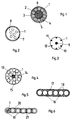
- FIG. 1 shows the structural design of an individual element 1 constructed according to the invention, which consists of a carrier element 2, for example an elongated profile of circular cross section made of a glass fiber reinforced plastic material, and in this way has a particularly high compression protection for the optical fibers 3.
- a carrier element 2 for example an elongated profile of circular cross section made of a glass fiber reinforced plastic material, and in this way has a particularly high compression protection for the optical fibers 3.
- These fibers 3 made of an inner multi-layer glass core 4 and an outer single or multi-layer covering (primary coating and / or secondary coating) are roped onto the carrier element 2 and fixed in the selected spatial association with one another by the layer 6.
- This layer 6 can be a hot melt adhesive based on polyamide, this adhesive is mechanically easy to remove from the fibers, and in the applied state it also forms a cushion layer to protect the fibers 3 from external mechanical stress.
- the diameter of such a single element 1 is extremely small, in the selected embodiment with eight stranded optical fibers, the diameter is less than 1 mm.
- the individual element is extremely stable and therefore suitable for being inserted or roped in any cable construction.
- these individual elements can be removed from the outgoing cable at branch points and used as so-called house connection lines. Due to the special arrangement of the optical fibers on the tensile and / or compressive support element, there is no need for complex sheath constructions to protect the optical fibers.
- FIG. 2 shows an exemplary embodiment of the invention in which the solution according to the invention shown in FIG. 1 is combined with an outer jacket tube.
- the surrounding protective tube 7 which is made of plastic, but can also be made of metal.
- the individual elements are loosely guided in the protective tube, the space between the inner wall of the protective tube 7 and the surface of each individual element 1 can be filled with a sealing compound which is designed so that the free movement of the individual elements 1 within the protective tube 7 is basically maintained remains.
- FIG. 3 shows a construction for receiving optical fibers in the form of a star 10 having a tensile core 9 made of a suitable plastic material.
- Grooves 11 extending longitudinally or helically in the longitudinal direction or with alternating direction of impact serve with their peripheral surfaces 12 to protect the individual element (s) 1 constructed in accordance with FIG. 1.
- FIG. 4 Another possibility according to the invention is shown in FIG. 4, here individual elements 1 corresponding to FIG. 1 are stranded around a central core 13 with so-called Blind strands 14, and a reinforcement from z. B. high tensile threads or yarns 15.
- the individual elements in FIG. 4 can also be summarized as a bundle and such bundles can then be accommodated in the grooves 11 of the star-shaped carrier body 10 in accordance with FIG. 3 or inside the protective tube 7 or As shown in FIG. 5 in one embodiment, surrounded by a common protective sheath, so that a flat cable construction is created.
- the cores 16 guided in parallel can also be only individual elements corresponding to FIG. 1, which are held securely by the surrounding surfaces of the common jacket 17. Notches 18 in the jacket 17 can serve to facilitate separation of the wires for the purpose of connection.
- FIG. 5 shows a construction of a flat cable similar to the exemplary embodiment corresponding to FIG. 6.
- B. three individual elements 1 according to FIG. 1 combined to form a core 19, each core 19 is surrounded by a jacket 20 made of a suitable plastic material, the jackets of the individual wires being interconnected by webs 21, for example made of the same material as the jacket 20 are.
- the webs 21 serve to facilitate the separation of the wires 19 from one another and thus to improve the assembly process in the production of connecting lines.
- the flat cable constructions shown in FIGS. 5 and 6 can of course also contain additional tension elements, for example the outermost of the wires 16 or 19 can be replaced by tension-resistant strands.
Landscapes
- Physics & Mathematics (AREA)
- General Physics & Mathematics (AREA)
- Optics & Photonics (AREA)
- Engineering & Computer Science (AREA)
- Manufacturing & Machinery (AREA)
- Ropes Or Cables (AREA)
- Insulated Conductors (AREA)
Applications Claiming Priority (2)
| Application Number | Priority Date | Filing Date | Title |
|---|---|---|---|
| DE4228956A DE4228956A1 (de) | 1992-08-31 | 1992-08-31 | Optisches Kabel |
| DE4228956 | 1992-08-31 |
Publications (2)
| Publication Number | Publication Date |
|---|---|
| EP0591618A2 true EP0591618A2 (fr) | 1994-04-13 |
| EP0591618A3 EP0591618A3 (en) | 1996-03-20 |
Family
ID=6466845
Family Applications (1)
| Application Number | Title | Priority Date | Filing Date |
|---|---|---|---|
| EP93109602A Ceased EP0591618A3 (en) | 1992-08-31 | 1993-06-16 | Fiber optic cable |
Country Status (2)
| Country | Link |
|---|---|
| EP (1) | EP0591618A3 (fr) |
| DE (1) | DE4228956A1 (fr) |
Families Citing this family (3)
| Publication number | Priority date | Publication date | Assignee | Title |
|---|---|---|---|---|
| DE19624967C2 (de) * | 1996-06-22 | 1998-07-02 | Alcatel Kabel Ag | Optische Ader |
| DE19744937A1 (de) * | 1997-10-10 | 1999-04-15 | Cit Alcatel | Optisches Element mit verklebten Einheiten |
| DE102006059422A1 (de) * | 2006-12-15 | 2008-06-19 | CCS Technology, Inc., Wilmington | Optisches Kabel mit Querdruckfestigkeit |
Family Cites Families (6)
| Publication number | Priority date | Publication date | Assignee | Title |
|---|---|---|---|---|
| GB2179072B (en) * | 1985-08-16 | 1988-06-29 | Stc Plc | Optical fibre cables |
| JPS62181906U (fr) * | 1986-05-10 | 1987-11-18 | ||
| DE3637603A1 (de) * | 1986-11-05 | 1988-05-19 | Standard Elektrik Lorenz Ag | Zugfestes, optisches kabel |
| JPH01138520A (ja) * | 1987-11-26 | 1989-05-31 | Sumitomo Electric Ind Ltd | 光ファイバ心線 |
| GB8908446D0 (en) * | 1989-04-14 | 1989-06-01 | Bicc Plc | Optical cable |
| US5166998A (en) * | 1992-02-21 | 1992-11-24 | Siecor Corporation | Optical ribbon cable component |
-
1992
- 1992-08-31 DE DE4228956A patent/DE4228956A1/de not_active Ceased
-
1993
- 1993-06-16 EP EP93109602A patent/EP0591618A3/de not_active Ceased
Also Published As
| Publication number | Publication date |
|---|---|
| DE4228956A1 (de) | 1994-03-03 |
| EP0591618A3 (en) | 1996-03-20 |
Similar Documents
| Publication | Publication Date | Title |
|---|---|---|
| DE69402962T2 (de) | Faseroptisches kabel mit optische fasern enthaltende schutzröhren und zugehöriges herstellungsverfahren | |
| DE2701631C2 (de) | Optisch leitendes Element | |
| DE69010544T2 (de) | Optisches Kabel. | |
| DE69527112T2 (de) | Wasserblockierendes ungefülltes Einzelrohrkabel | |
| DE2732376A1 (de) | Lichtleiterkabel | |
| EP0874262A2 (fr) | Câble optique et procédé de fabrication d'un câble optique | |
| DE2854746A1 (de) | Optisches kabel | |
| DE3932251A1 (de) | Optisches kabel mit in kammern angeordneten bandleitungen | |
| EP0834755A2 (fr) | Câble ou élément optique | |
| DE3833492C2 (de) | Vorrichtung und Verfahren zum Aufteilen von Lichtwellenleitern eines optischen Kabels | |
| EP0042996A2 (fr) | Câble d'information optique autoportant | |
| DE2511019A1 (de) | Grundelement zum aufbau optischer kabel | |
| DE3526823A1 (de) | Element mit mehreren lichtwellenleitern | |
| DE3608309C2 (fr) | ||
| EP0591618A2 (fr) | Câble à fibre optique | |
| DE29620962U1 (de) | Optisches Kabel | |
| DE29520915U1 (de) | Nachrichtenkabel | |
| DE4211489A1 (de) | Optisches Übertragungselement | |
| DE2911421A1 (de) | Lichtleiteranordnung | |
| DE29518024U1 (de) | Nachrichtenkabel | |
| EP0677759A1 (fr) | Câble optique comprenant des faisceaux résistant aux traction et compression | |
| EP0477416B1 (fr) | Câble optique | |
| EP0416207B1 (fr) | Câble optique | |
| EP0211107B1 (fr) | Câble guide d'ondes non métallique avec une structure centrale | |
| EP0602447B1 (fr) | Câble optique |
Legal Events
| Date | Code | Title | Description |
|---|---|---|---|
| PUAI | Public reference made under article 153(3) epc to a published international application that has entered the european phase |
Free format text: ORIGINAL CODE: 0009012 |
|
| AK | Designated contracting states |
Kind code of ref document: A2 Designated state(s): AT CH DE ES FR GB IT LI NL |
|
| PUAL | Search report despatched |
Free format text: ORIGINAL CODE: 0009013 |
|
| AK | Designated contracting states |
Kind code of ref document: A3 Designated state(s): AT CH DE ES FR GB IT LI NL |
|
| 17P | Request for examination filed |
Effective date: 19960210 |
|
| 17Q | First examination report despatched |
Effective date: 19970930 |
|
| STAA | Information on the status of an ep patent application or granted ep patent |
Free format text: STATUS: THE APPLICATION HAS BEEN REFUSED |
|
| 18R | Application refused |
Effective date: 19990221 |