EP0591620A1 - Batterie-Energieversorgungsanlage - Google Patents
Batterie-Energieversorgungsanlage Download PDFInfo
- Publication number
- EP0591620A1 EP0591620A1 EP93110143A EP93110143A EP0591620A1 EP 0591620 A1 EP0591620 A1 EP 0591620A1 EP 93110143 A EP93110143 A EP 93110143A EP 93110143 A EP93110143 A EP 93110143A EP 0591620 A1 EP0591620 A1 EP 0591620A1
- Authority
- EP
- European Patent Office
- Prior art keywords
- load
- power supply
- solar cell
- power
- battery power
- Prior art date
- Legal status (The legal status is an assumption and is not a legal conclusion. Google has not performed a legal analysis and makes no representation as to the accuracy of the status listed.)
- Granted
Links
Images



Classifications
-
- H—ELECTRICITY
- H02—GENERATION; CONVERSION OR DISTRIBUTION OF ELECTRIC POWER
- H02J—ELECTRIC POWER NETWORKS; CIRCUIT ARRANGEMENTS OR SYSTEMS FOR SUPPLYING OR DISTRIBUTING ELECTRIC POWER; SYSTEMS FOR STORING ELECTRIC ENERGY
- H02J4/00—Circuit arrangements for mains or distribution networks not specified as AC or DC; Circuit arrangements for mains or distribution networks combining AC and DC sections or sub-networks
- H02J4/20—Networks integrating separated AC and DC power sections
- H02J4/25—Networks integrating separated AC and DC power sections for transfer of electric power between AC and DC networks, e.g. for supplying the DC section within a load from an AC mains system
-
- H—ELECTRICITY
- H02—GENERATION; CONVERSION OR DISTRIBUTION OF ELECTRIC POWER
- H02J—ELECTRIC POWER NETWORKS; CIRCUIT ARRANGEMENTS OR SYSTEMS FOR SUPPLYING OR DISTRIBUTING ELECTRIC POWER; SYSTEMS FOR STORING ELECTRIC ENERGY
- H02J13/00—Circuit arrangements for providing remote monitoring or remote control of equipment in a power distribution network
- H02J13/13—Circuit arrangements for providing remote monitoring or remote control of equipment in a power distribution network characterised by the transmission of data to equipment in the power network
- H02J13/1331—Circuit arrangements for providing remote monitoring or remote control of equipment in a power distribution network characterised by the transmission of data to equipment in the power network using wireless data transmission
-
- H—ELECTRICITY
- H02—GENERATION; CONVERSION OR DISTRIBUTION OF ELECTRIC POWER
- H02J—ELECTRIC POWER NETWORKS; CIRCUIT ARRANGEMENTS OR SYSTEMS FOR SUPPLYING OR DISTRIBUTING ELECTRIC POWER; SYSTEMS FOR STORING ELECTRIC ENERGY
- H02J13/00—Circuit arrangements for providing remote monitoring or remote control of equipment in a power distribution network
- H02J13/18—Circuit arrangements for providing remote monitoring or remote control of equipment in a power distribution network characterised by the remotely-controlled equipment, e.g. converters or transformers
- H02J13/333—Circuit arrangements for providing remote monitoring or remote control of equipment in a power distribution network characterised by the remotely-controlled equipment, e.g. converters or transformers the equipment forming part of substations
-
- H—ELECTRICITY
- H02—GENERATION; CONVERSION OR DISTRIBUTION OF ELECTRIC POWER
- H02J—ELECTRIC POWER NETWORKS; CIRCUIT ARRANGEMENTS OR SYSTEMS FOR SUPPLYING OR DISTRIBUTING ELECTRIC POWER; SYSTEMS FOR STORING ELECTRIC ENERGY
- H02J3/00—Circuit arrangements for AC mains or AC distribution networks
- H02J3/38—Arrangements for feeding a single network from two or more generators or sources in parallel; Arrangements for feeding already energised networks from additional generators or sources in parallel
- H02J3/381—Dispersed generators
-
- H—ELECTRICITY
- H02—GENERATION; CONVERSION OR DISTRIBUTION OF ELECTRIC POWER
- H02J—ELECTRIC POWER NETWORKS; CIRCUIT ARRANGEMENTS OR SYSTEMS FOR SUPPLYING OR DISTRIBUTING ELECTRIC POWER; SYSTEMS FOR STORING ELECTRIC ENERGY
- H02J7/00—Circuit arrangements for charging or discharging batteries or for supplying loads from batteries
- H02J7/02—Circuit arrangements for charging or discharging batteries or for supplying loads from batteries for charging batteries from AC mains by converters
-
- H—ELECTRICITY
- H02—GENERATION; CONVERSION OR DISTRIBUTION OF ELECTRIC POWER
- H02J—ELECTRIC POWER NETWORKS; CIRCUIT ARRANGEMENTS OR SYSTEMS FOR SUPPLYING OR DISTRIBUTING ELECTRIC POWER; SYSTEMS FOR STORING ELECTRIC ENERGY
- H02J7/00—Circuit arrangements for charging or discharging batteries or for supplying loads from batteries
- H02J7/34—Parallel operation in networks using both storage and other DC sources, e.g. providing buffering
- H02J7/35—Parallel operation in networks using both storage and other DC sources, e.g. providing buffering with light sensitive cells
-
- H—ELECTRICITY
- H02—GENERATION; CONVERSION OR DISTRIBUTION OF ELECTRIC POWER
- H02J—ELECTRIC POWER NETWORKS; CIRCUIT ARRANGEMENTS OR SYSTEMS FOR SUPPLYING OR DISTRIBUTING ELECTRIC POWER; SYSTEMS FOR STORING ELECTRIC ENERGY
- H02J2101/00—Supply or distribution of decentralised, dispersed or local electric power generation
- H02J2101/20—Dispersed power generation using renewable energy sources
- H02J2101/22—Solar energy
- H02J2101/24—Photovoltaics
-
- Y—GENERAL TAGGING OF NEW TECHNOLOGICAL DEVELOPMENTS; GENERAL TAGGING OF CROSS-SECTIONAL TECHNOLOGIES SPANNING OVER SEVERAL SECTIONS OF THE IPC; TECHNICAL SUBJECTS COVERED BY FORMER USPC CROSS-REFERENCE ART COLLECTIONS [XRACs] AND DIGESTS
- Y02—TECHNOLOGIES OR APPLICATIONS FOR MITIGATION OR ADAPTATION AGAINST CLIMATE CHANGE
- Y02E—REDUCTION OF GREENHOUSE GAS [GHG] EMISSIONS, RELATED TO ENERGY GENERATION, TRANSMISSION OR DISTRIBUTION
- Y02E10/00—Energy generation through renewable energy sources
- Y02E10/50—Photovoltaic [PV] energy
- Y02E10/56—Power conversion systems, e.g. maximum power point trackers
-
- Y—GENERAL TAGGING OF NEW TECHNOLOGICAL DEVELOPMENTS; GENERAL TAGGING OF CROSS-SECTIONAL TECHNOLOGIES SPANNING OVER SEVERAL SECTIONS OF THE IPC; TECHNICAL SUBJECTS COVERED BY FORMER USPC CROSS-REFERENCE ART COLLECTIONS [XRACs] AND DIGESTS
- Y02—TECHNOLOGIES OR APPLICATIONS FOR MITIGATION OR ADAPTATION AGAINST CLIMATE CHANGE
- Y02E—REDUCTION OF GREENHOUSE GAS [GHG] EMISSIONS, RELATED TO ENERGY GENERATION, TRANSMISSION OR DISTRIBUTION
- Y02E40/00—Technologies for an efficient electrical power generation, transmission or distribution
- Y02E40/70—Smart grids as climate change mitigation technology in the energy generation sector
-
- Y—GENERAL TAGGING OF NEW TECHNOLOGICAL DEVELOPMENTS; GENERAL TAGGING OF CROSS-SECTIONAL TECHNOLOGIES SPANNING OVER SEVERAL SECTIONS OF THE IPC; TECHNICAL SUBJECTS COVERED BY FORMER USPC CROSS-REFERENCE ART COLLECTIONS [XRACs] AND DIGESTS
- Y02—TECHNOLOGIES OR APPLICATIONS FOR MITIGATION OR ADAPTATION AGAINST CLIMATE CHANGE
- Y02E—REDUCTION OF GREENHOUSE GAS [GHG] EMISSIONS, RELATED TO ENERGY GENERATION, TRANSMISSION OR DISTRIBUTION
- Y02E60/00—Enabling technologies; Technologies with a potential or indirect contribution to GHG emissions mitigation
-
- Y—GENERAL TAGGING OF NEW TECHNOLOGICAL DEVELOPMENTS; GENERAL TAGGING OF CROSS-SECTIONAL TECHNOLOGIES SPANNING OVER SEVERAL SECTIONS OF THE IPC; TECHNICAL SUBJECTS COVERED BY FORMER USPC CROSS-REFERENCE ART COLLECTIONS [XRACs] AND DIGESTS
- Y02—TECHNOLOGIES OR APPLICATIONS FOR MITIGATION OR ADAPTATION AGAINST CLIMATE CHANGE
- Y02P—CLIMATE CHANGE MITIGATION TECHNOLOGIES IN THE PRODUCTION OR PROCESSING OF GOODS
- Y02P90/00—Enabling technologies with a potential contribution to greenhouse gas [GHG] emissions mitigation
- Y02P90/50—Energy storage in industry with an added climate change mitigation effect
-
- Y—GENERAL TAGGING OF NEW TECHNOLOGICAL DEVELOPMENTS; GENERAL TAGGING OF CROSS-SECTIONAL TECHNOLOGIES SPANNING OVER SEVERAL SECTIONS OF THE IPC; TECHNICAL SUBJECTS COVERED BY FORMER USPC CROSS-REFERENCE ART COLLECTIONS [XRACs] AND DIGESTS
- Y04—INFORMATION OR COMMUNICATION TECHNOLOGIES HAVING AN IMPACT ON OTHER TECHNOLOGY AREAS
- Y04S—SYSTEMS INTEGRATING TECHNOLOGIES RELATED TO POWER NETWORK OPERATION, COMMUNICATION OR INFORMATION TECHNOLOGIES FOR IMPROVING THE ELECTRICAL POWER GENERATION, TRANSMISSION, DISTRIBUTION, MANAGEMENT OR USAGE, i.e. SMART GRIDS
- Y04S10/00—Systems supporting electrical power generation, transmission or distribution
- Y04S10/12—Monitoring or controlling equipment for energy generation units, e.g. distributed energy generation [DER] or load-side generation
- Y04S10/123—Monitoring or controlling equipment for energy generation units, e.g. distributed energy generation [DER] or load-side generation the energy generation units being or involving renewable energy sources
-
- Y—GENERAL TAGGING OF NEW TECHNOLOGICAL DEVELOPMENTS; GENERAL TAGGING OF CROSS-SECTIONAL TECHNOLOGIES SPANNING OVER SEVERAL SECTIONS OF THE IPC; TECHNICAL SUBJECTS COVERED BY FORMER USPC CROSS-REFERENCE ART COLLECTIONS [XRACs] AND DIGESTS
- Y04—INFORMATION OR COMMUNICATION TECHNOLOGIES HAVING AN IMPACT ON OTHER TECHNOLOGY AREAS
- Y04S—SYSTEMS INTEGRATING TECHNOLOGIES RELATED TO POWER NETWORK OPERATION, COMMUNICATION OR INFORMATION TECHNOLOGIES FOR IMPROVING THE ELECTRICAL POWER GENERATION, TRANSMISSION, DISTRIBUTION, MANAGEMENT OR USAGE, i.e. SMART GRIDS
- Y04S40/00—Systems for electrical power generation, transmission, distribution or end-user application management characterised by the use of communication or information technologies, or communication or information technology specific aspects supporting them
- Y04S40/12—Systems for electrical power generation, transmission, distribution or end-user application management characterised by the use of communication or information technologies, or communication or information technology specific aspects supporting them characterised by data transport means between the monitoring, controlling or managing units and monitored, controlled or operated electrical equipment
- Y04S40/126—Systems for electrical power generation, transmission, distribution or end-user application management characterised by the use of communication or information technologies, or communication or information technology specific aspects supporting them characterised by data transport means between the monitoring, controlling or managing units and monitored, controlled or operated electrical equipment using wireless data transmission
-
- Y—GENERAL TAGGING OF NEW TECHNOLOGICAL DEVELOPMENTS; GENERAL TAGGING OF CROSS-SECTIONAL TECHNOLOGIES SPANNING OVER SEVERAL SECTIONS OF THE IPC; TECHNICAL SUBJECTS COVERED BY FORMER USPC CROSS-REFERENCE ART COLLECTIONS [XRACs] AND DIGESTS
- Y10—TECHNICAL SUBJECTS COVERED BY FORMER USPC
- Y10S—TECHNICAL SUBJECTS COVERED BY FORMER USPC CROSS-REFERENCE ART COLLECTIONS [XRACs] AND DIGESTS
- Y10S136/00—Batteries: thermoelectric and photoelectric
- Y10S136/291—Applications
- Y10S136/293—Circuits
-
- Y—GENERAL TAGGING OF NEW TECHNOLOGICAL DEVELOPMENTS; GENERAL TAGGING OF CROSS-SECTIONAL TECHNOLOGIES SPANNING OVER SEVERAL SECTIONS OF THE IPC; TECHNICAL SUBJECTS COVERED BY FORMER USPC CROSS-REFERENCE ART COLLECTIONS [XRACs] AND DIGESTS
- Y10—TECHNICAL SUBJECTS COVERED BY FORMER USPC
- Y10S—TECHNICAL SUBJECTS COVERED BY FORMER USPC CROSS-REFERENCE ART COLLECTIONS [XRACs] AND DIGESTS
- Y10S323/00—Electricity: power supply or regulation systems
- Y10S323/906—Solar cell systems
Definitions
- the present invention relates to a battery power supply system, and more particularly to an inexpensive battery power supply system which may quickly release a reverse charge phenomenon.
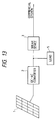
- FIG. 13 A DC power generated by a solar cell is converted to an AC power by a DC-AC inverter 2 and it is supplied to a load 5.
- the commercial power is supplied to the load 5 through a break device 3, which disconnects the solar generation system from the system line in response to short circuiting accident in the system or an accident of the commercial system. In most cases, it stops the DC-AC inverter 2.
- the power generated by the solar cell is in excess in daytime.
- the flow of the excess power to the power system is called a "reverse current".
- the reverse current By the reverse current, the electricity generated by the solar cell can be used without waste.
- Such a reverse current type solar cell generation system would be an ideal manner of use of the solar cell.
- a problem of "reverse charge phenomenon" which is inherent to the reverse current system has not yet been solved.
- the "reverse charge phenomenon” may occur when the quantity of generation by the solar cell generation system and the power consumption of a load connected thereto are substantially equal. In such a case, even if the electricity of the commercial power supply system is stopped or it stops by some cause, the solar cell generation system cannot detect the stop of the commercial power system and the solar cell generation system continues the independent operation. As a result, lines which are not to be active are charged and a risk occurs in a maintenance operation of the lines. Further, when the commercial power system is reclosed, the commercial power system and the solar cell generation system are not in synchronism and an excess current is generated and the reclosure may fail. When many solar cell generation systems are used in future, the "reverse charge phenomenon" may occur over a wide area.
- a "transfer break system” is used to avoid the reverse charge status.
- a break device is actuated by a break signal from a host substation to stop the system.
- it is necessary to install a communication line to each of the solar cell generation systems, and it is not feasible because of a huge amount of cost.
- a telephone line may be used as the communication line for the transfer break.
- a cost to install the communication line for each system may be significantly reduced.
- the reverse charge phenomenon may possibly occur over a wide area. In such a case, all or most of the solar cell generation systems in the area of the reverse charge phenomenon must be broken.
- a telephone line system which assigns the number to each of the users is not appropriate.
- telephone calls must be made at least one hundred times. Assuming that one user can be accessed in five seconds, it takes 500 seconds or more than eight minutes.
- the present invention provides a battery power supply system comprising a battery power supply, a DC-AC inverter for converting a DC output of the battery power supply to an AC output to supply it to a load, a break device electrically connected between an AC power system and the load, wireless communication means, and break device control means for controlling the conduction/break of the break device in accordance with information derived from the wireless communication means.
- the frequency of the wireless communication means is around a middle wave broadcast band or a TV broadcast band.
- the break device control means includes time information control means for controlling based on time information and identification information control means for controlling based on identification information.
- the present invention also provides a battery power supply system comprising a DC-AC inverter for converting a DC output of a battery power supply to an AC output to supply it to a load, first power measurement means for measuring the output of the DC-AC inverter, second power measurement means for measuring an input power from a power system for powering to the load or a power consumption of the load, a dummy load device electrically connected between the power system and the load for controlling the amount of load, and control means for controlling the amount of load of the dummy load device based on the measurements of the first and second power measurement means.
- the dummy load includes a secondary battery.
- the break device is controlled by the reception result of the wireless communication means or the reverse charge of the inverter is prevented.
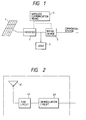
- Fig. 1 shows a configuration of a battery power supply system of the present invention.
- Fig. 2 shows a configuration of wireless communication means used in the battery power supply system of the present invention.
- Fig. 3 shows an embodiment of the wireless communication means used in the battery power supply system of the present invention.
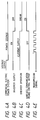
- Figs. 4A-4E show timing charts of operations of the embodiment.
- Fig. 5 shows another embodiment of the wireless communication means used in the battery power supply system of the present invention.
- Fig. 6 shows a system for recovering a power after a predetermined time interval by using time information, used in the battery power supply system of the present invention.
- Fig. 7 shows a system for recording break operation by using time information and sender identification information, used in the battery power supply system of the present invention.
- Fig. 8 shows a system combined with the system of the present invention.
- Fig. 9 shows a battery power supply system having a reverse current and reverse charge prevention device of the present invention.
- Fig. 10 shows an operation chart of the reverse current and reverse charge prevention device used in the battery power supply system of the present invention.
- Fig. 11 shows another embodiment of the battery power supply system having the reverse current and reverse charge prevention device of the present invention.
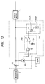
- Fig. 12 shows a further embodiment of the battery power supply system having the reverse current and reverse charge prevention device of the present invention.
- Fig. 13 shows a configuration of a prior art battery power supply system.
- FIG. 1 An embodiment of the battery power supply system of the present invention is shown in Fig. 1.
- a solar cell array 1 having a plurality of solar cell modules converts sun shine to a DC power.
- a photo-electromotive device such as single crystal silicon, poly-crystalline silicon, amorphous silicon or a combination thereof may be used.
- a DC-AC inverter 2 converts the DC power from the solar cell array to an AC power and supplies it to a load 5.
- the DC-AC inverter 2 may be a self-excited type or a separately excited type, and among others, a PWM self-excited inverter which uses IGBT, power MOSFET and power transistor as switching devices is preferable.
- the inverter includes gate control means for the switching devices to start and stop the inverter.
- a break device 3 having control means therein mechanically separates a commercial power system and the solar cell generation system.
- Wireless communication means 4 is connected to the break device 3 and the control means in the DC-AC inverter 2.
- An embodiment of the wireless communication means 4 is shown in Fig. 2.
- numeral 41 denotes an antenna which may be a bar antenna, a Yagi antenna, a parabola antenna or a rod antenna depending on a frequency and electric field intensity of an electromagnetic wave used.
- Numeral 42 denotes a tuning circuit for receiving a target frequency.
- Numeral 43 denotes a demodulation circuit which extracts a signal from the received electromagnetic wave.
- the frequency for the communication may be any frequency from a long wave to an UHF but a large antenna is principally needed for a frequency shorter than a relatively long short wave. In order to receive a frequency band of shorter than the short wave by a small antenna, it is necessary to transmit as strong electromagnetic wave as that of a broadcast station.
- the signal used for the communication may be a coded signal which uses the on/off of the electromagnetic wave or a coded signal which uses frequency deviation.
- a signal in an audio frequency band may be used.
- the break signal preferably includes at least an ID signal for specifying a region and operation command information.
- the ID information (code number) may be assigned to a region having several hundreds or more users. By assigning one ID information to many users, more solar cell generation systems may be broken by one signal transmission. For example, one ID number code may be assigned throughout Japan and the break signal may be transmitted by using a BS system so that the solar cell generation systems throughout Japan can be simultaneously broken. In actual, the assignment region may be determined while taking the power transmission system into account. Time information or sender identification information may be further added to attain fine operation.
- "recovery time” information may be transmitted so that the solar cell generation system can be restarted at any desired time by a timer circuit 56 after the recovery of the power failure.
- "start time” and “stop time” it is possible to activate the system for only a desired time period of the sender.
- the time of break and the person who broke can be recorded in a memory 58 by a time signal detector 59 and a sender detector 57. Accordingly, it is possible to determine whether a controller (electric power service company) who controls many regions has broken because of the reverse charge or an operator has broken for a work on site, and can grasp the risk condition of the reverse charge in the region.
- a controller electric power service company
- the wireless communication means need not have transmission means but the object of the present invention can be achieved only by the reception means.
- the solar cell array 1 comprises 20 amorphous silicon solar cell modules (rated voltage 12 volts, rated power 22 watts) to form 240 V - 440 W solar cell array.
- the inverter 2 is a self-excited transistor inverter (rated output 50 W, 100 V).
- the break device 3 is a combination of a sequencer and a transducer which breaks the commercial power system when an AC excess current or excess voltage occurs, as shown in Fig. 1.
- the wireless communication means 4 is constructed as shown in Fig. 3.
- the antenna 44 is a middle wave broadcast bar antenna having a receiving frequency of 1630 KHz.
- the received signal is detected by a diode 45, converted to a pulse signal by a transistor 46, and it is supplied to a pulse counter 47.
- An output of the pulse counter 47 is compared with an ID number stored in an ID ROM 48 by a code comparator 49.
- the code comparator 49 produces a control output.
- the control output is supplied to the inverter 2 and the control unit in the break device 3. Since only the break operation is carried out in the present embodiment, the ID information and the operation command information are shared.
- the ID number is 5. Thus, when five pulses are inputted, the count "5" in the pulse counter 47 and the value from the ID ROM 48 (the ID number which is equal to 5) coincide so that the code comparator 49 produces the control output to break the power.
- the load 5 comprises four 100 watts bulbs. The procedures of operation are shown below.
- FIG. 4A - 4E Operation charts are shown in Figs. 4A - 4E.
- the control output is ON when five pulses have been applied and the inverter and the break device are actuated to stop the solar cell generation system.
- the solar cell array 1, the inverter 2 and the break device 3 are of the same configuration as those of Fig. 1, and the wireless communication means 4 is constructed as shown in Fig. 5.
- a code is transmitted in an audio frequency band by using a modem for a telephone line.
- the modulation of the electromagnetic wave is done by a frequency modulation at frequency of 140 MHz.
- the antenna 50 may be an inexpensive TV broadcast Yagi antenna.
- the signal received by the antenna 50 is applied to an FM demodulator 51 which demodulates ID signal comprising a code of the audio frequency band.
- the communication frequency is 420 MHz and three solar cell generation systems of the same configuration as that used in the embodiment 2 are parallelly connected to form a solar cell generation system shown in Fig. 8.
- the antenna is a UHF TV antenna.
- ID information "A" is assigned to two (solar cell generation systems 1 and 2) of the three solar cell generation systems and ID information "B" is assigned to the remaining one (solar cell generation system 3).
- the load is adjusted to singly operate the solar cell generation system, and the ID code "A" was transmitted.
- the two systems 1 and 2 having the coincident ID code stopped the operation, and immediately thereafter, the system 3 having the ID code "B" assigned thereto stopped the operation. This is because an excess voltage occurs in the last system 3 and the break operation is caused by the excess voltage. In this manner, when a portion of the system does not operate, it affects to all of the reverse charge system so that other solar cell generation systems are blocked. Thus, the system is highly safe.
- the solar cell generation system comprises the solar cell array 1, the DC-AC inverter 2, the commercial power system break device 3 and the wireless communication means 3, and the break device 3 is controlled its conduction and break by the wireless communication means 4. It offers the following effects:
- FIG. 9 An embodiment of the solar cell generation system which uses the reverse current and reverse charge prevention device of the present invention is shown in Fig. 9.
- a portion enclosed by broken lines is the reverse current and reverse charge prevention device of the present invention.
- a solar cell array 1 comprising a plurality of solar cell modules converts sun shine to a DC power.
- a DC-AC inverter 2 converts the DC power from the solar cell array to an AC power.
- the inverter 2 may be self-excited type or separately excited type, and a PWM self-excited inverter which uses IGBT, power MOSFET and power transistor as switching devices is preferable.
- the inverter includes gate control means for the switching devices to start and stop the inverter.
- a maximum power tracking function for the solar cell is also provided so that a maximum available power can always be taken out of the solar cell array.
- a break device 3 mechanically separates the commercial power system from the solar cell system.
- Numeral 4 denote a load such as a user, and specifically it is a home electric equipment.
- Numeral 101 denotes power measurement means for measuring the output of the inverter 2. It may be a power meter or a combination of an ammeter and a volt meter. In the latter case, the measurements are multiplied to each other to calculate an integration in a period of the commercial power system frequency to determine the power.
- the measurement means may be a current transformer, a voltage transformer or a digital power meter.
- Numeral 102 denotes power measurement means for measuring an input power from the commercial power system. It may be a power meter or a combination of an ammeter and a volt meter, as the above power measurement means is.
- Numeral 103 denote a control unit (controller) which receives the measurement outputs from the power measurement means 101 and 102 and processes them to produce a control output.
- the control means may be a programmable controller.
- Numeral 104 denotes a dummy load for controlling the amount of load. It may be an electronic load device, a combination of a resistive load and a slidac transformer, a combination of a resistive load and a triac device, a plurality of resistors selectable by relays or a secondary battery.
- the control unit 103 continuously monitors the output of the inverter 2 and the power consumption of the load 4 by the two power meters 101 and 102 and controls the dummy load 104 such that the dummy load 104 consumes the output of the inverter 2 to maintain the minimum receiving power when a difference between the power consumption of the load 4 and the output of the inverter 2 becomes smaller than the minimum receiving power.
- the inverter output and the power consumption of the load are continuously monitored, and when the difference between the power consumption of the load and the inverter output is larger than the minimum receiving power, the control command is issued to the load to consume more power than the minimum receiving power. As a result, the output from the inverter is totally consumed in the premises of the user and the reverse current and reverse charge to the system is prevented.
- a solar cell generation system which uses the device of the present invention is constructed as shown in Fig. 9.
- the solar cell array 1 comprises 20 amorphous silicon solar cell modules (rated voltage 12 V, rated power 22 W) to form an array of 240 V, 440 W.
- the inverter 2 is a self-excited transistor inverter (rated output 500 W, 100 V, operable in a reverse correct mode).
- the break device 3 is a combination of a sequencer and a transducer which breaks the commercial system when an excess current or excess voltage occurs.
- the load 4 comprises three 100 W bulbs.
- a minimum receiving power is 10 W.
- the power measurement means 101 is a power meter which measures the output power of the inverter and produces a digital output
- the power measurement means 102 is a power meter which measures the power consumption of the load and produces a digital output.
- the measurement outputs are supplied to a measurement control computer which serves as the control unit 103, through a GPIB interface.
- the control output of the control unit 103 is supplied to an electronic load device which serves as the dummy load 104, through the GPIB interface.
- FIG. 10 An operation chart of the reverse current and reverse charge prevention device in the solar cell generation system of the present invention on a fine weather day is shown in Fig. 10.
- An abscissa represents a time and an ordinate represents a power.
- the inverter output exceeds 290 W and the electronic load device starts to operate.
- the receiving power is kept at a minimum receiving power 10 W as shown by a solid line B so that the reverse current and the reverse charge are prevented.
- the power shown by a broken line C in Fig. 10 shows the reverse current power created when the present device is not used.
- the solar cell array 1, the inverter 2, the break device 3 and the load 4 are of the same construction as those of the embodiment 5 and the reverse current and reverse charge prevention device is constructed as shown in Fig. 11.
- CT Current transformers
- PT potentio-transformers
- PT potentio-transformers
- the dummy load 104 comprises eight 30 W bulbs and eight relays serially connected thereto. Drive inputs of the relays are connected to other general purpose parallel port of the control unit 103.
- the dummy load 104 has a power consumption which is an integer multiple of 30 W.
- the dummy load 104 assumes only the integer multiple of 30 W, the receiving power is little bit larger than that of the embodiment 5.
- an expensive electronic load device is not required and the control unit is compact.
- the solar cell array, the inverter, the brake device and the load are of the same construction as those of the embodiment 5 and the reverse current and reverse charge prevention device is constructed as shown in Fig. 12.
- the power measurement means 101 and 102 are power meters which produce analog measurement outputs and they are arranged to measure the inverter output and the input power from the commercial power system, respectively.
- the control unit 103 which comprises an operational amplifier.
- the operational amplifier 11 is an adder which calculates a difference between the output of the converter 2 and the power consumption of the load 4 based on the measurements of the power meters 101 and 102.
- the output of the operational amplifier 11 is supplied to a comparator 12 which compares it with a voltage 13 corresponding to the minimum receiving power, and produces an output when the difference between the power consumption of the load 4 and the output of the inverter 2 is smaller than the minimum receiving power.
- the output of the control unit 103 is either digital value "1" or "0", which drives a relay 104R in the dummy load device 104.
- a 400 W heater is connected to the relay 104R as a load.
- the receiving power is larger than that of the embodiment 6 but the configuration of the present embodiment is very simple.
- the embodiments 5-7 relate to the reverse current and reverse charge prevention device to be added to the solar cell generation system comprising the solar cell array, the DC-AC inverter which may operate in the reverse current mode, and the load. It comprises the power measurement means for measuring the output of the inverter, the power measurement means for measuring the input power from the commercial system or the power consumption of the load, the dummy load device capable of controlling the amount of load, and the control means for supplying the load control signal to the dummy load device in accordance with the measurements by the power measurement means.
- the solar cell generation system free from the reverse current and the reverse charge can be constructed by merely adding the present device as the reverse current and reverse charge prevention device, without modifying the inverter.
- the reverse charge is quickly released and the reverse current is prevented.
- a battery power supply system permits inexpensive introduction of a transfer break system to a solar cell generation system and quick release of reverse charge phenomenon.
- the battery power supply system comprises a solar cell array 1, a DC-AC inverter 2, a brake device 3 for a commercial power system, and wireless communication means 4 as control means for controlling the conduction and break of the break device based on the information derived through wireless communication.
Landscapes
- Engineering & Computer Science (AREA)
- Power Engineering (AREA)
- Charge And Discharge Circuits For Batteries Or The Like (AREA)
- Supply And Distribution Of Alternating Current (AREA)
- Inverter Devices (AREA)
- Photovoltaic Devices (AREA)
Priority Applications (1)
| Application Number | Priority Date | Filing Date | Title |
|---|---|---|---|
| EP96103083A EP0718952B1 (de) | 1992-06-26 | 1993-06-24 | Batterie-Energieversorgungsanlage |
Applications Claiming Priority (3)
| Application Number | Priority Date | Filing Date | Title |
|---|---|---|---|
| JP16968292 | 1992-06-26 | ||
| JP169682/92 | 1992-06-26 | ||
| JP16968292 | 1992-06-26 |
Related Child Applications (2)
| Application Number | Title | Priority Date | Filing Date |
|---|---|---|---|
| EP96103083A Division EP0718952B1 (de) | 1992-06-26 | 1993-06-24 | Batterie-Energieversorgungsanlage |
| EP96103083.0 Division-Into | 1993-06-24 |
Publications (2)
| Publication Number | Publication Date |
|---|---|
| EP0591620A1 true EP0591620A1 (de) | 1994-04-13 |
| EP0591620B1 EP0591620B1 (de) | 1999-09-01 |
Family
ID=15890956
Family Applications (2)
| Application Number | Title | Priority Date | Filing Date |
|---|---|---|---|
| EP96103083A Expired - Lifetime EP0718952B1 (de) | 1992-06-26 | 1993-06-24 | Batterie-Energieversorgungsanlage |
| EP93110143A Expired - Lifetime EP0591620B1 (de) | 1992-06-26 | 1993-06-24 | Batterie-Energieversorgungsanlage |
Family Applications Before (1)
| Application Number | Title | Priority Date | Filing Date |
|---|---|---|---|
| EP96103083A Expired - Lifetime EP0718952B1 (de) | 1992-06-26 | 1993-06-24 | Batterie-Energieversorgungsanlage |
Country Status (8)
| Country | Link |
|---|---|
| US (1) | US5592074A (de) |
| EP (2) | EP0718952B1 (de) |
| KR (1) | KR100201503B1 (de) |
| AT (2) | ATE188817T1 (de) |
| AU (1) | AU671455B2 (de) |
| DE (2) | DE69327594T2 (de) |
| DK (1) | DK0718952T3 (de) |
| ES (2) | ES2137208T3 (de) |
Cited By (12)
| Publication number | Priority date | Publication date | Assignee | Title |
|---|---|---|---|---|
| CN101777962A (zh) * | 2009-12-22 | 2010-07-14 | 华为技术有限公司 | 上行数据处理方法、装置和基站 |
| US7839025B2 (en) | 2006-11-27 | 2010-11-23 | Xslent Energy Technologies, Llc | Power extractor detecting a power change |
| US7960870B2 (en) | 2006-11-27 | 2011-06-14 | Xslent Energy Technologies, Llc | Power extractor for impedance matching |
| EP2337179A1 (de) * | 2009-12-21 | 2011-06-22 | SMA Solar Technology AG | Einspeisung elektrischer Energie von räumlich verteilten Energiequellen in ein Wechselstromnetz |
| US8013474B2 (en) | 2006-11-27 | 2011-09-06 | Xslent Energy Technologies, Llc | System and apparatuses with multiple power extractors coupled to different power sources |
| GB2499474A (en) * | 2012-02-14 | 2013-08-21 | Michael Joseph Clifton | Router to divert excess solar generated electricity to an immersion heater |
| CN103701094A (zh) * | 2012-10-09 | 2014-04-02 | 中电电气(南京)太阳能研究院有限公司 | 一种光伏防火防尘方法及装置 |
| CN103701093A (zh) * | 2012-10-09 | 2014-04-02 | 中电电气(南京)太阳能研究院有限公司 | 一种光伏防火断路器及光伏断路方法 |
| CN104184161A (zh) * | 2014-09-15 | 2014-12-03 | 绿源霖节能科技(天津)有限公司 | 一种用于平衡电网负荷的电池储能装置及方法 |
| CN105305475A (zh) * | 2014-05-29 | 2016-02-03 | �林昌明 | 一种适用于光储一体化发电系统的三相并网功率逆变模块 |
| US9431828B2 (en) | 2006-11-27 | 2016-08-30 | Xslent Energy Technologies | Multi-source, multi-load systems with a power extractor |
| CN110661307A (zh) * | 2018-06-29 | 2020-01-07 | 北京汉能光伏投资有限公司 | 一种充电控制方法、充电设备及太阳能充电系统 |
Families Citing this family (47)
| Publication number | Priority date | Publication date | Assignee | Title |
|---|---|---|---|---|
| TW336271B (en) * | 1995-06-13 | 1998-07-11 | Sanyo Electric Co | Solar generator and an air conditioner with such a solar generator |
| DE69738593T2 (de) * | 1996-06-24 | 2009-04-23 | Sanyo Electric Co., Ltd., Moriguchi | Stromversorgungssystem mit Systemverbindung |
| JP3352334B2 (ja) * | 1996-08-30 | 2002-12-03 | キヤノン株式会社 | 太陽電池の電力制御装置 |
| US6127797A (en) * | 1997-11-26 | 2000-10-03 | Walker; Mary Ann | Light-operated telephone and method of operation thereof |
| DE19844977A1 (de) * | 1998-09-30 | 2000-04-13 | Siemens Solar Gmbh | Schutzsystem für ein Solarmodul |
| JP2000269531A (ja) | 1999-01-14 | 2000-09-29 | Canon Inc | 太陽電池モジュール、太陽電池モジュール付き建材、太陽電池モジュール外囲体及び太陽光発電装置 |
| US6201180B1 (en) * | 1999-04-16 | 2001-03-13 | Omnion Power Engineering Corp. | Integrated photovoltaic system |
| JP2001161032A (ja) | 1999-12-01 | 2001-06-12 | Canon Inc | 系統連系パワーコンディショナ及びそれを用いた発電システム |
| JP2001314038A (ja) * | 2000-04-28 | 2001-11-09 | Mitsubishi Heavy Ind Ltd | 発電システムおよび燃料供給方法 |
| US7733069B2 (en) * | 2000-09-29 | 2010-06-08 | Canon Kabushiki Kaisha | Power converting apparatus and power generating apparatus |
| JP2002112553A (ja) | 2000-09-29 | 2002-04-12 | Canon Inc | 電力変換装置およびその制御方法、並びに、発電装置 |
| JP2002204531A (ja) | 2000-10-31 | 2002-07-19 | Canon Inc | 交流連系装置およびその制御方法 |
| JP2002318162A (ja) * | 2001-02-01 | 2002-10-31 | Canon Inc | 異常の検知方法および保護装置、並びに、温度の推定方法および推定装置 |
| JP2002233045A (ja) | 2001-02-02 | 2002-08-16 | Canon Inc | 太陽光発電システムの地絡検出のための装置及び方法 |
| JP2002252986A (ja) | 2001-02-26 | 2002-09-06 | Canon Inc | インバータ、電源システム及び電源システムにおける漏れ電流低減方法 |
| JP2003098215A (ja) * | 2001-09-26 | 2003-04-03 | Canon Inc | 電力変換システムにおける地絡検出のための装置及び方法 |
| JP2003180036A (ja) * | 2001-10-01 | 2003-06-27 | Canon Inc | 電力変換装置、電力変換システム、及び単独運転検出方法 |
| JPWO2004100337A1 (ja) * | 2003-05-07 | 2006-07-13 | 株式会社荏原電産 | 系統連系インバータを含む電源装置 |
| US6949843B2 (en) * | 2003-07-11 | 2005-09-27 | Morningstar, Inc. | Grid-connected power systems having back-up power sources and methods of providing back-up power in grid-connected power systems |
| US20120181973A1 (en) * | 2003-08-29 | 2012-07-19 | Robert Lyden | Solar array resembling natural foliage including means for wireless transmission of electric power |
| JP2005086101A (ja) * | 2003-09-10 | 2005-03-31 | Tokyo Electron Ltd | 太陽電池アレイ製造方法、太陽電池アレイ装置、太陽電池アレイ装置を備える電子機器及び電子機器システム |
| DE102004025924A1 (de) * | 2004-05-27 | 2005-12-22 | Siemens Ag | Solarwechselrichter und Photovoltaikanlage mit mehreren Solarwechselrichtern |
| US7199488B1 (en) | 2004-10-14 | 2007-04-03 | Baker David A | Telemetry power system |
| US7193872B2 (en) * | 2005-01-28 | 2007-03-20 | Kasemsan Siri | Solar array inverter with maximum power tracking |
| JP4932736B2 (ja) * | 2005-12-07 | 2012-05-16 | 株式会社三社電機製作所 | 電力回収用コンバータ |
| DE102006026661B4 (de) * | 2006-02-14 | 2008-10-09 | Diehl Ako Stiftung & Co. Kg | Photovoltaikanlage |
| CN100499312C (zh) * | 2006-05-12 | 2009-06-10 | 财团法人工业技术研究院 | 结合再生能源与无线通讯的供电及电池交换装置 |
| JP4804375B2 (ja) * | 2007-01-30 | 2011-11-02 | 三洋電機株式会社 | 系統連系装置及び系統連系システム |
| US20090000654A1 (en) | 2007-05-17 | 2009-01-01 | Larankelo, Inc. | Distributed inverter and intelligent gateway |
| US20080283118A1 (en) | 2007-05-17 | 2008-11-20 | Larankelo, Inc. | Photovoltaic ac inverter mount and interconnect |
| US7701085B2 (en) * | 2007-05-30 | 2010-04-20 | Sanyo Electric Co., Ltd. | Grid interconnection device, grid interconnection system and power control system |
| US9407093B2 (en) * | 2007-08-22 | 2016-08-02 | Maxout Renewables, Inc. | Method for balancing circuit voltage |
| TWI370551B (en) * | 2008-07-03 | 2012-08-11 | Ind Tech Res Inst | Photovoltaic electrochromic device |
| US20100006140A1 (en) * | 2008-07-14 | 2010-01-14 | Parker James L | Solar Energy System |
| US8693228B2 (en) | 2009-02-19 | 2014-04-08 | Stefan Matan | Power transfer management for local power sources of a grid-tied load |
| JP5507980B2 (ja) * | 2009-11-27 | 2014-05-28 | スパンション エルエルシー | スイッチング電源の制御回路、電子機器、及びスイッチング電源の制御方法 |
| US20110267068A1 (en) * | 2010-05-03 | 2011-11-03 | Jian Xu | Energy storage level indication circuit |
| JP5641518B2 (ja) * | 2010-07-26 | 2014-12-17 | テンパール工業株式会社 | 太陽光発電装置 |
| AT510938B1 (de) * | 2010-12-21 | 2015-03-15 | Werner Atzenhofer | Photovoltaikanlage |
| US20120065806A1 (en) * | 2011-05-06 | 2012-03-15 | General Electric Company | Method for measuring energy usage in an appliance |
| EP3120437B1 (de) * | 2014-03-19 | 2019-10-09 | Qml, Llc | Stromverwaltungsvorrichtungen und kits damit |
| CN107124039A (zh) * | 2017-06-29 | 2017-09-01 | 甘肃华兴石油工程有限责任公司 | 一种智能集成控制柜 |
| US10840707B2 (en) | 2018-08-06 | 2020-11-17 | Robert M. Lyden | Utility pole with solar modules and wireless device and method of retrofitting existing utility pole |
| US11207988B2 (en) | 2018-08-06 | 2021-12-28 | Robert M. Lyden | Electric or hybrid vehicle with wireless device and method of supplying electromagnetic energy to vehicle |
| US11588421B1 (en) | 2019-08-15 | 2023-02-21 | Robert M. Lyden | Receiver device of energy from the earth and its atmosphere |
| US11545931B2 (en) | 2019-11-10 | 2023-01-03 | Maxout Renewables, Inc. | Optimizing hybrid inverter system |
| CN111917139A (zh) * | 2020-07-10 | 2020-11-10 | 中国电力科学研究院有限公司 | 一种电网主设备可停电窗口期确定方法及系统 |
Citations (7)
| Publication number | Priority date | Publication date | Assignee | Title |
|---|---|---|---|---|
| US4360881A (en) * | 1980-07-07 | 1982-11-23 | Martinson John R | Energy consumption control system and method |
| JPS59198877A (ja) * | 1983-04-20 | 1984-11-10 | Sanyo Electric Co Ltd | 並列運転による電源装置 |
| JPS62145314A (ja) * | 1985-12-19 | 1987-06-29 | Sanyo Electric Co Ltd | 系統連系インバ−タの逆圧防止方法 |
| DE4021552A1 (de) * | 1990-07-06 | 1990-11-29 | Hoppe Michael | Verfahren einer sicherheitsabschaltung fuer in das netz einspeisende wechselrichter bei netzausfall |
| EP0415228A2 (de) * | 1989-08-21 | 1991-03-06 | Nissin Electric Company, Limited | Schaltungssteuervorrichtung zum Steuern der Schaltung eines kleinen Generators an einem Stromversorgungssystem |
| JPH04153713A (ja) * | 1990-10-17 | 1992-05-27 | Sanyo Electric Co Ltd | 双方向電力変換装置 |
| JPH0591671A (ja) * | 1991-09-26 | 1993-04-09 | Ngk Insulators Ltd | 配電系統の逆充電防止システム |
Family Cites Families (14)
| Publication number | Priority date | Publication date | Assignee | Title |
|---|---|---|---|---|
| US4333136A (en) * | 1979-11-26 | 1982-06-01 | Baker Richard H | Solar powered automatic turn-on control (SPA-TOC) unit and method |
| FR2485827A1 (fr) * | 1980-06-26 | 1981-12-31 | Aerospatiale | Procede et systeme pour la production de puissance photovoltaique |
| US4341607A (en) * | 1980-12-08 | 1982-07-27 | E:F Technology, Inc. | Solar power system requiring no active control device |
| US4404472A (en) * | 1981-12-28 | 1983-09-13 | General Electric Company | Maximum power control for a solar array connected to a load |
| JPS59149669A (ja) * | 1983-02-14 | 1984-08-27 | Toshiba Corp | 燃料電池の過電圧抑制装置 |
| JPS6121516A (ja) * | 1984-07-09 | 1986-01-30 | Hitachi Ltd | 燃料電池発電システム |
| US4794272A (en) * | 1987-01-20 | 1988-12-27 | The Aerospace Corporation | Power regulator utilizing only battery current monitoring |
| DE3725476A1 (de) * | 1987-07-31 | 1989-02-09 | Siemens Ag | Schaltungsanordnung zur speisung einer elektrischen last aus einer elektrischen energiequelle mit schwankender leistungsfaehigkeit |
| US4763014A (en) * | 1987-09-21 | 1988-08-09 | American Telephone And Telegraph Company, At&T Bell Laboratories | Backup protection switch to prevent reverse power flow in a UPS |
| US5025486A (en) * | 1988-12-09 | 1991-06-18 | Dallas Semiconductor Corporation | Wireless communication system with parallel polling |
| JPH0349598A (ja) * | 1989-07-13 | 1991-03-04 | Mitsubishi Electric Corp | 車両用交流発電機の制御装置 |
| US4980574A (en) * | 1990-01-23 | 1990-12-25 | Photocomm, Inc. | Solar irrigation D.C. to A.C. power system supplying A.C. voltage at a precise power frequency |
| JP2766407B2 (ja) * | 1991-08-20 | 1998-06-18 | 株式会社東芝 | 太陽光発電用インバータの制御装置 |
| US5359280A (en) * | 1992-01-10 | 1994-10-25 | Space Systems/Loral | Bilateral power converter for a satellite power system |
-
1993
- 1993-06-10 US US08/074,463 patent/US5592074A/en not_active Expired - Lifetime
- 1993-06-11 AU AU41231/93A patent/AU671455B2/en not_active Ceased
- 1993-06-24 ES ES93110143T patent/ES2137208T3/es not_active Expired - Lifetime
- 1993-06-24 EP EP96103083A patent/EP0718952B1/de not_active Expired - Lifetime
- 1993-06-24 ES ES96103083T patent/ES2141985T3/es not_active Expired - Lifetime
- 1993-06-24 EP EP93110143A patent/EP0591620B1/de not_active Expired - Lifetime
- 1993-06-24 AT AT96103083T patent/ATE188817T1/de not_active IP Right Cessation
- 1993-06-24 DE DE69327594T patent/DE69327594T2/de not_active Expired - Fee Related
- 1993-06-24 DE DE69326207T patent/DE69326207T2/de not_active Expired - Fee Related
- 1993-06-24 DK DK96103083T patent/DK0718952T3/da active
- 1993-06-24 AT AT93110143T patent/ATE184137T1/de not_active IP Right Cessation
- 1993-06-26 KR KR1019930011763A patent/KR100201503B1/ko not_active Expired - Lifetime
Patent Citations (7)
| Publication number | Priority date | Publication date | Assignee | Title |
|---|---|---|---|---|
| US4360881A (en) * | 1980-07-07 | 1982-11-23 | Martinson John R | Energy consumption control system and method |
| JPS59198877A (ja) * | 1983-04-20 | 1984-11-10 | Sanyo Electric Co Ltd | 並列運転による電源装置 |
| JPS62145314A (ja) * | 1985-12-19 | 1987-06-29 | Sanyo Electric Co Ltd | 系統連系インバ−タの逆圧防止方法 |
| EP0415228A2 (de) * | 1989-08-21 | 1991-03-06 | Nissin Electric Company, Limited | Schaltungssteuervorrichtung zum Steuern der Schaltung eines kleinen Generators an einem Stromversorgungssystem |
| DE4021552A1 (de) * | 1990-07-06 | 1990-11-29 | Hoppe Michael | Verfahren einer sicherheitsabschaltung fuer in das netz einspeisende wechselrichter bei netzausfall |
| JPH04153713A (ja) * | 1990-10-17 | 1992-05-27 | Sanyo Electric Co Ltd | 双方向電力変換装置 |
| JPH0591671A (ja) * | 1991-09-26 | 1993-04-09 | Ngk Insulators Ltd | 配電系統の逆充電防止システム |
Non-Patent Citations (4)
| Title |
|---|
| PATENT ABSTRACTS OF JAPAN vol. 009, no. 061 (E - 303) 19 March 1985 (1985-03-19) * |
| PATENT ABSTRACTS OF JAPAN vol. 011, no. 375 (P - 644) 8 December 1987 (1987-12-08) * |
| PATENT ABSTRACTS OF JAPAN vol. 016, no. 442 (P - 1421) 16 September 1992 (1992-09-16) * |
| PATENT ABSTRACTS OF JAPAN vol. 017, no. 440 (E - 1414) 13 August 1993 (1993-08-13) * |
Cited By (16)
| Publication number | Priority date | Publication date | Assignee | Title |
|---|---|---|---|---|
| US9431828B2 (en) | 2006-11-27 | 2016-08-30 | Xslent Energy Technologies | Multi-source, multi-load systems with a power extractor |
| US9130390B2 (en) | 2006-11-27 | 2015-09-08 | David A. Besser | Power extractor detecting power and voltage changes |
| US7960870B2 (en) | 2006-11-27 | 2011-06-14 | Xslent Energy Technologies, Llc | Power extractor for impedance matching |
| US7839025B2 (en) | 2006-11-27 | 2010-11-23 | Xslent Energy Technologies, Llc | Power extractor detecting a power change |
| US8013474B2 (en) | 2006-11-27 | 2011-09-06 | Xslent Energy Technologies, Llc | System and apparatuses with multiple power extractors coupled to different power sources |
| US8212399B2 (en) | 2006-11-27 | 2012-07-03 | Xslent Energy Technologies, Llc | Power extractor with control loop |
| EP2337179A1 (de) * | 2009-12-21 | 2011-06-22 | SMA Solar Technology AG | Einspeisung elektrischer Energie von räumlich verteilten Energiequellen in ein Wechselstromnetz |
| CN101777962A (zh) * | 2009-12-22 | 2010-07-14 | 华为技术有限公司 | 上行数据处理方法、装置和基站 |
| GB2499474A (en) * | 2012-02-14 | 2013-08-21 | Michael Joseph Clifton | Router to divert excess solar generated electricity to an immersion heater |
| CN103701093A (zh) * | 2012-10-09 | 2014-04-02 | 中电电气(南京)太阳能研究院有限公司 | 一种光伏防火断路器及光伏断路方法 |
| CN103701094A (zh) * | 2012-10-09 | 2014-04-02 | 中电电气(南京)太阳能研究院有限公司 | 一种光伏防火防尘方法及装置 |
| CN103701094B (zh) * | 2012-10-09 | 2017-07-04 | 中电电气(南京)太阳能研究院有限公司 | 一种光伏防火防尘方法及装置 |
| CN105305475A (zh) * | 2014-05-29 | 2016-02-03 | �林昌明 | 一种适用于光储一体化发电系统的三相并网功率逆变模块 |
| CN105305475B (zh) * | 2014-05-29 | 2018-07-10 | 西宁兆业新能源技术开发有限公司 | 一种适用于光储一体化发电系统的三相并网功率逆变模块 |
| CN104184161A (zh) * | 2014-09-15 | 2014-12-03 | 绿源霖节能科技(天津)有限公司 | 一种用于平衡电网负荷的电池储能装置及方法 |
| CN110661307A (zh) * | 2018-06-29 | 2020-01-07 | 北京汉能光伏投资有限公司 | 一种充电控制方法、充电设备及太阳能充电系统 |
Also Published As
| Publication number | Publication date |
|---|---|
| KR940006324A (ko) | 1994-03-23 |
| DE69326207D1 (de) | 1999-10-07 |
| DE69326207T2 (de) | 2000-04-13 |
| KR100201503B1 (en) | 1999-06-15 |
| EP0718952A3 (de) | 1996-07-31 |
| ES2137208T3 (es) | 1999-12-16 |
| ES2141985T3 (es) | 2000-04-01 |
| DE69327594D1 (de) | 2000-02-17 |
| AU4123193A (en) | 1994-01-06 |
| ATE188817T1 (de) | 2000-01-15 |
| EP0718952B1 (de) | 2000-01-12 |
| EP0718952A2 (de) | 1996-06-26 |
| DK0718952T3 (da) | 2000-05-08 |
| AU671455B2 (en) | 1996-08-29 |
| DE69327594T2 (de) | 2000-07-27 |
| US5592074A (en) | 1997-01-07 |
| ATE184137T1 (de) | 1999-09-15 |
| EP0591620B1 (de) | 1999-09-01 |
Similar Documents
| Publication | Publication Date | Title |
|---|---|---|
| EP0591620A1 (de) | Batterie-Energieversorgungsanlage | |
| EP0679898B1 (de) | Verfahren und Vorrichtung zur Messung des Isolationszustandes eines dezentralen Energieversorgungssystems | |
| US6169678B1 (en) | Photovoltaic power generation apparatus and control method thereof | |
| US9124099B2 (en) | Storage battery system | |
| EP0500665B1 (de) | Unterbrechungsfreie stromversorgung | |
| US6611443B2 (en) | High voltage converter system | |
| JPH077869A (ja) | 電源システム | |
| US4571532A (en) | Photovoltaic power regulation system | |
| EP0118779B1 (de) | Spannungsregler für einen Ladegenerator | |
| US12476589B2 (en) | Method for determining an operating parameter of a PV installation, PV installation having an inverter and inverter for such a PV installation | |
| WO2024152507A1 (zh) | 充电系统 | |
| US10432082B1 (en) | Method and apparatus for current control in input power adapters for a DC bus-based power router | |
| WO2018180889A1 (ja) | 電力変換装置、電力変換システム、及び直流電源装置 | |
| US6538343B1 (en) | Method for reducing the load imposed on a power source, and apparatus for implementing the method | |
| JP3240215B2 (ja) | 電力供給装置および電力供給遮断法 | |
| JPH10201129A (ja) | 太陽光エネルギ−活用発電設備 | |
| CN115600853B (zh) | 台区交直流混合微电网智慧控制设备 | |
| WO2009052908A2 (en) | Photovoltaic generator system | |
| JPH1141818A (ja) | 分散型発電システム | |
| EP3264557B1 (de) | Spannungsaufbereitungssystem und spannungsaufbereitungsverfahren | |
| JP2727985B2 (ja) | 光端末装置用電源システム | |
| JP6995457B1 (ja) | 充放電管理システム | |
| EP0715393B1 (de) | Ausgebreitetes System zur Umweltverschmutzungsdetektion, insbesondere zur Luftverschmutzung | |
| JP3131963B2 (ja) | 太陽光発電システム | |
| SU1524128A1 (ru) | Устройство управлени режимами электрической системы |
Legal Events
| Date | Code | Title | Description |
|---|---|---|---|
| PUAI | Public reference made under article 153(3) epc to a published international application that has entered the european phase |
Free format text: ORIGINAL CODE: 0009012 |
|
| AK | Designated contracting states |
Kind code of ref document: A1 Designated state(s): AT BE CH DE DK ES FR GB GR IE IT LI LU MC NL PT SE |
|
| 17P | Request for examination filed |
Effective date: 19940830 |
|
| 17Q | First examination report despatched |
Effective date: 19950906 |
|
| GRAG | Despatch of communication of intention to grant |
Free format text: ORIGINAL CODE: EPIDOS AGRA |
|
| GRAG | Despatch of communication of intention to grant |
Free format text: ORIGINAL CODE: EPIDOS AGRA |
|
| GRAH | Despatch of communication of intention to grant a patent |
Free format text: ORIGINAL CODE: EPIDOS IGRA |
|
| GRAH | Despatch of communication of intention to grant a patent |
Free format text: ORIGINAL CODE: EPIDOS IGRA |
|
| GRAA | (expected) grant |
Free format text: ORIGINAL CODE: 0009210 |
|
| AK | Designated contracting states |
Kind code of ref document: B1 Designated state(s): AT BE CH DE DK ES FR GB GR IE IT LI LU MC NL PT SE |
|
| PG25 | Lapsed in a contracting state [announced via postgrant information from national office to epo] |
Ref country code: SE Free format text: THE PATENT HAS BEEN ANNULLED BY A DECISION OF A NATIONAL AUTHORITY Effective date: 19990901 Ref country code: NL Free format text: LAPSE BECAUSE OF FAILURE TO SUBMIT A TRANSLATION OF THE DESCRIPTION OR TO PAY THE FEE WITHIN THE PRESCRIBED TIME-LIMIT Effective date: 19990901 Ref country code: GR Free format text: LAPSE BECAUSE OF NON-PAYMENT OF DUE FEES Effective date: 19990901 Ref country code: BE Free format text: LAPSE BECAUSE OF FAILURE TO SUBMIT A TRANSLATION OF THE DESCRIPTION OR TO PAY THE FEE WITHIN THE PRESCRIBED TIME-LIMIT Effective date: 19990901 Ref country code: AT Free format text: LAPSE BECAUSE OF FAILURE TO SUBMIT A TRANSLATION OF THE DESCRIPTION OR TO PAY THE FEE WITHIN THE PRESCRIBED TIME-LIMIT Effective date: 19990901 |
|
| REF | Corresponds to: |
Ref document number: 184137 Country of ref document: AT Date of ref document: 19990915 Kind code of ref document: T |
|
| XX | Miscellaneous (additional remarks) |
Free format text: TEILANMELDUNG 96103083.0 EINGEREICHT AM 29/02/96. |
|
| REG | Reference to a national code |
Ref country code: CH Ref legal event code: EP |
|
| REF | Corresponds to: |
Ref document number: 69326207 Country of ref document: DE Date of ref document: 19991007 |
|
| REG | Reference to a national code |
Ref country code: IE Ref legal event code: FG4D |
|
| ITF | It: translation for a ep patent filed | ||
| REG | Reference to a national code |
Ref country code: CH Ref legal event code: NV Representative=s name: BOVARD AG PATENTANWAELTE |
|
| PG25 | Lapsed in a contracting state [announced via postgrant information from national office to epo] |
Ref country code: DK Free format text: LAPSE BECAUSE OF FAILURE TO SUBMIT A TRANSLATION OF THE DESCRIPTION OR TO PAY THE FEE WITHIN THE PRESCRIBED TIME-LIMIT Effective date: 19991201 |
|
| PG25 | Lapsed in a contracting state [announced via postgrant information from national office to epo] |
Ref country code: PT Free format text: LAPSE BECAUSE OF FAILURE TO SUBMIT A TRANSLATION OF THE DESCRIPTION OR TO PAY THE FEE WITHIN THE PRESCRIBED TIME-LIMIT Effective date: 19991202 |
|
| REG | Reference to a national code |
Ref country code: ES Ref legal event code: FG2A Ref document number: 2137208 Country of ref document: ES Kind code of ref document: T3 |
|
| ET | Fr: translation filed | ||
| NLV1 | Nl: lapsed or annulled due to failure to fulfill the requirements of art. 29p and 29m of the patents act | ||
| PG25 | Lapsed in a contracting state [announced via postgrant information from national office to epo] |
Ref country code: LU Free format text: LAPSE BECAUSE OF NON-PAYMENT OF DUE FEES Effective date: 20000624 Ref country code: IE Free format text: LAPSE BECAUSE OF NON-PAYMENT OF DUE FEES Effective date: 20000624 Ref country code: GB Free format text: LAPSE BECAUSE OF NON-PAYMENT OF DUE FEES Effective date: 20000624 |
|
| PLBE | No opposition filed within time limit |
Free format text: ORIGINAL CODE: 0009261 |
|
| STAA | Information on the status of an ep patent application or granted ep patent |
Free format text: STATUS: NO OPPOSITION FILED WITHIN TIME LIMIT |
|
| PG25 | Lapsed in a contracting state [announced via postgrant information from national office to epo] |
Ref country code: MC Free format text: LAPSE BECAUSE OF NON-PAYMENT OF DUE FEES Effective date: 20000712 |
|
| 26N | No opposition filed | ||
| GBPC | Gb: european patent ceased through non-payment of renewal fee |
Effective date: 20000624 |
|
| REG | Reference to a national code |
Ref country code: IE Ref legal event code: MM4A |
|
| PGFP | Annual fee paid to national office [announced via postgrant information from national office to epo] |
Ref country code: ES Payment date: 20090507 Year of fee payment: 17 |
|
| PGFP | Annual fee paid to national office [announced via postgrant information from national office to epo] |
Ref country code: IT Payment date: 20090620 Year of fee payment: 17 |
|
| PGFP | Annual fee paid to national office [announced via postgrant information from national office to epo] |
Ref country code: CH Payment date: 20090611 Year of fee payment: 17 |
|
| PGFP | Annual fee paid to national office [announced via postgrant information from national office to epo] |
Ref country code: DE Payment date: 20090630 Year of fee payment: 17 |
|
| REG | Reference to a national code |
Ref country code: CH Ref legal event code: PL |
|
| REG | Reference to a national code |
Ref country code: FR Ref legal event code: ST Effective date: 20110228 |
|
| PG25 | Lapsed in a contracting state [announced via postgrant information from national office to epo] |
Ref country code: IT Free format text: LAPSE BECAUSE OF NON-PAYMENT OF DUE FEES Effective date: 20100624 |
|
| PG25 | Lapsed in a contracting state [announced via postgrant information from national office to epo] |
Ref country code: DE Free format text: LAPSE BECAUSE OF NON-PAYMENT OF DUE FEES Effective date: 20110101 Ref country code: CH Free format text: LAPSE BECAUSE OF NON-PAYMENT OF DUE FEES Effective date: 20100630 Ref country code: LI Free format text: LAPSE BECAUSE OF NON-PAYMENT OF DUE FEES Effective date: 20100630 |
|
| PG25 | Lapsed in a contracting state [announced via postgrant information from national office to epo] |
Ref country code: FR Free format text: LAPSE BECAUSE OF NON-PAYMENT OF DUE FEES Effective date: 20100630 |
|
| REG | Reference to a national code |
Ref country code: ES Ref legal event code: FD2A Effective date: 20110715 |
|
| PG25 | Lapsed in a contracting state [announced via postgrant information from national office to epo] |
Ref country code: ES Free format text: LAPSE BECAUSE OF NON-PAYMENT OF DUE FEES Effective date: 20110705 |
|
| PG25 | Lapsed in a contracting state [announced via postgrant information from national office to epo] |
Ref country code: ES Free format text: LAPSE BECAUSE OF NON-PAYMENT OF DUE FEES Effective date: 20100625 |
|
| PGFP | Annual fee paid to national office [announced via postgrant information from national office to epo] |
Ref country code: FR Payment date: 20090624 Year of fee payment: 17 |